A guide to completing FEA and CFD simulations
Info: 4225 words (17 pages) Study Guides
Published: 09 Sep 2025

Need engineering assignment help? Our UK‑qualified experts can help with everything from problem sets to dissertations, with fast turnaround if needed. Visit our engineering assignment help page for info.
Modern engineering projects increasingly rely on computational modelling to test designs and solve problems virtually. Computer simulation has emerged as a powerful modality for solving engineering problems, alongside theory and experiments (Dimiduk et al., 2011).
Engineers build virtual models to predict how structures, fluids and other systems will behave under various conditions without needing numerous physical prototypes. This saves time and resources because design issues can be identified and fixed early in the process.
For instance, finite element analysis (FEA) lets mechanical or civil engineers simulate stress and deformation in structures, and computational fluid dynamics (CFD) allows them to analyse airflow or water movement, as well as heat transfer, in complex systems.
These tools are powerful, but success in a modelling assignment depends on more than just software usage. It requires sound understanding of engineering fundamentals and a clear approach to setting up, running and interpreting the simulation.
In fact, studies show that expert analysts follow a systematic process that is largely consistent across different problems, and students can benefit by adopting that same approach (Dimiduk et al., 2011). The guide below outlines this process step by step, focusing on applications relevant to mechanical and civil engineering.
Understand the problem and plan the approach
Start by carefully defining what the problem is asking and what outputs are required. Identify the engineering context: is it a structural stress analysis, a fluid flow simulation, a heat transfer problem, or some combination?
Clearly establishing the goal of the analysis is essential – for example, determining the maximum stress in a beam or the pressure drop through a pipe (Quadco Engineering, n.d.).
Specify what performance criteria or key results need to be found or evaluated, such as a safety factor, deflection limit, or flow rate. This clarity will guide all subsequent steps and decisions.
Next, review the relevant theoretical background and equations. Understanding the physics and mathematics behind the problem is crucial because it guides your modelling strategy.
Computational modelling is not a push-button exercise – it requires engineering judgement at every stage.
For instance, if you are analysing stress in a bridge component, recall strength of materials formulas to estimate stress or deflection.
If you are simulating airflow, consider fluid dynamics principles (e.g. Bernoulli’s equation or laminar vs turbulent flow regimes).
It is often useful to perform a rough hand calculation or back-of-the-envelope estimate for a simple version of the problem. This preliminary “pre-analysis” helps you predict expected outcomes and catch unrealistic results later.
For example, you might calculate the bending stress in a cantilever beam using a formula, so you have an order-of-magnitude check against the FEA result. Such pre-analysis not only provides a baseline for verification, but also deepens your understanding of the problem (Dimiduk et al., 2011).
While planning, list the assumptions and simplifications you will need. Every model involves assumptions – for instance, neglecting a minor force, assuming symmetric conditions, or treating a transient problem as steady-state. Make sure these assumptions are reasonable, and clearly note them.
Moreover, decide on the type of modelling approach: will you use a two-dimensional or three-dimensional model? Is a linear material model sufficient, or do you expect nonlinear behaviour? Determining these upfront will save time.
It is important at this stage to think about how you will validate the results later. Ask yourself what kind of result would indicate success or failure, and how it might be checked. Planning for validation early ensures you set up the simulation in a way that yields data you can compare with theory or benchmarks later.
Finally, do not rush straight into the software without a plan. Novice learners often overestimate the role of the software interface and underestimate the importance of the modelling process itself (FEA Academy, n.d.).
The solver might be a sophisticated tool, but if you input the wrong physics or constraints, it will still produce an answer – just not the right one (FEA Academy, n.d.).
Therefore, take the time to plan and rationalise your approach on paper. By understanding the problem and mapping out your strategy first, you set a solid foundation for the computational work to come.
Setting up the computational model
With a clear plan in place, you can move on to building the simulation model. This phase involves translating the real engineering problem into a virtual model that the software can solve. It includes creating or importing the geometry, meshing that geometry into finite elements or cells, and defining the material properties, loads and boundary conditions.
Throughout this setup, refer back to your problem definition to ensure everything you do is aligned with the goals.
Geometric modelling and simplification
Begin with the geometric representation of the problem. If you have a CAD model of the component or domain, import it into the simulation software.
In many cases, simplifying the geometry is not only acceptable but necessary to make the analysis tractable (Quadco Engineering, n.d.).
Remove small features that are not crucial to the results – for instance, tiny fillets, holes or details that would excessively complicate the mesh without significantly affecting stress or flow patterns. Simplifying geometry helps reduce computation time and potential errors.
Use symmetry whenever possible. If the object or system is symmetric, you can model just a section (half, a quarter, etc.) and apply symmetry boundary conditions on the cut faces. This technique saves computational effort and can also improve the stability of the simulation by reducing model size.
For example, when analysing a symmetric truss or a quarter of a bridge deck, modelling a symmetric segment and reflecting results is much more efficient than simulating the whole structure.
Choose an appropriate dimensionality for the model. Mechanical and civil engineering problems sometimes lend themselves to 2D simplifications (e.g. a cross-section of a long extrusion, or a plane strain approximation for a dam).
If the problem can be effectively represented in two dimensions, opt for a 2D model because it will solve faster and still provide insight. Conversely, recognise when a full 3D model is necessary (such as a complex geometry with no symmetry, or where out-of-plane effects are important).
Throughout the geometry setup, ensure you are consistent with units (e.g. metres vs millimetres) and that the model scale matches reality. A surprisingly common mistake is to use a geometry that is off by a factor (because of unit conversion issues), which can lead to wildly incorrect results. Planning and double-checking the geometry stage prevents such errors.
Meshing and discretisation
Once the geometry is ready, the next critical step is discretisation – dividing the domain into a mesh of small elements (for FEA) or cells (for CFD). Meshing is a vital part of computational modelling, and mesh quality can make or break the simulation.
Choose the right type of elements for your analysis (Quadco Engineering, n.d.). For instance, solid mechanics models often use tetrahedral or hexahedral elements, whereas fluid dynamics may use hexahedral or polyhedral cells.
Each element type has advantages: hexahedral elements can offer higher accuracy per element, but complex shapes might require tetrahedral meshes for automatic meshing. This is not universal, however: linear tetrahedra are often overly stiff, while quadratic tetrahedra frequently perform comparably to hexahedra. Select element order and type based on the underlying physics, and demonstrate adequacy with a convergence study. Make sure the elements are also suitable for the application (e.g. use shell or beam elements for very thin structures if needed).
Mesh density (element size) is equally important. Finer mesh (smaller elements) generally yields more accurate results because it resolves the gradients in stress or flow more closely, but it also increases computational cost.
A good strategy is to use a relatively fine mesh in regions where you expect high gradients or interest (such as around stress concentrators like holes or sharp corners, or in a fluid flow around an obstacle) and a coarser mesh elsewhere. Engineers often refer to this as “mesh refinement”.
You might refine the mesh near the fixed support of a beam where stress varies sharply, or near a building’s walls where airflow velocity gradients are high. Modern software often allows local mesh refinement or adaptive meshing to achieve this efficiently.
Always check the quality of your mesh. Poor-quality elements (very skewed or distorted shapes) can lead to numerical inaccuracies or solver convergence problems. Many pre-processors will highlight element quality metrics; take a look and remesh problem areas if necessary.
Crucially, perform a mesh convergence study as part of your assignment if time permits (Quadco Engineering, n.d.). This means solving the problem with progressively finer meshes to see if the results (e.g. maximum stress or flow rate) change significantly with successive mesh refinements. Where possible, quantify discretisation error using the Grid Convergence Index (GCI) on at least three systematically refined meshes and report the refinement ratios.
If your key results stabilise (converge) as the mesh gets finer, you can be confident that your mesh is sufficiently dense. If results are still changing a lot with finer meshes, you might not have an adequately resolved model.
Reporting on mesh convergence is good practice to demonstrate that your outcomes are not artifacts of a particular mesh choice.
Defining materials and boundary conditions
With geometry and mesh in hand, you need to specify the material properties and boundary conditions, as these inputs represent the physical scenario in your model. Ensure that you assign correct and appropriate material properties to each part of the model (Quadco Engineering, n.d.).
In a structural simulation, for example, you will need properties like Young’s modulus, Poisson’s ratio, and yield strength for each material. In a thermal analysis, you will need thermal conductivity, specific heat, etc.
Use reliable data (from textbooks, material datasheets, or provided in the assignment) and check units. A common pitfall is using an incorrect unit (like Pa vs MPa), so double-check values.
Applying boundary conditions (BCs) is a critical step where engineering judgement is essential. Boundary conditions include all the forces, pressures, supports, thermal inputs, and other constraints that act on the system. They must accurately reflect the real-world scenario to produce meaningful results.
For instance, if you are simulating a beam under a load, decide whether to simulate that support as a fixed constraint or as a pinned support – this makes a big difference in the resulting stresses and deflections. If modelling fluid flow, define whether an inlet has a specified velocity or pressure and whether the flow is turbulent or laminar. Avoid overspecifying BCs (e.g. do not prescribe both velocity and pressure at the same boundary in incompressible RANS). For subsonic internal flows, a common, robust choice is velocity (or mass-flow) at the inlet and static pressure at the outlet. For turbulent cases, also specify inlet turbulence quantities (e.g. intensity and length scale) and use pressure-outlet BCs with appropriate turbulence settings.
Take care to apply loads correctly. If the assignment gives a distributed load in kN/m, ensure you apply it as such, and not mistakenly as total force or vice versa. Similarly, for thermal problems, distinguish between a heat flux (W/m²) and total power (W) input. Modern software often has multiple ways to apply loads (e.g. selecting faces for pressure loads or edges for line loads), so use the method that matches the physical meaning.
Avoid over-constraining the model. It is a common mistake to apply too many restraints “just to make it stable,” but this can artificially stiffen the structure and alter results. Instead, use only the minimum constraints that replicate how the real object is held or supported, and apply symmetry boundary conditions correctly where applicable.
For example, if a component rests on a surface, you might constrain it from moving in the normal direction at contact points but not fix all degrees of freedom unless it is truly fixed in reality.
If your simulation involves transient or time-dependent behaviour (for instance, a dynamic impact or a heat-up/cool-down cycle), you will also need initial conditions and perhaps time-varying loads.
Set initial conditions that make sense (e.g. initial temperature of a part, or initial velocity field for a fluid). Define the time step or simulation duration according to the phenomenon – for a slow thermal process you might need a long simulation time, whereas a fast dynamic event needs small time increments for accuracy.
Throughout this setup phase, continuously cross-check what you implement in software against your problem plan. It is easy to lose sight of the assumptions you made earlier, so keep asking: “Does this boundary condition truly represent the real scenario described in the assignment?” and “Have I included all the necessary physics?”
By methodically setting up geometry, mesh, materials, and BCs, you create a model that is ready to simulate the problem with fidelity.
Running the simulation and analysing results
At this stage, you run the simulation solver to obtain results. Before hitting the “solve” button, it is worth checking solver settings. Many FEA or CFD programs have solver options (such as solver type, convergence tolerances, time-step controls, etc.).
Choose appropriate solver settings that balance accuracy and computational time (Quadco Engineering, n.d.). For example, in an iterative solver, tighter convergence criteria may yield more accurate results but could take longer to run.
If you suspect structural nonlinearity (e.g. large deformations or plasticity), enable nonlinear solution settings. Be aware that convergence can be very sensitive in large-deformation, plasticity and contact problems. Use smaller load/time steps, ramp loads (not step changes), and robust controls (e.g. automatic time stepping, line search or damping). For contact, start simple (e.g. frictionless), check initial gaps/penetration, and tune contact stiffness/penalty only as needed.
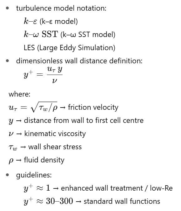
For turbulent flows, select and justify a turbulence model (e.g. k–ε, k–ω SST, LES) and choose a near-wall treatment with an appropriate y⁺ target (≈ 1 for enhanced wall treatment; ≈ 30–300 for standard wall functions). Required y⁺ ranges and wall-treatment options vary by solver and model (e.g. Fluent vs CFX vs OpenFOAM). Always follow your solver’s documentation for the chosen model, and report the achieved wall y⁺ distribution (min/median/max) to show compliance.
When you run the solver, monitor the simulation. look out for warning messages or signs of non-convergence (e.g. residuals plateauing in CFD, or divergence messages in FEA). if the solver fails to converge, stop and adjust settings or refine the mesh or time step. monitor not just residuals but also energy norms, reaction balances, and (for contact problems) contact status; if progress stalls, reduce the time/load step size.
Common issues like rigid body motion (due to insufficient constraints) or singularities (like a point load causing a very high stress in one element) can cause solver problems. Address these by adjusting the model (e.g. add a small stabilising support or a slight fillet to remove a sharp corner) and run again.
Once the simulation completes successfully, the real work is interpreting the results. Do not just copy figures or values blindly – spend time understanding what the results mean. Check the overall behaviour of the system first: deformed shape, flow pattern, temperature distribution, etc. Does it physically make sense?
For example, if you loaded a cantilever beam, the deformation shape should show it bending as expected (with maximum deflection at the free end). If the shape or trend looks odd, there might be a mistake in how you applied the loads or constraints.
Examine key results in detail. For structural problems, locate the points of maximum stress or strain and see if they coincide with expected stress concentrators (such as sharp corners or load application points). Look for patterns like stress concentrations or uniform stress regions, and relate them to the design.
If you find extremely high stresses at a single element, consider if it might be a singularity (an artificial stress spike due to an idealised boundary condition) rather than a real failure hotspot. In fluid simulations, visualise the flow: identify regions of recirculation, high velocity, or pressure drop. Ensure that global balances hold – for instance, verify that the mass flow out equals the mass flow in for a steady flow.
Record the numeric outputs that the assignment requests – for example, the maximum displacement of a structure, or the flow rate at an outlet. Use the software’s post-processing tools to extract these values. It’s good practice to also note where and when they occur (e.g. “Max displacement 5.2 mm at the tip of the beam under load X”).
Throughout the analysis of results, keep referring back to the question: have you obtained the information needed to answer it? The volume of output can be overwhelming (stress maps, contour plots, etc.), so focus on the results that address the original objectives. Summarise intermediate findings as you go, because this will make it easier to write the report and draw conclusions.
Verification and validation of results
Obtaining results is not the end – you must verify that those results are trustworthy. Verification means checking that the simulation solved the equations correctly (e.g. through mesh refinement or ensuring convergence), while validation means confirming that the model’s outputs make sense in reality by comparing with other sources (analytical solutions, experimental data, or established theory). In a student assignment, you may not have new experimental data, but you certainly can compare with hand calculations or textbook results for a simplified scenario.
First, return to the initial hand calculations or theoretical expectations from your planning stage. Do the simulation results fall in the same ballpark? If your hand calc predicted about 100 MPa stress and the FEA shows 500 MPa, that is a red flag – something may be wrong with the setup (or perhaps your assumptions).
Investigate such discrepancies: it could be a mistake in units, a misapplied boundary condition, or a modelling assumption that needs revisiting. On the other hand, if the FEA result is 110 MPa when you predicted ~100 MPa, that gives confidence that the model is capturing the physics correctly.
Where possible, compare the simulation output with known solutions or data. For example, if you are doing a heat transfer simulation, you might compare the result to a simple 1D analytical solution for heat conduction to see if the orders of magnitude align. In structural problems, check if stresses roughly satisfy equilibrium (integrate the stress over an area to see if it equals the applied force, if applicable).
Many software packages have built-in checks (like reaction force sums), which you should use. If your simulation is of a standard problem (say, flow in a pipe), you might validate against theoretical results (e.g. the Hagen–Poiseuille equation for laminar flow). Use these checks as evidence that your model is valid.
Perform sensitivity analyses on critical parameters (Quadco Engineering, n.d.). This could mean slightly changing a boundary condition or material property to see if the outcome changes significantly. If a small change in a parameter causes a huge change in results, your model may be sensitive or unstable, which should be noted and, if possible, mitigated.
A classic example is material properties in a simulation: if you are unsure about a thermal conductivity value, try a higher or lower value to see how much it affects the temperature field. If results barely change, that parameter is not driving the response; if they change a lot, you know the accuracy of that parameter is critical.
A key part of verification is ensuring mesh independence, which we discussed earlier. If you have not already, refine the mesh and re-run the simulation to see if the results converge towards a stable value. You should include this evidence in your report to show that your solution is not an artifact of a coarse mesh.
It is also important to check the energy or mass balance in your simulation, if applicable. For a static structural case, ensure that reaction forces at supports equal the applied loads (equilibrium). For a fluid flow, ensure the mass flow at the outlet equals the mass flow at the inlet. For a thermal steady-state analysis, check that heat input equals heat output at equilibrium. These are fundamental physical laws; if they do not hold, something is wrong with the model.
Throughout verification, maintain a skeptical mindset. If something looks too strange or too extreme, question it. The best engineers are those who can interpret results with a critical eye. As one expert advice puts it, always “keep a critical eye on the results and trust your engineering judgment” rather than blindly trusting the computer output (FEA Academy, n.d.). This might mean going back and adding a missing support, refining the mesh, or even rethinking the approach if validation fails.
Demonstrating this iterative improvement in your assignment – for example, noting “the initial simulation gave an unrealistically high stress, so a refined model or corrected boundary condition was used” – shows a strong engineering approach.
Documenting assumptions and findings
Communicating your work is a significant part of any computational modelling assignment. Document all your assumptions, methods, and findings clearly so that someone else (or the grader) can follow your reasoning (Quadco Engineering, n.d.).
A well-structured report typically includes an introduction (what problem you are solving), a methodology section (how you set up the model), a results section (what you found), and a discussion of those results (what they mean and how reliable they are).
When documenting the methodology, describe the model setup in words and supporting figures. State the geometry that you modelled (with diagrams if possible), and explain any simplifications (e.g. bolt holes were omitted for simplicity).
List the material properties used. Explain the boundary conditions and loads: for instance, you might state that you fixed the left end of the beam in all directions (clamped support) and applied a distributed load of 5 kN/m on the top surface to represent pressure.
By providing this level of detail, you allow readers to understand exactly what was simulated. It also shows you have considered the real-world context.
Include screenshots or plots from the software for key results, but make sure they are legible and annotated. For example, a contour plot of stress is useful – ensure the colour scale and units are shown, and perhaps add an arrow or label for the peak stress location. Graphs of convergence (mesh refinement or iteration residuals) can be included if relevant to demonstrate how you ensured accuracy.
Be explicit about all assumptions in your analysis. If you assumed something like “ignoring wind load” or “assuming adiabatic wall,” state it clearly. Also note any limitations of your model (for example, “this model assumes linear material behaviour and does not account for plastic deformation”). Such honesty about limitations actually strengthens your report, because it shows you understand the model’s scope.
In discussing results, relate them to the original problem. Did the simulation answer the engineering question posed? For instance, you might conclude, “The maximum stress in the beam is 85 MPa, which is below the yield strength of 250 MPa, indicating the design is safe under the given load.”
Also, discuss the significance of the findings: perhaps the simulation suggests a design improvement (e.g. “the highest stress occurs at the sharp corner; rounding this corner could reduce the stress concentration”). If there were discrepancies between simulation and expected values, offer plausible explanations (mesh too coarse, idealisations, etc.).
Throughout the report, maintain a clear and professional style of writing, and use figures and tables to support the text. Number your figures and refer to them (e.g. “Figure 2 shows the pressure distribution along the pipe”). Similarly, if you include any equations or calculations, present them neatly and reference them if they are standard formulas.
Remember to cite any references or sources you used for theory, material data, or validation. In an academic context, proper citation is essential. For example, if you used a formula from a textbook or a material property from a datasheet, cite it. This not only avoids plagiarism but also adds credibility to your work.
By documenting thoroughly and coherently, you demonstrate the reasoning behind your simulation. The grader (or any reader) can see that you didn’t just run software blindly – you understood and justified each step. Good documentation is a habit that will serve you in professional engineering too, where colleagues or clients must be able to review and trust your analysis.
Need engineering assignment help? Our UK‑qualified experts can help with everything from problem sets to dissertations, with fast turnaround if needed. Visit our engineering assignment help page for info.
References and further reading:
- Dimiduk, K., Bhaskaran, R., Zhu, H. and Gao, Y. (2011) ‘Helping Students Approach FEA Simulations like Experts’, Proceedings of the 118th ASEE Annual Conference & Exposition, Vancouver, June 2011. Available at: https://peer.asee.org/helping-students-approach-fea-simulations-like-experts (Accessed: 4 September 2025).
- Quadco Engineering (n.d.) ‘FEA Best Practices’. Quadco Engineering (Online). Available at: https://www.quadco.engineering/en/know-how/fea-best-practices.htm (Accessed: 3 September 2025).
- FEA Academy (n.d.) ‘How to Learn Finite Element Analysis?’ FEA Academy Blog. Available at: https://www.fea-academy.com/ (Accessed: 3 September 2025).
- Fidelis Engineering Associates (n.d.) ‘Why Simulate? – The Benefits of Engineering Simulation’. Fidelis Blog. Available at: https://www.fidelisfea.com/post/why-simulate-the-benefits-of-engineering-simulation (Accessed: 3 September 2025).
Cite This Work
To export a reference to this article please select a referencing stye below:


