Cylinder Taper and Cylinder Out of Round
| ✅ Paper Type: Free Essay | ✅ Subject: Mechanics |
| ✅ Wordcount: 1143 words | ✅ Published: 18 Sep 2017 |
Aditya Patel
Equipment Utilized
An assortment of hand tools, pullers and specialty measuring tools were used during this assignment
Health and Safety Precautions
Safety boots and glasses were mandatory in the shop
Proper lifting techniques, and getting help lifting was very important
Unit Identification
GM 3100 Engine
References
GM 3100 service manual, and our classroom text book were used. Lab notes and internet were used for some of the notes.
Method
1. List all the steps needed to measure cylinder taper and out of round.
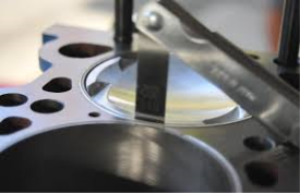
- a bore gauge calibration unit was set up by using fixture and calibration unit
- the bore gauge was placed in this unit and calibrated using the micrometre scale on the unit. To calibrate for specific bore, use the standards. For example, for 4.406 bore, install 4.000+ standard and set the scale to 0.406. Bore gauge is calibrated until the dial shows 0 on it. Or more adjustment should be done.
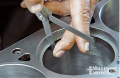
- the bore gauge was then placed inside the cylinder at Top thrust surface and rock the bore gauge front and back until dial goes up and comes back. Note the highest reading, the dial reaches. Do same for bottom thrust surface.
- To measure the cylinder out of round, measure top thrust surface of the cylinder but perpendicular to the first measured.
- Now compare both reading for top thrust surfaces readings. If the difference between the measured reading is more than 0.0005 then the cylinder is out of round or else, it is good.
- To measure the taper, subtract the reading of bottom thrust surface from top thrust surface. If the reading is more than 0.0008 then cylinder is not good.
Cylinder Taper is the difference of the diameter between top of the cylinder bore under the ridge and bottom of the cylinder
Cylinder out of Round is the difference of diameter when measured parallel to crankshaft and then perpendicular to the same at top of the cylinder using bore gauge.
Method – Continued
2. Document 2 methods of measuring piston to cylinder bore clearance.
Feeler Strip Method
- Remove all compression and oil control rings from pistons
- Invert the piston and place it back in the cylinder in upside down position with feeler strip. The feeler strip should not be on the piston pin hole. After piston is placed in the cylinder slowly take the filler gauge out. While taking the filler gauge out, if it feels too hard or loose the try different size of the gauge until you get the perfect size. The perfect size of filler gauge should not feel too tight or smooth while taking it out.
(Measuring clearance using feeler strip)
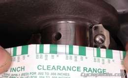
Calculated Method
- Measure the diameter of the piston across the skirt with well calibrated micrometre. Note the reading.
- Now using the bore gauge measure the cylinder diameter under the ridge. Record the reading.
- Now subtract the piston diameter from cylinder diameter. The measurement achieved is the piston to cylinder clearance.
- Note that before taking any reading the micrometre should be well calibrated and the surfaces should be cleaned.
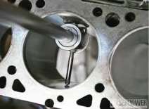
(Bore gauge measuring the cylinder diameter)
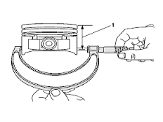
(Measuring piston diameter using Micrometre)
3. Construct a chart listing cylinder, piston ring and crankshaft clearances.
- Located under observations heading
4. Record how to check ring clearances. (side and end)
Side Clearance
- Remove all compression and oil control rings from pistons
- Clean the piston ring groove before measuring.
- For measuring the ring clearance, the ring doesn’t need to be installed in the piston. Gently place the ring in the groove. After placing the ring measure the clearance with the help of feeler gauge between the ring and upper edge of the groove.
- Compare the measured ring clearance with the manufacturers specification. If the measured clearance is more then the manufacturers specification the change the ring.
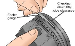
(Measuring Ring Clearance using Feeler Strip)
End Gap
- Remove all compression and oil control rings from pistons
- Place the ring in the same cylinder from which piston come out.
- Using the piston slowly push the ring in the cylinder. Then measure the gap between the two ends of the rings with filler strip.
- The filler strip should not too hard or too smooth to pass between the two ends of the rings.
- Then do same for the second ring and note the measurement. Compare this measurement with the manufacturers specification.
 If the measured end gap is more then the actual specification the change the ring.
(Measuring piston ring end gap using feeler strip)
5. Describe 2 methods of measuring crankshaft bearing clearance.
Plastigauge Method
- remove the main bearing caps from the block and clean the surface of the crankshaft journals with a clean rag.
- Now place a piece of plastigauge according to the width of the journal.
- Install back main bearing caps on their same position as before.
- Check that the bearings are in the correct direction.
- Install the bolts and tighten them with torque wrench at the manufacturers specification.
- Now remove the main bearing caps and check the spread of plastigauge.
- Compare with the marking given on the cover of the plastigauge and note the reading.
- Now compare this reading with the actual specification.
 Before installing main bearings back, carefully wipe the plastigauge marks.
(Measuring the Crankshaft bearing clearance using plasti gauge)
Calculated Method
- Measure the crankshaft journal diameter using a well calibrated micrometre. Measure every journal two times both perpendicular at each other. Note every reading.
- Now put the bearing journals back on. Use torque wrench to tight the bearings with specified torque. Using inside micrometre or bore dial gauge measure the diameter of the bearing. Note the reading.
- To measure bearing clearance, subtract the crankshaft journal diameter measurement from bearing journal diameter.
- The allowable clearance for crankshaft is between 0.0008-0.0025.
6. Explain what causes cylinder taper and cylinder out of round
Cylinder Taper is caused by wear caused by friction and combustion cause the bore to be cone shaped.
Cylinder Out of Round is caused by pressure created by piston rings to the cylinder walls.
Observations
Cylinder
Measurements |
Cyl #1 |
Cyl #2 |
Cyl #3 |
Cyl #4 |
Cyl #5 |
Cyl #6 |
|
(Thrust Surface – Under Ridge) A |
0.0016 |
0.0018 |
0.0018 |
0.0015 |
0.0015 |
0.0014 |
|
(Thrust Surface – Bottom) B |
0.0013 |
0.0014 |
0.0012 |
0.0014 |
0.0011 |
0.0013 |
|
(90 ° – Under Ridge) C |
0.0012 |
0.0015 |
0.0012 |
0.0013 |
0.001 |
0.0011 |
Taper (Subtract “B” from “A”)
Measurements |
Cyl #1 |
Cyl #2 |
Cyl #3 |
Cyl #4 |
Cyl #5 |
Cyl #6 |
|
(Thrust Surface – Under Ridge) A |
0.0016 |
0.0018 |
0.0018 |
0.0015 |
0.0015 |
0.0014 |
|
(Thrust Surface – Bottom) B |
0.0013 |
0.0014 |
0.0012 |
0.0014 |
0.0011 |
0.0013 |
|
Taper |
0.0003 |
0.0004 |
0.0006 |
0.0001 |
0.0004 |
0.0001 |
|
Specification |
0.0008 |
——— |
——— |
——— |
——— |
——— |
Out of Round ( Subtract “C” from “A” )
Measurements |
Cyl #1 |
Cyl #2 |
Cyl #3 |
Cyl #4 |
Cyl #5 |
Cyl #6 |
|
( Thrust Surface – Under Ridge ) A |
0.0016 |
0.0018 |
0.0018 |
0.0015 |
0.0015 |
0.0014 |
|
( 90 ° – Under Ridge ) C |
0.0012 |
0.0015 |
0.0012 |
0.0013 |
0.0010 |
0.0011 |
|
Out of Round |
0.0004 |
0.0003 |
0.0006 |
0.0002 |
0.0005 |
0.0003 |
|
Specification |
0.0005 |
——— |
——— |
——— |
——— |
——— |
Observations – Continued
Piston Ring Clearance
Measurements |
Specs |
#1 |
#2 |
#3 |
#4 |
#5 |
#6 |
|
Ring End Gap: |
|||||||
|
Top Ring |
0.006-0.014 |
0.24 |
0.24 |
0.24 |
0.27 |
0.17 |
0.19 |
|
Second Ring |
0.0197-0.0280 |
0.30 |
0.16 |
0.20 |
0.18 |
0.16 |
0.19 |
|
Ring Groove Clearance: |
|||||||
|
Top Ring |
0.002-0.0033 |
0.002 |
0.0025 |
0.002 |
0.002 |
0.002 |
0.002 |
|
Second Ring |
0.002-0.0035 |
0.002 |
0.002 |
0.0025 |
0.002 |
0.002 |
0.002 |
Bearing Clearance
Checks |
Specs |
#1 |
#2 |
#3 |
#4 |
|
Bearing Bore Dia. (A) |
2.6472 – 2.6502 |
2.649 |
2.652 |
2.648 |
2.650 |
|
Journal Diameter (B) |
2.6473 – 2.6483 |
2.647 |
2.646 |
2.647 |
2.645 |
|
Clearance (A – B) |
0.0008 – 0.0025 |
0.002 |
0.006 |
0.001 |
0.005 |
|
Plastigauge Clearance |
0.0008-0.0025 |
0.0015 |
0.0020 |
0.0010 |
0.0020 |
Conclusions
Upon completing the measurements and visual inspections, I would recommend that due to the excessive wear and out of round cylinder, the cylinder should be bored. While measuring the piston ring clearance we noticed that the piton rings were replaced and were both of same size on one piston.
Cite This Work
To export a reference to this article please select a referencing stye below:
Related Services
View all


DMCA / Removal Request
If you are the original writer of this essay and no longer wish to have your work published on UKEssays.com then please click the following link to email our support team:
Request essay removal