Experimental Study and Performance Test of Composite Internal Fins
| ✅ Paper Type: Free Essay | ✅ Subject: Environment |
| ✅ Wordcount: 1588 words | ✅ Published: 23 Sep 2019 |
Experimental Study and Performance Test of Composite Internal Fins
Abstract
Heat transfer performance for both brass and composite (Al+SiC) finned of brass pipe has been investigated experimentally. The composite finned tube was designed, fabricated and installed and was heated electrically. The same was done for a brass finned tube in order to make comparison. Heat transfer coefficient for composite finned tube is about 1.09 to 1.11 times higher than that of brass finned tube. Higher thermal conductivity of composite material is responsible for this heat transfer enhancement. The composite finned tube in this study produces significant heat transfer enhancement at the same Reynolds number than that of brass finned tube.
Keywords: Heat transfer, composite fin, thermal conductivity.
1. Introduction
Internal fins are used in phase change material storages (PCM). PCM are used to balance the temporary temperature alteration and to store energy in several practical fields like automobile industries. The rate of heat transfer from fluid flowing through the micro channels can be greatly enhanced by use of internal fins. T.Kanthimathi [1] focused on the study of the radial composite fins to increase the heat transfer rate in many applications. Y. Pratapa Reddy[2] made to fabricate circular pin fin made of different metals, Aluminium ,Copper, combination of Aluminium and Copper and combination of Brass and Copper as composite bars and analyzed their performance in terms of fin efficiency , heat transfer rate and temperature distribution along the fin. Jiang[3] measured the performance of conventional silica gel coated heat exchanger (SGCHE), a novel composite silica gel coated heat exchanger (CCHE) was proposed and fabricated. Wu Xuehong[4] investigated the performance of air-side heat transfer and fluid flow by numerical simulation for Reynolds number ranging from Re = 304 to 2130. The objective of the research is to study the effect of composite internal longitudinal fins in a circular tube on heat transfer characteristics in the entrance region as well as in the fully developed region.
2. DESIGN & CONSTRUCTION
Sand casting was used in this experiment to manufacture brass pipe. Composites were made from 98% pure aluminum. In this experiment pure SiC was used in 10 % weight fraction with aluminum. Mg (1 wt %) was added to improve the wettability and incorporation fraction of ceramic particles. Micro-sized SiC particles were used as reinforcement of pure aluminum to fabricate as-cast aluminum matrix composite, and Mg (1 wt%) was added to improve the wettability and incorporation fraction of ceramic particles.
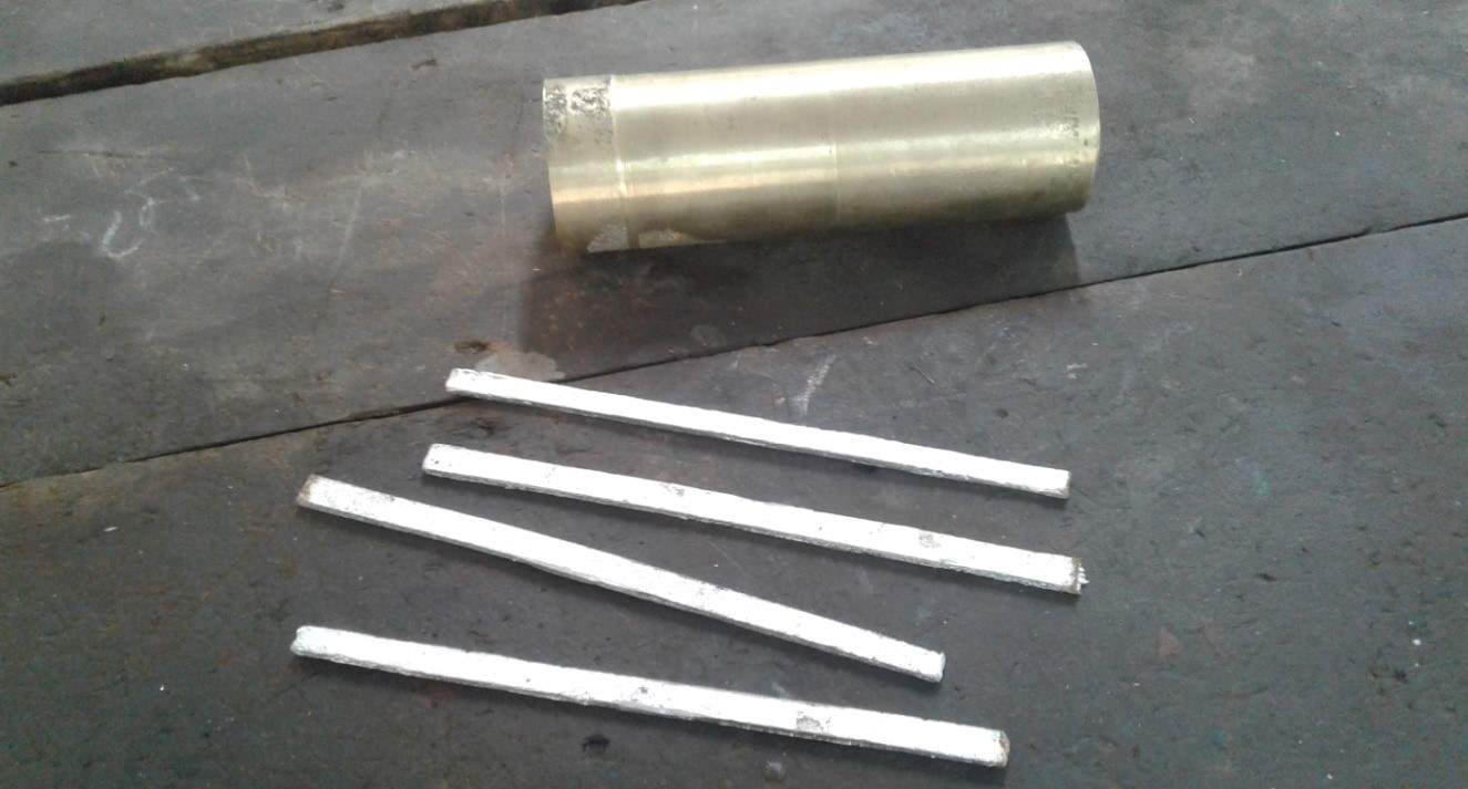
Figure 1 Composite (Al+SiC) rectangular fins with brass pipe
Adhesive was used to join the composite fins with the brass pipe.
3. EXPERIMENTAL SETUP
An experimental set up was designed, fabricated and installed to study the heat transfer performance of circular tube having internal longitudinal fins. Air was used as the working fluid.
Dimensions of pipe and fins:
Length of the cylindrical pipe, L= 25.5 cm = .255 m
Inner diameter of the tube, Di = 8.38 cm = .0838 m
Outer diameter of the tube, Do = 8.89cm = .0889 m
Height of fin, H = .013 m
Thickness of fin, W = .003 m
Total number of fin, N = 4
Procedure of Experiment:
The fan was first switched and allowed it to run for a few minutes so that the transient characteristic died out. Then electrical heating circuit was switched on. The readings for the velocity were taken by hot wire anemometer along the diameter of the pipe. First the variation in wall thermocouples was observed until constant values were attained; then the outlet air temperature was monitored.
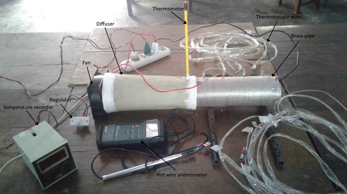
Figure 3.1 Experimental setup of composite (Al+SiC) finned tube
After one run of the experiment at a particular Reynolds number, the Reynolds number was changed with the help of the flow control regulator keeping electrical power input constant. All the thermocouples readings were taken at each axial direction for each run of the experiment.
Same experimental procedure was applied for both brass and composite (Al+SiC) finned tube.
4. EQUATIONS
Reynolds Number:
Re = 
Mean velocity of test section, V =  , [Properties of fluid are calculated at its bulk temperature]
Heal transfer calculation:
Total heat taken by air, Q = MCp(To – Ti)
Heat taken per unit area, Q΄ = 
The local bulk temperature of the fluid can be calculated according to the following way-
Q΄ =  =
= 
 =
= 
Now, bulk temperature, Tbx = Ti +  ) x = Ti +
Local convective heat transfer coefficient is given by hx = 
Local Nusselt number is, Nux = 
List of Symbols
Axf Cross sectional area of finned tube (m)
Cp Specific heat of air (kJ/kgC)
M Mass flow rate (kg/s)
Q Rate of heat transfer (W)
T Temperature (oC)
x Axial distance (m)
ρ Density or air (kg/m3)
Tbx Bulk temperature of fluid (oC)
Twx Wall temperature of brass pipe (oC)
hx Local heat transfer coefficient (W/ m2oC)
Nux Local Nusselt number (-)
5. Experimental result
Table 4.1 Data of Heat Transfer of Brass Finned Tube
|
X(m) |
Tbx (oC) |
Twx (oC) |
hx (W/m2 oC) |
Nux |
|
0.03 |
25.98 |
110 |
24.97 |
55.38 |
|
0.09 |
27.94 |
121 |
23.86 |
52.92 |
|
0.16 |
29.89 |
133 |
23.37 |
51.83 |
|
0.23 |
31.85 |
142 |
23.16 |
51.37 |
Table 4.2 Data of Heat Transfer of Composite (Al+SiC) Finned Tube
|
X(m) |
Tbx (oC) |
Twx (oC) |
hx (W/m2 oC) |
Nux |
|
0.03 |
26.22 |
105 |
43 |
87.75 |
|
0.09 |
28.67 |
122 |
51 |
75.17 |
|
0.16 |
31.12 |
129 |
62 |
72.71 |
|
0.23 |
33.57 |
132 |
68 |
71.54 |
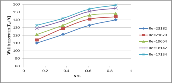
Figure 4.1 Wall temperature distribution along the length of the brass finned tube
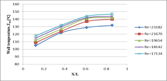
Figure 4.2 Wall temperature distribution along the length of the composite (Al+SiC)
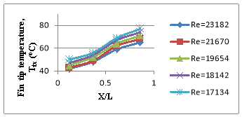
Figure 4.3 Fin tip temperature along the length of the brass finned tube
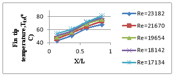
Figure 4.4 Fin tip temperature along the length of the composite (Al+SiC) finned tube
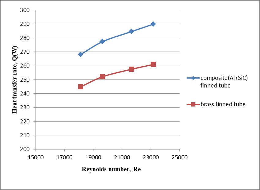
Figure 4.5 Variation of heat transfer with Reynolds Number

Figure 4.6 Variation of Nusselt number with Reynolds Number
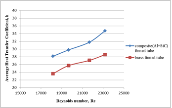
Figure 4.7 Variation of average heat transfer coefficient with Reynolds Number
6. Discussion
Figure (4.1, 4.2) shows the wall temperature distribution along the length of the finned tube for different Reynolds number based on inside diameter At higher Reynolds number the-wall temperature is low because more heat is taken away by the air. Nusselt number is large in the entrance region due to the development of thermal boundary layer with the entrance section as the leading edge. It decreases with increasing the axial distance approaching the fully developed values and then it increases with the axial distance which is very unusual occurrence and needs further investigation. Figure 4.5 shows that at higher Reynolds number the heat transfer rate increases.
7. Conclusion
In this experiment heat transfer performance was studied. Steady state fluid flow and heat transfer performance of circular tube with internal longitudinal brass finned tube and composite finned tube were studied experimentally. Results indicate that the heat transfer performance for composite finned tube is higher than that for a brass tube. For both tubes local heat transfer coefficient is high in the entrance region as at this portion the cold air start to mix up with the hot tube and it decreases with increasing the axial distance approaching the fully developed value.
Heat transfer for the composite finned tube is 1.07 to 1.09 times higher than that of brass finned tube for comparable Reynolds number. The results thus show that composite finned tube results in heat transfer enhancement.
8. References
[1] T.Kanthimathi, Naga Sai Ram. G, Heat transfer through annular composite fin, Journal of
mechanical engineering and technology, 2016, vol. 4, pg. 01-10
[2] Y. Pratapa Reddy, B. Jithendra Kumar, G. Raju, Fabrication and Thermal Analys
Composite Pin-Fin, International journal of core Engineering and management, 2015,
ISSN: 2348-9510, volume 2, issue 5, pp 77-89
[3] Y. Jiang, T.S. Ge, R.Z. Wang, L.M. Hu, Experimental investigation and analysis of
composite silica-gel coated fin-tube heat exchangers, International journal of
refrigeration, 2014
[4] Wu Xuehong , Zhang Wenhui, Gou Qiuping, Numerical simulation of heat transfer
and fluid flow characteristics of composite fin, International journal of heat and mass
transfer, 2014, vol. 75, pg. 414–424
Cite This Work
To export a reference to this article please select a referencing stye below:
Related Services
View allDMCA / Removal Request
If you are the original writer of this essay and no longer wish to have your work published on UKEssays.com then please click the following link to email our support team:
Request essay removal


