Automated Detection of Fall among the Elderly Using Accelerometer Analysis
| ✅ Paper Type: Free Essay | ✅ Subject: Technology |
| ✅ Wordcount: 1285 words | ✅ Published: 23 Sep 2019 |
Automated Detection of fall among the elderly using accelerometer analysis
- Introduction
- Project Description
- Project Plan
- Progress to Date
- Discussion and Conclusion
- References
1. Introduction
The aim of this report is to provide progress details of the project, goals and plans for the year to complete the project. To achieve this aim, some tools would be used in this report such as block diagrams, circuit diagrams flowcharts and project plan for this project as agreed with the supervisor.
2. Project Description.
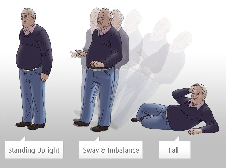
The aim of the project is to develop a system to detect fall among the elderly using an accelerometer, to be able to send a short message service (SMS) message over the Short Message Service Centre (SMSC) when the fall occurs and to design a fall detector system based on algorithm to detect the fall
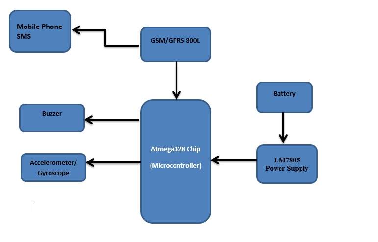
In order to achieve this system, the following components will be required such as an Arduino Uno ATmega 328p, a mobile phone SMS, accelerometer and a buzzer to achieve the desired result. The language that will be used in the project will be programmed using C++.
2.1 Block diagram
2.2 Flowchart for Algorithm
The following flowchart in Figure 3 below shows the flowchart for the algorithm to be used for the project:


Start
Initialize System
Monitoring
x,y,z Accelerometer
x,y,z gryrometer measuring

Fall
 NO
NO
YES
Send SMS
Sound buzzer
End
Figure 2.2 Flowchart of the project
A program flow chart as displayed in Figure 2.2 as shown explains the steps involved in the completion of the project. The program will start with the initialization of the system. Then, it is followed by monitoring the accelerometer and gyroscope. If an individual falls, a SMS will be sent to the individual monitoring the fall as a sound buzz.
2.3 ARDUINO UNO MICROCONTROLLER
The Arduino Uno is a microcontroller board based on the ATmega328p. The Arduino Uno is widely acceptable because of its easy online availability online source code coupled with its programming capability and. It is made up 14 digital input/output pins (6 PWM (Pulse width modulation) outputs), 6 analog inputs, ceramic resonator, a USB (universal serial bus) connection, a power jack, an ICSP (in-circuit serial programming) header, and a reset button. It functions on a low current of between 40 to 50 mA and a voltage of between 0 to 5 v. it can be powered by either using a USB connection or an external power jack. Due to its size in memory of 32KB it can programmable using an Arduino IDE (Integrated development environment).
2.4 SIM 800L Mini GSM/GPRS module
The SIM 800L is a mini cellular model that is used for transmitting and receiving data through a cellular network. It can be used to receive and send messages and calls. Due to its low cost, small size and quad frequency band it makes it the most efficient for transmitting and receiving at a long range. After its setup and booting when the power comes on it searches automatically and connects to the network while the LED (Light emitting diode) on its board shows the connection state.
2.5 MPU 6050 Gyroscope and Accelerometer
The MPU 6050 is a device that is made up of a 3- axis accelerometer, 3 axis gyroscope and a digital thermometer. it is used for motion sensing. it has a special feature that is inbuilt which is the Digital motion processor unit (DMP) which is capable of processing complex 9 axis motion fusion data. it has an input voltage which ranges from 3 to 5 volts. It interfaced which I2C (Inter-Integrated Circuit) communications and supports it up to 400kHz.
3. Project Plan
Time Management: it is the period taken to complete some weekly task which may vary. Although tasks may be delayed in the process which is natural in a project, sometimes when this occurs it is best to complete other tasks before returning to the incomplete task to complete it.
Deadline
|
Task
|
08-10-2018
|
Preliminary Report Submitted
|
1-11-2018
|
Research on the topic of automated fall detection
|
15-11-2018
|
Selection and building of a suitable wearable accelerometer-based data acquisition system with the capability to communicate with external network.
|
26-11-2018
|
Use of the developed hardware system to capture a data set of simulated falls and non-fall related activity.
|
27-11-2018
|
Required components purchase
|
09-01-2019
|
Progress report and presentation submission
|
28-01-2019
|
Deployment and evaluation of an automated fall detection algorithm and evaluation of
|
22-02-2019
|
Deployment of the developed algorithm on the developed hardware for real time demonstration of system operation. Final test results and verification with simulation results
|
28-02-2019
|
Final test results and verification
|
08-03-2019
|
Conclusions and Discussions
|
12-03-2019
|
Poster presentation with project coordinator and presentation of first draft of report.
|
18-03-2019
|
Poster presentation
|
25-03-2019
|
Presentation of final hard bind report to project coordinator
|
- Progress till date
From the project description and the plan to complete the project, this section explains and displays the progress that has been made to accomplish the set earlier goals that should have been completed at this time.
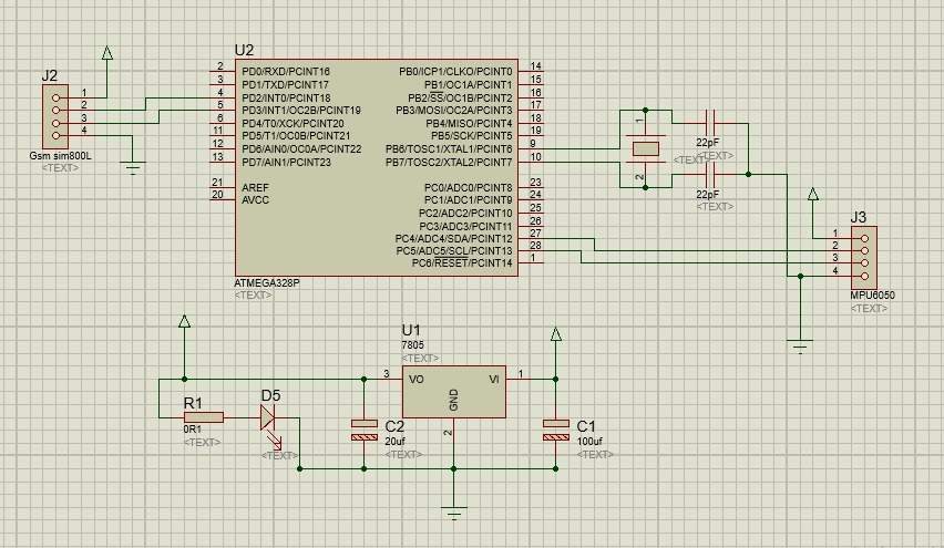
The above fig 5 .1 is circuit diagram for the project
Accelerometers measure the acceleration of a moving or vibrating body. But when accelerometer is in a fixed position,
only the gravity pulling it down is sensed. It detects linear acceleration along three axis namely x, y and z. Sampling each
each axes data would provide an accurate idea of the orientation of the object. To ensure accuracy, calibration of the accelerometer
must be done. While doing this the accelerometer must be put in a fixed position as shown in figure
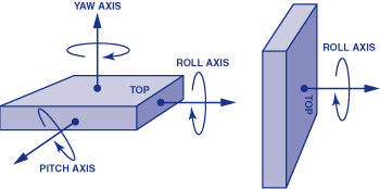
Both X and Y axis readings must be 0 since they are parallel to the ground while the Z axis reading must be the
maximum. Adjusting the correcting factor helps obtaining this. In terms of g’s (gravity values), the XYZ axis values would
be in the form (0g, 0g, 1g)
Dividing corrected analog values by the maximum help converts voltage values into g’ values.
The following equation is used to obtain net acceleration
{
Serial.println();
Serial.print(” * Sleep Mode: “);
Serial.println(mpu.getSleepEnabled() ? “Enabled” : “Disabled”);
Serial.print(” * Motion Interrupt: “);
Serial.println(mpu.getIntMotionEnabled() ? “Enabled” : “Disabled”);
Serial.print(” * Zero Motion Interrupt: “);
Serial.println(mpu.getIntZeroMotionEnabled() ? “Enabled” : “Disabled”);
Serial.print(” * Free Fall Interrupt: “);
Serial.println(mpu.getIntFreeFallEnabled() ? “Enabled” : “Disabled”);
Serial.print(” * Free Fal Threshold: “);
Serial.println(mpu.getFreeFallDetectionThreshold());
Serial.print(” * Free FallDuration: “);
Serial.println(mpu.getFreeFallDetectionDuration());
Serial.print(” * Clock Source: “);
switch(mpu.getClockSource())
{
case MPU6050_CLOCK_KEEP_RESET: Serial.println(“Stops the clock and keeps the timing generator in reset”); break;
case MPU6050_CLOCK_EXTERNAL_19MHZ: Serial.println(“PLL with external 19.2MHz reference”); break;
case MPU6050_CLOCK_EXTERNAL_32KHZ: Serial.println(“PLL with external 32.768kHz reference”); break;
case MPU6050_CLOCK_PLL_ZGYRO: Serial.println(“PLL with Z axis gyroscope reference”); break;
case MPU6050_CLOCK_PLL_YGYRO: Serial.println(“PLL with Y axis gyroscope reference”); break;
case MPU6050_CLOCK_PLL_XGYRO: Serial.println(“PLL with X axis gyroscope reference”); break;
case MPU6050_CLOCK_INTERNAL_8MHZ: Serial.println(“Internal 8MHz oscillator”); break;
}
Serial.print(” * Accelerometer: “);
switch(mpu.getRange())
{
case MPU6050_RANGE_16G: Serial.println(“+/- 16 g”); break;
case MPU6050_RANGE_8G: Serial.println(“+/- 8 g”); break;
case MPU6050_RANGE_4G: Serial.println(“+/- 4 g”); break;
case MPU6050_RANGE_2G: Serial.println(“+/- 2 g”); break;
}
Serial.print(” * Accelerometer offsets: “);
Serial.print(mpu.getAccelOffsetX());
Serial.print(” / “);
Serial.print(mpu.getAccelOffsetY());
Serial.print(” / “);
Serial.println(mpu.getAccelOffsetZ());
Serial.print(” * Accelerometer power delay: “);
switch(mpu.getAccelPowerOnDelay())
{
case MPU6050_DELAY_3MS: Serial.println(“3ms”); break;
case MPU6050_DELAY_2MS: Serial.println(“2ms”); break;
case MPU6050_DELAY_1MS: Serial.println(“1ms”); break;
case MPU6050_NO_DELAY: Serial.println(“0ms”); break;
}
Serial.println();
}
///////////////////////////////////////////////////////////////////////////////////////////////////////////
void loop()
{
Vector rawAccel = mpu.readRawAccel();
Activites act = mpu.readActivites();
Serial.print(act.isFreeFall); //
Serial.print(“
”);
if (freefallDetected)
{
ledState = !ledState;
digitalWrite(13, ledState);
freefallBlinkCount++; // count the number of time the threshhold has been attained
if (freefallBlinkCount == 5) // at a minimum of 5 counts the fall should be detected
{
freefallDetected = false;
ledState = false;
digitalWrite(13, ledState);
Serial.println(“Fall!!!”); // print out fall
/////////////////////////////////////////////////////////////Gsm function//////////////////////////////////////////
//////////////////////////////////////////////////////////////////////////////////////////////////////////////////
}
}
delay(100);
http://www.ece.montana.edu/seniordesign/archive/SP14/UnderwaterNavigation/Euler%20Angles.html
Cite This Work
To export a reference to this article please select a referencing stye below:
Related Services
View all


DMCA / Removal Request
If you are the original writer of this essay and no longer wish to have your work published on UKEssays.com then please click the following link to email our support team:
Request essay removal