Fill Factor Analysis of Organic Solar Cell
| ✅ Paper Type: Free Essay | ✅ Subject: Physics |
| ✅ Wordcount: 1448 words | ✅ Published: 01 Feb 2018 |
Rashmi Swami, Rajesh Awasthi, Sanjay Tiwari
Abstract
Solar cell is a device used to convert light into electricity. It can be made by organic and inorganic materials. Its most important parameters are open circuit voltage, short circuit current, fill factor and conversion efficiency. This paper is based on the analysis of factors that affect the fill factor of organic solar cell using MATLAB. Fill factor is calculated using conventional organic solar cell model without series and shunt resistances and constant light generated current for two different cases –first using Exponential dark characteristic and second using Polynomial dark characteristic. We get for exponential V-I relationship increase in ideality factor n, will reduce the fill factor and for polynomial V-I relationship increase in m will increase fill factor. A large dependence of light generated current Iph on increasing applied voltage would cause a significant drop in fill factor. Increase or decrease in an additional factor  would accordingly change fill factor. Dark current can be varied in two ways, one by varying mobility and other by varying injection barrier heights. In both the cases fill factor increases proportionately with .
Keywords – Organic solar cell, fill factor, ideality factor, open circuit voltage, HTL, ETL.
- Introduction
Bilayer organic solar cell as shown in fig. 1(a) is a device in which thin layer of organic material (donor and acceptor) is used between electrodes to convert light into electricity. This work is completely based on bilayer structure of organic solar cell as shown in fig.1(a) in which poly(9,9′-dioctylfluorene-co-bis-N,N’-(4-butylphenyl)-bis-N,N’-phenyl-1,4phenylenediamine) (PFB) is organic donor/HTL and poly(9,9′-dioctylfluorene-co-benzothiadiazole) ( F8BT) is organic acceptor/ETL. Fig. 1(b) shows simplest conventional organic solar cell model without series and shunt resistances. Open circuit voltage, short circuit current, fill factor and efficiency are four important parameters of OSC.
FF = Vmax Imax / VOC ISC
When Vm= VOC and Im= ISC then (FF)max=1.
For a good photo-voltaic device, all three factors FF, VOC, ISC should be large so that it can deliver large output power for the same incidental optical power.
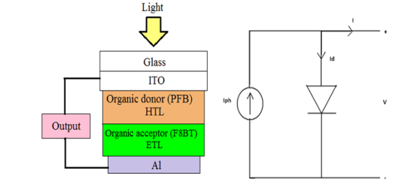
- (b)
Fig. 1 : (a) Bilayer organic solar cell structure. (b) Conventional organic solar cell model without series and shunt resistances.
- Simulation Model and Analysis of Fill Factor
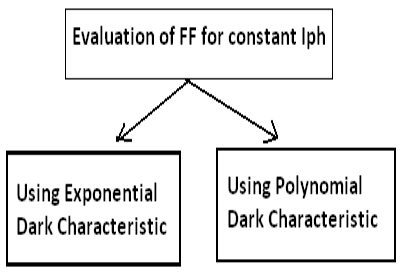
Two cases have been studied, one where dark characteristic is exponential like p-n junction and other where dark characteristics is polynomial like in space charge limited devices.
1.2.1Exponential Current Voltage Relationship –
In this model, dark characteristic is assumed to follow exponential current voltage relationship and Iph is assumed to be constant.
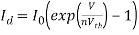 (1)
(1)
where n is ideality factor and Vth is thermal voltage, Iph is light generated current, Id is dark current and I is net output current.
Total output measured current can be written as a function of photo-generated current and dark current.
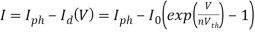 (2)
(2)
Output power of organic solar cell when it is operating at voltage V and giving current I-
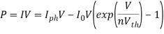
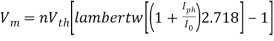
If maximum power is obtained at voltage Vm,
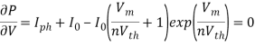
 , here assuming
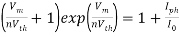
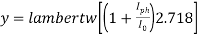
 (3)
(3)
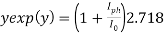
Here y exp(y) is Lambert’s W function
 (4)
(4)
and 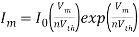 (5)
(5)
At VOC net output current will be zero. At this condition eq. (2) will give
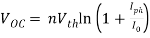 (6)
(6)
1.2.2 Polynomial Current-Voltage Relationship–
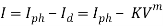
In this case it is assumed that dark current depends on the applied voltage in the following manner-
 (7)
(7)
Where K is constant and  .
.
 (8)
(8)
If photovoltaic is operated at voltage V and output current is I, output power will be-
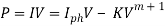
To calculate fill factor, one needs to find out the maximum power which photo-voltaic cell can supply. If maximum power is delivered at voltage Vm
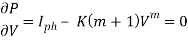
This will give, 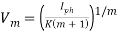 (9)
(9)
and  (10)
(10)
At VOC net output current will be zero. At this condition eq. (8) will give
 (11)
(11)
and 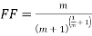 (12)
(12)
1.2.3 Effect of Dark Current on Fill Factor – Simulation using 1D drift-diffusion electrical modeling of bilayer OSC in MATLAB is done. We obtained that the dependence of light generated current on the applied voltage means that fill factor would depend on it as well besides shape of dark characteristics. An estimate of variation of light current can be obtained by taking ratio of its value at short circuit and open circuit condition –
At 0 volt, 
At VOC,  i.e.
i.e. 
The ratio  is a measure of how drop in Iph with the voltage. This ratio can be written as –

Thus shows an additional factor that would affect fill factor. As this factor increases or decreases, the fill factor should accordingly change too.
- Results and Conclusions
- Eq. (3) suggests that as ideality factor n is changed, keeping reverse saturation current I0 and photo-generated current Iph constant, Vm changes in such a manner that (Vm/n) remains constant. So Im will also be constant as it is a function of (Vm/n). From eq. (6) open circuit voltage is also changes with ideality factor n such that (VOC/n) remains constant. It follows from the above reasoning that (Im/ISC) and (Vm/VOC) will be unchanged if n will vary keeping the reverse saturation current constant. Hence as ideality factor n varies keeping the reverse saturation current I0 constant, fill factor of the device will remain unchanged. Though if open circuit voltage (VOC) assumed to be constant by varying reverse saturation current I0 as ideality factor n changes, fill factor will change accordingly.
Assuming Iph to be 1 mA-cm-2, I0 to be  mA-cm-2 and ideality factor n to be 1, open circuit voltage and fill factor come out to be 1.25 volts and 0.9 respectively. Taking Iph and VOC constant, the variation of fill factor with ideality factor n is shown in fig. 2. We get that increase in the value of ideality factor n, will reduce the value of fill factor
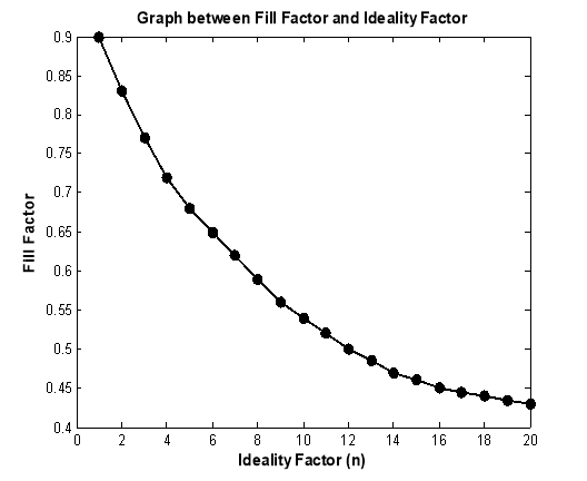
Fig. 2 : Variation of fill factor with ideality constant n. open circuit voltage and light generated current are taken to be constant as 1.25 V and 1 mA-cm-2 respectively.
- Eq. (12) shows that fill factor is a function of m. Variation of fill factor with m is shown in fig. 3. For m = 1, FF = 0.25. As m increases fill factor also increases and approaches to 1. However, FF will become only 1 when m is infinity. In this case also, m is a measure of the sharpness of the characteristic curve. As m increases, I-V curve becomes increasingly sharper resulting in a high fill factor. For polynomial dark characteristic with constant light generated current we get that increase in m will increase fill factor which approaches to 1
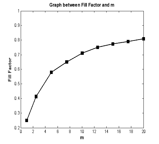
Fig. 3 : Variation of fill factor with m. fill factor approaches to 1 as m becomes larger and larger.
- Simulation results revealed in fig. 4 show that light generated current Iph is a function of applied voltage, means FF would depend on it as well besides shape of dark characteristic. A large dependence of Iph on increasing applied voltage would cause a significant drop in FF. Increase or decrease in an additional factor would accordingly change fill factor. Dark current can be varied in two ways, one by varying mobility and other by varying injection barrier heights. In both the cases fill factor increases proportionately with as shown in fig. 5 and fig. 6.
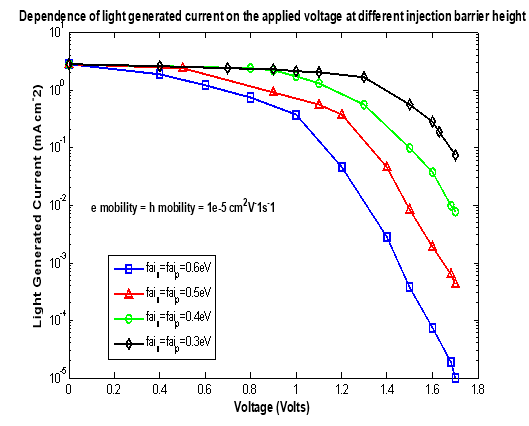
Fig. 4 : Dependence of light generated current on the applied voltage.  and
and  are the hole and electron mobilities respectively.
  and
and  are the injection barriers at anode and cathode respectively.
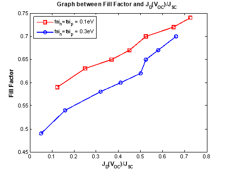
Fig. 5 : Variation of fill factor with for 0.1eV and 0.3eV injection barrier heights. Different points have been obtained by changing mobility.
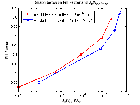
Fig. 6 : Variation of fill factor with for carrier mobilities  and
and  . Different points have been obtained by changing injection barrier height.
References
- J. A. Barker, C. M. Ramsdale, and N. C. Greenham, “Modeling the current-voltage characteristics of bilayer polymer photovoltaic devices”, Physical Review B 67, (2003), 075205.
- D. P. Grubera, G. Meinhardtb and W. Papousekc, “Modelling the light absorption in organic photovoltaic devices”, Solar Energy Materials and Solar Cells, 87, (2005), 215-223.
- J. Wagner, T. Fritz, and H. Bottcher, “Computer modelling of organic thin film solar cells exciton model of photocurrent generation”, Physica Status Solidi A, 136, (1993), 423.
- Y. Roichman and N. Tessler, “ Generalized Einstein relation for disordered semiconductors implications for device performance”, Appl. Phys. Lett., 80, (2002), 1948.
- J. C. Scott and G. G. Malliaras, “Charge injection and recombination at the metal-organic interface”, Chem. Phys. Lett., 299, (1999), 115.
- S. E. Shaheen, C. J. Brabec, N. S. Sariciftci, F. Padinger, T. Fromherz, and J. C. Hummelen,” 2.5 % efficient organic plastic solar cells”, Appl. Phys. Lett., 78, (2001), 841-843
- B. K. Crone, P. S. Davids, I. H. Cambell and D. L. Smith, “Device model investigation of bilayer organic light emitting doide”, J. Appl. Phys., 84, (2000), 1974.
- P. W. M. Blom, M. J. M. de Jong and S. Breedijk, “Temperature dependent electron hole recombination in polymer light emitting diodes”, Appl. Phys. Lett., 71, (1997), 930.
- C. M. Ramsdale, J. A. Barker, A. C. Arias, J. D. MacKenzie, R. H. Friend and N. C. Greenham, “The origin of open circuit voltage in polyfluorene-based photovoltaic device”, J. Appl. Phys, 92, (2002),4266.
- B. Mazhari, “An improved solar cell circuit model for organic solar cells”, Solar Energy Materials & Solar Cells, 90, (2002), 1021.
Cite This Work
To export a reference to this article please select a referencing stye below:
Related Services
View all


DMCA / Removal Request
If you are the original writer of this essay and no longer wish to have your work published on UKEssays.com then please click the following link to email our support team:
Request essay removal