Environmental Footprint of Wind Energy
| ✅ Paper Type: Free Essay | ✅ Subject: Environmental Sciences |
| ✅ Wordcount: 2448 words | ✅ Published: 23 Sep 2019 |
- Goal and scope (ISO 14040)
The present LCA is composed on a comparative base in the field of wind energy, assessing an onshore 2MW and an offshore 5MW wind turbine. The aim of the study is to give a clear insight towards the actual environmental footprint of wind energy and to provide possible ways of sustainable development and advance in the field of wind turbines as the core equipment for alternative energy production. The LCA will assess the entire life period of wind turbines onshore (2MW) vs offshore (5MW) in strategic planning, by critically approaching them as ‘ecofriendly’ choice and the final goal of the study is to be lead to a decision concerning the increase or decrease of production, always in terms of sustainable energy production.
The study is communicated to wind energy trading management in EU and to all concerned in the energetic issue researchers or traders, however the study may serve as a tool to apply to any other location with adaption of appropriate data. Since each wind farm is consisted by different number of units and is affected by various other factors, the current LCA will be based on the functional unit of 1kWh of output energy, for blades manufactured using glass fiber onshore and offshore wind turbines. The lifetime horizon of this equipment accounts for 25 years of safe operation. After this time interval, it is necessary to assess solutions for disposal, reuse, or recycling strategy to define a sustainable end of life strategic planning. The system boundaries of the study are raw materials extraction/production, manufacturing of the turbine, assembly, transportation to use location, operation, maintenance, dismantling and finally disposal or recycling. This is a cradle to grave assessment.
- Inventory Analysis (ISO 14041)
A wind turbine is based on the energy gained through rotation of the blades by the wind, where mechanical energy is transformed into electrical. A wind turbine, onshore or offshore, consists mainly of blades, rotor, gear box, generator, nacelle and tower. Other elements serving the functioning and electrical equipment of the turbines are not a matter of study of the current LCA. A small description of the mechanism follows in Table 1.
Table 1: Main components and respective function ((2))
| Part | Function |
| Blades | Airfoil aiming to capture energy from fast and strong wind, being lightweight, durable and corrosion resistant |
| Rotor | Uses contact area of wind and is rotating around the generator with the help of the low speed shaft |
| Gear box | Aims to magnify the energy output of the rotor, located between the generator and the rotor |
| Generator | Produces electricity from the rotation of the rotor |
| Nacelle | Aims the sealing and protection of the generator against other elements and harsh environment |
| Tower / Foundation | Carries the nacelle and the rotor, foundation of structure |
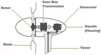
Figure 1: Schematic of components ()
For the purpose of studying accurately the environmental impact of wind turbines, it is important to identify the material used for the production of each element of wind turbines, the production process, as well as, its respective mass. For the mass calculation of the onshore as well as, for the offshore wind turbine, contribution of material and mass from foundation pile and basement is taken into consideration, as it is one of the most important parameters influencing mass and energy consumed. The following accumulation is only a measure of the wind turbines and not for the structures supporting them on the site. From technical point of view, onshore and offshore turbines, of 2MW and 5 MW respectively, are considered to be manufactured by the same components, with equal materials and processing. Their actual difference lies on the coating and tower structure and foundation which is implying additional mass at the offshore scenario.
Table 2: Onshore wind turbine materials, processing and mass accumulation ((2)) ((1))
| Part | Main Material | Production Process | Mass (kg) |
| Tower | Low Carbon Steel | Forging, Rolling | 164.000 |
| Nacelle gears | Stainless Steel | Forging, Rolling | 19.000 |
| Nacelle main shaft | Cast Iron | Casting | 12.000 |
| Nacelle cover | GFRP | Composite forming | 4.000 |
| Nacelle transformer core | Gray Cast Iron | Forging, Rolling | 6.000 |
| Nacelle generator core | Gray Cast Iron | Forging, Rolling | 9.000 |
| Nacelle conductors | Copper | Forging, Rolling | 3.000 |
| Nacelle conductors | Aluminium | Forging, Rolling | 1.770 |
| Nacelle forged components | Stainless steel | Forging, Rolling | 3.000 |
| Nacelle cast components | Cast Iron | casting | 4.000 |
| Rotor blades and spinner | GFRP | Composite forming | 248.000 |
| Rotor spinner | Cast Iron | Casting | 2.200 |
| Foundation | Steel | Forging, Rolling | 27.000 |
| Foundation pile | Concrete | Construction | 1.100 |
| Other components | PE, epoxy, etc. | Polymer extruxion | 1.380 |
| Σ= 505.3E + 003 |
Table 3: Offshore wind turbine materials, processing and mass accumulation ((3))
| Part | Main Material | Production Process | Mass (kg) |
| Tower | Low Carbon Steel | Forging, Rolling | 164.000 |
| Nacelle gears | Stainless Steel | Forging, Rolling | 19.000 |
| Nacelle main shaft | Cast Iron | Casting | 12.000 |
| Nacelle cover | GFRP | Composite forming | 4.000 |
| Nacelle transformer core | Gray Cast Iron | Forging, Rolling | 6.000 |
| Nacelle generator core | Gray Cast Iron | Forging, Rolling | 9.000 |
| Nacelle conductors | Copper | Forging, Rolling | 3.000 |
| Nacelle conductors | Aluminium | Forging, Rolling | 1.770 |
| Nacelle forged components | Stainless steel | Forging, Rolling | 3.000 |
| Nacelle cast components | Cast Iron | casting | 4.000 |
| Rotor blades and spinner | GFRP | Composite forming | 248.000 |
| Rotor spinner | Cast Iron | Casting | 2.200 |
| Tower structure | Reinforcing Steel | Construction | 202.900 |
| Foundation | Steel | Forging, Rolling | 1.150.000 |
| Other components | PE, epoxy, etc. | Polymer extruxion | 1.380 |
| Other components | Lead, coating | Forming | 1.661 |
| Σ= 1.859E + 006 |
At the present LCA the system’s boundary conditions assumed are analytically the following: material extraction or production, turbine and components manufacturing, transportation to work site, installation, operation and maintenance during safe life operation, disassembly at the end of life and finally end of life or partial disposal and recycling to the first stages. The analysis is a commutative work, intending to identify the final sum of energy and material requirements, as well as CO2 emissions, during the life span of 25 years.
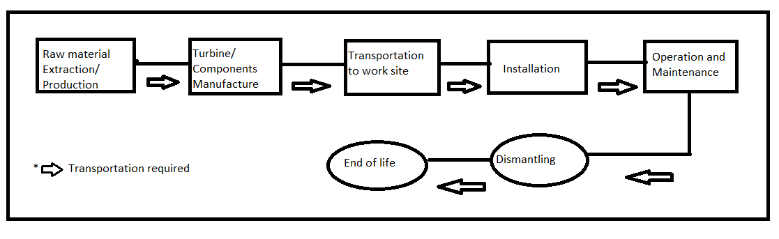
Figure 2: System Boundaries Diagram
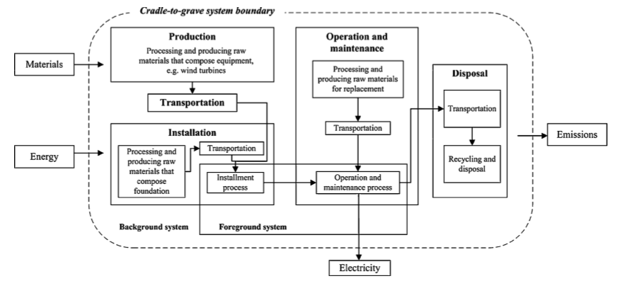
Figure 3: System’s input and outputs ()
The first stage of the production is initiating from raw materials extraction and production, including mining and processing. Materials used mainly are steel, cast iron, copper, aluminum, glass fiber, reinforced plastic (prepreg) and auxiliary material. ((1)) Onshore and offshore blades differentiate significantly in material at their foundation, where onshore wind turbines consist of concrete based foundation, with small percentage of reinforced steel, in contrast with offshore wind turbines, where the foundation consists mainly of steel structures, specially design to allow wear and corrosion resistance. Blades differ in the type of coating.
The next stage of the production is the actual turbine manufacturing, which is a result of a gate – to – gate analysis, since material produced or extracted is entering the manufacturing process, to give shape to the final parts of the system (tower, rotor, blade). At the end of this stage the parts are ready to be transported to the work site. The main environmental burden of this stage is the energy consumed during production, to reach the final parts.
Transportation is also a process causing high environmental footprint. The main transportational burden happens after final part production at the factory, aiming to transport them to the final work site. The burden is associated with the energy required to cover the distance and is calculated as the product of the distance in km, by the weight in kg. However, in calculations is also accounted the energy needed to transfer the material to the production site, before the final part reaches the wind farm. Onshore turbine blades and foundations are mainly transported with trucks to the farm. The average distance travelled for the nacelle, the hub and the blades is about 10,000 km. Offshore turbines are manufactured in locations with good proximity to ports, in order to avoid any complications, and finally they are shipped to the offshore farm, using two self – propelled jack – ups, operating as barge, equipped with cranes to allow the installation of preassembled parts. The average distance from shore in the case of locating offshore turbines assuming deep water installation is 70 km from shore. In Table 4, data concerning distance travelled in km and vehicle used are provided.
Table 4: Distance travelled in km and used vehicle- onshore, offshore ((1))
| Turbine | Part | Truck (km) | Boat (km) | Train (km) |
| Onshore 2MW | Tower | 72.4 | – | – |
| Nacelle | 1953 | – | – | |
| Rotor | – | 404 | ||
| Offshore 5MW | Tower | – | 70 | – |
| Nacelle | – | 3687 | – | |
| Rotor | – | 1084 | – |
The next step is the installation of the wind turbine. Onshore wind turbines require conventional construction equipment for setup. Offshore wind turbines require further equipment. The reverse but identical procedure is required while dismantling the units before disposal. Τable 5 and Table 6 provide data about the entire fuel consumption considering both transportation and setup needs.
Table 5: Fuel requirements for transportation and setup on site for onshore wind turbines ((1))
| Equipment | Fuel consumption (L) |
| Generator | 418 |
| Crane | 620 |
| Truck | 145.4 |
| Forklift | 64 |
| Excavation digger | 44.1 |
| Σ = 1291.5 |
Table 6: Fuel requirements for transportation and setup on site for offshore wind turbines ((1))
| Equipment | Fuel consumption (L) |
| Boat | 1536.7 |
| Self -propelled jack up barge | 21330 |
| Crane | 620.1 |
| Forklift | 64 |
| Hydraulic Hammer | 44.3 |
| Σ = 23595.1 |
During operation and maintenance technical studies prove that the energy requirements, thus the environmental footprint, are very low. Regular inspection and maintenance procedures account only as 2% of the overall energy requirements, including activities, such as oil change, lubrication, etc. The current study is assuming no serious parts replacement due to unexpected, early failure, except of the gearbox being replaced after 10 years of usual lifetime. Routine inspection is assumed to be carried out every year and oil change every three years.
The last stage of the analysis is concerned about the end of the life of the turbine. Wind turbines are consisted of steel at about 70% of their total mass, and typically are installed using tubular steel structures that may be recycled several times. Table 7 presents the disposal methods for all materials used in wind turbine production. Disposal methods for the given material is assumed to be common for onshore and onshore wind turbines
Table 7: Disposal and recycling strategy per material
| Material | Disposal |
| Iron | 90% Recycling |
| Fiberglass | 100% Landfill |
| Oil | 100% Combusted |
| PVC | 100% Landfill |
| Aluminim | 55% Recycling |
| Steel | 90% Recycling |
| Copper | 90% Recycling |
| Concrete | 100% Landfill |
Table 8 provides a summary of the accounted energy requirements as a function of material, production method and stage of life. For the end of life of onshore turbines two scenarios have been considered, recycling and landfill. The most energy consuming and CO2 emitting stage is clearly the material extraction phase, followed in case of recycling by the end of life procedure.
Table 8: Energy requirements and CO2 emissions – landfill, onshore wind turbines ((2))
| Phase | Energy (kJ) | CO2 (kg) |
| Material | 1.7594E +010 | 1.2546E +006 |
| Manufacture | 1.3593E +009 | 107669.7209 |
| Transport | 2.4336E +008 | 17278.6954 |
| Use | 1.6778E +008 | 11912.5577 |
| End of Life | 2.1826E +008 | 13095.780 |
| Total | 1.9583E +010 | 1.4045E +006 |
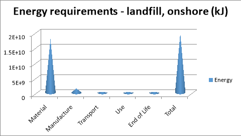
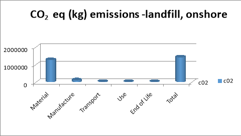
Figure 4: Energy requirements and CO2 eq, landfill – onshore
Table 9: Energy requirements and CO2 emissions – recycling, onshore wind turbines ((2))
| Phase | Energy (kJ) | CO2 (kg) |
| Material | 1.7594E +010 | 1.2546E +006 |
| Manufacture | 1.3593E +009 | 107669.7209 |
| Transport | 2.4336E +008 | 17278.6954 |
| Use | 1.6778E +008 | 11912.5577 |
| End of Life | -6.8515E +009 | -495917.2797 |
| Total | 1.2513E +010 | 895503.8906 |
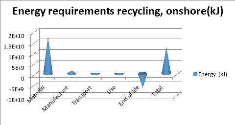
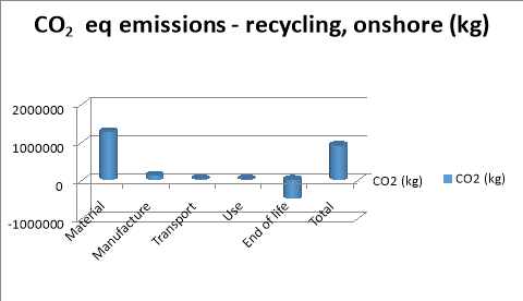
Figure 5: Energy requirements and CO2 eq, recycling – onshore
Table 10: Total Energy input and output – onshore wind turbines
| Landfill | Recycling | |
| Total Construction Energy Input (KWh) – TCE | 5.41 x 10^6 | 3.47x 10^6 |
| Capacity factor 40% applied, Annual Energy Output (KWh/year) – AEO | 7 x 10^6 | 7 x 10^6 |
| Total energy output in 25 years (KWh) -TE | 175 x 10^6 | 175 x 10^6 |
| TCE / TE | 32.32 | 50.43 |
| Energy Pay back Time – TCE / AEO (months) | 9.27 | 5.94 |
At the offshore scenario, the total energy demands are reduced at about 30% while considering recycling, thus this is the only case to be studied, since the proposal of landfill would be highly environmental aggravating. Per 1KWh output the energy input without recycling would be 192 kJ, while the required energy input with recycling is reduced to 135 kJ, meaning more than 30% reduction. ((3))
Table 11: Energy required and CO2 emissions per KWh of output energy – offshore wind turbines ((1))
| Phase | Energy (kJ) | g CO2 |
| Material and Manufacturing | 62.15 | 5.1 |
| Transport | 42.1 | 3.8 |
| Use | 11.55 | 0.25 |
| End of life | 19.2 | -1.75 |
| Total | 135 | 7.4 |
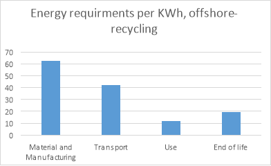
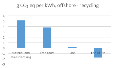
Figure 6: Energy requirements and CO2 eq, recycling – offshore
Table 12: Total Energy input – output, offshore (sub 3)
| Total Construction Energy Input (kWh) -TCE | 2.9 x 10 ^7 |
| Capacity factor 47% applied, Annual Energy Output (KWh/year) – AEO | 11.4 x 10 ^6 |
| Total energy output in 25 years (KWh) -TE | 285 x 10^ 6 |
| TCE / TE | 18.7 |
| Energy Pay back Time – TCE / AEO (months) | 9.1 |
- Impact assessment (ISO 14042)
The impact assessment of the current study presents the most severe environmental hazards, produced per KWh of electricity generated by wind turbines. Those are common for both onshore and offshore facilities and they differ only in the respective amount. The higher environmental impacts have been present at the early stages of production, transportation and installation. The environmental impact during operation and maintenance is almost negligible. End of life, or else called, disposal / recycling is also of minor importance.
Environmental impacts do not have hazardous reflections at the restricted area close to the unit. Affected zones are human health, natural environment without borders and natural resources. Figure 7 shows the affected zone of each impact category, as well as, their interconnection and relation.
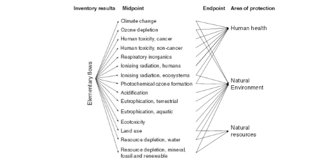
Figure 7: Impact categories and affected zones ((6))
For onshore wind turbines the major environmental impact categories, accompanied with their respective quantities are presented in Table 14.
Table 14: Environmental impact categories per kWh of electricity generated, onshore ((4))
| Indicator | Unit | Quantity |
| Global Warming Potential (GWP) | kg CO2 | 8.65E-03 |
| Abiotic Depletion (ADP elements) | kg Sb | 2.49E-07 |
| Abiotic Depletion (ADP fossil) | MJ | 9.34E-02 |
| Acidification Potential (AP) | kg SO2 | 7.25E-05 |
| Eutrophication Potential (EP) | kg PO4 | 5.45E-05 |
| Human Toxicity Potential (HTP) | kg DCB | 5.46E-02 |
| Ozone Layer Depletion Potential (ODP) | kg R11 | 3.68E-08 |
| Terrestrial Eco-toxicity Potential (TETP) | kg DCB | 1.30E-03 |
| Freshwater Aquatic Eco-toxicity Potential (FAETP) | kg DCB | 3.33E-02 |
| Marine Aquatic Eco-toxicity Potential (MAETP) | kg DCB | 4.78E+01 |
| Photochemical Ozone Creation Potential (POCP) | kg C2H4 | 6.36E-06 |
The following chart provides an insight towards the contribution of the major stages of the lifespan of the onshore wind turbines towards each impact category: ((4))
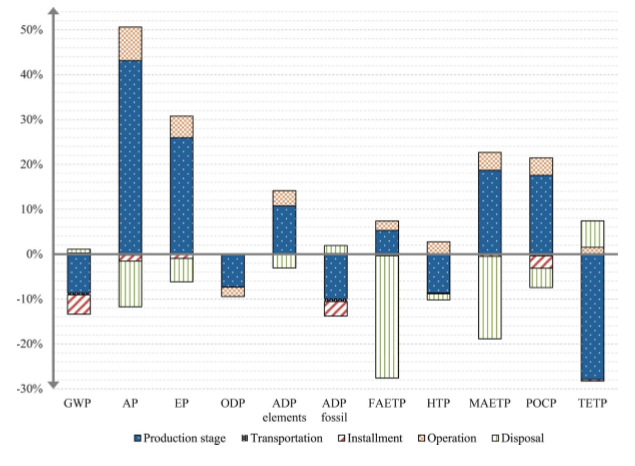
Figure 8: Impact categories and individual effect during lifespan correlation, onshore ((4))
Table 15: Environmental impact categories per kWh of electricity generated, offshore ((5))
| Indicator | Unit | Quantity |
| Global Warming Potential (GWP) | kg CO2 | 3.2E-03 |
| Abiotic Depletion (ADP elements) | kg Sb | 2.4E-05 |
| Acidification Potential (AP) | kg SO2 | 3.2E-05 |
| Eutrophication Potential (EP) | kg PO4 | 3.4E-06 |
| Human Toxicity Potential (HTP) | kg DCB | 2.3E-02 |
| Ozone Layer Depletion Potential (ODP) | kg R11 | 3.68E-08 |
| Terrestrial Eco-toxicity Potential (TETP) | kg DCB | 6.5E-05 |
| Freshwater Aquatic Eco-toxicity Potential (FAETP) | kg DCB | 3.2E-02 |
| Marine Aquatic Eco-toxicity Potential (MAETP) | kg DCB | 4.78E+01 |
| Photochemical Ozone Creation Potential (POCP) | kg C2H4 | 1.7E-06 |
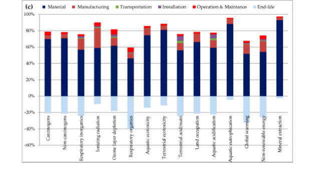
Figure 9: Impact categories and individual effect during lifespan correlation, offshore ((1))
As the wind turbines studied in the current LCA, both onshore and offshore, contain blades composed by glass fiber as main material, a qualitative analysis of glass fiber production gives a clear insight of each process towards to the respective environmental impact. Fiberglass is considered to be one of the major parameters affecting the environmental profile of the studied wind turbines, since the blades are the main performance indicator of the turbines.
|
Raw Material Handling |
Crushing |
Weighing |
Mixing |
Melting |
Spinning |
Forming |
Curing |
Cooling |
Weaving |
|
| AP | ||||||||||
| ATP | ||||||||||
| EP | ||||||||||
| GWP | ||||||||||
| HTP | ||||||||||
| NRADP | ||||||||||
| ODP | ||||||||||
| POCP | ||||||||||
| Noise, Vibration | ||||||||||
| Odour | ||||||||||
| Biodiversity loss | ||||||||||
| Fugitive Dust | ||||||||||
| High Impact | ||||||||||
| Low Impact | ||||||||||
| No Impact |
Figure 10: Qualitative analysis of impact assessment for fiber glass production
- https://www.gdrc.org/sustdev/concepts/17-lca.html (sub1)
- https://www.e-education.psu.edu/egee401/sites/www.e-education.psu.edu.egee401/files/A%20Brief%20History%20of%20Life-Cycle%20Assessment.pdf (sub2 )
- http://www.ourenergypolicy.org/wp-content/uploads/2014/06/turbines.pdf
- https://www.siemensgamesa.com/en-int/products-and-services/offshore (sub 3)
Cite This Work
To export a reference to this article please select a referencing stye below:
Related Services
View all


DMCA / Removal Request
If you are the original writer of this essay and no longer wish to have your work published on UKEssays.com then please click the following link to email our support team:
Request essay removal