Vehicle Anti-lock Braking Traction Control
| ✅ Paper Type: Free Essay | ✅ Subject: Engineering |
| ✅ Wordcount: 3486 words | ✅ Published: 30 Aug 2017 |
‘Understand vehicle anti-lock braking traction control and Integrated dynamic stability control systems’.
Introduction
I have learned that the anti-lock braking systems (ABS) are electronic systems that monitor and control wheel slip during vehicle braking, as well as the ABSs can improve vehicle control during braking, and reduce stopping distances on slippery road surfaces by limiting wheel slip and maintaining lockup. Also, the reducing wheel spin improves the vehicle stability and control during braking, since stability increases as wheel slip decreases.
Assessment Criteria 2.1
It is correct to assume that due to the increased loads on steered wheels and wider tyres there is a large effort required at the steering wheel it makes the driver ability to control the car very tiring and difficult, especially when steering the vehicle at very low speeds like parking and reversing. There are improvements such as an increase in the mechanical efficiency of the steering system or lowering steering box ratios to help reduce the driver fatigue, however if the steering mechanism is not limited the increased number of turns made by the steering wheel to move it from lock to lock becomes disturbing. When the steering effort exceeds a safe maximum, a method must be found and power-assisted steering (PAS) seems to answer certain requirements:
1. It must be ‘fail-safe’, if the power system fails, the driver must still be able to retain effective control.
2. The degree of assistance must be proportional to the effort applied by the driver, and the driver must be able to continue to have the ‘feel’ of the wheels.
On light vehicles, hydraulic and electronic power the assistance is used to help the driver steer the vehicle. Hydraulically operated power-assisted systems run by a constant pressure or constant flow layout. The diagram below, shows the essential components required to operate a constant flow system with rack-and-pinion steering system. In addition to the normal steering components, the system requires:
– A pump, and
– A control valve. Hillier’s (2012)
Diagram 1 showing the PAS System (Power-Assisted Steering) in a hydraulic system:
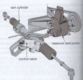
Hillier’s (2012)
The hydraulic pump shown has the reservoir for the hydraulic fluid as the contained component of the design. The reservoir supplies the hydraulic fluid to the power-steering control valve that is joined to the pinion shaft. When it is driven on a straight ahead position the valve is placed in a neutral position, allowing the fluid to go around continuously through the hydraulic circuit. The fluid pressure acting on the power cylinder is equal so no assistance is given to the steered wheels. When the steered wheels are turned through the action of the driver giving movement to the pinion shaft and control valve, then the torsion bar connected to the control valve to the pinion shaft will twist.
The torsional movement of the control valve will direct fluid pressure from the pump through to one side of the power cylinder. When the fluid pressure is acted upon on the power cylinder it creates a force to the side of the cylinder providing the necessary assistance to the driver in turning the steered wheel, the control valve normally sits in the neutral position, thus providing equal pressure to both sides of the power cylinder and requiring no longer the assistance is required. Hillier’s (2012)
The hydraulic pump is an eccentric rotor or also named a vane-type driven by the vee belt from the engine crankshaft. Some of the hydraulic pumps are put in place onto the new cars that are electronic to improve on the performing of the engine by not drawing power from the belt via the crankshaft. The pump is supplied by hydraulic fluid from either an integral reservoir or a remote arrangement. The type of fluid used is usually an automatic transmission fluid (ATF) which has low viscosity.
The pressure is created in the pump by the rotation of the vane or rotor, the fluid under pressure is sent to the spool control valve. The maximum pressure that the pump can produce is normally around 7MNm squared or 1,0001bf in squared. This is controlled by a pressure relief valve. The normal pressure is generally proportional to the engine speed because of the direct linkage with the power-steering pump. Any excess pressure released by the pressure relief valve is redirected back to the fluid reservoir.
Nowadays in most modern production vehicles a far on power steering system will also include features such as a system to alter the power assistance depending on the road and engine speed. This is done by fitting a valve in the system allowing full force during low speed manoeuvring increasing the assistance for the driver. During high road speeds and engine speeds the valve will modulate the pressure through the hydraulic steering system limiting the amount of assistance and enabling the driver to feel the road and the steered wheels. Vehicle handling is very much improved and so is the stability of the car.
The control valve, shows a kind of rotary motion type control valve which is regulated by a torsion bar which is positioned between the steering shaft and the pinion of the steering box. The valve is commonly called a rotary control valve which is a shaft with a series of flutes encased by a sleeve which has the same number of internal axial grooves. The ports situated around the outside of the sleeve and shaft pass the oil from the pump supply to the lines connected to the ram chambers.
The operation principles of the PAS system provide the following control functions:
– Road speed sensitive power assistance
– Assisted steering return
Both functions are the result of the motor voltage control by the ECU. The ECU determines the voltage supply to the motor based on the following data:
– The force applied to the steering wheel by the driver
– The vehicle speed
– The steering angle position and
– The speed of steering angle change
The torque sensor measures the input force applied by the drive, when the driver turns the steering wheel the torsion bar between the two halves of the steering column will twist. The amount of twist is proportional to the force applied.
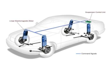
Diagram 2, The Rotary-type control valve operation
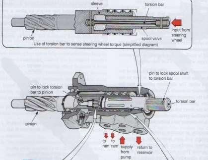
Hiller’s (2012)
Assessment Criteria 2.2
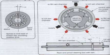
The active suspension system is now being commonly used for riding comfort, running safety, they control the vertical movement of the wheels relative to the chassis or vehicle body with an on-board system, rather than in a passive suspension in which the movement is being determined completely by the road surface. Active suspension may be generally divided into two main classes, pure active suspension and adaptive semi-active suspension. Active suspensions only vary the shock absorber firmness to match changing road conditions, the active suspension use some type of actuator to raise and lower the chassis independently at each wheel.
The technologies allow the manufacturers nowadays to achieve a greater ride of quality and car handling by keeping the tyres perpendicular to the road in corners allowing for better traction control. The on-board computer detects body movement from the sensors throughout the vehicle and using this data controls the action of the active and semi-active suspension. Active suspension eliminates body roll and pitch variation in most driving situations including cornering, accelerating, and braking.
The active suspension also known as computerized ride control have components like a computer or two ECU, adjustable shocks and springs, a series of sensors at each wheel and right through the car and an actuator or servo at each shock and spring. The components may vary slightly from manufacturer to manufacturer. The active suspension works by constantly sensing changes in the road surface and feeding that information, via the ECU to the outlying components. The components act upon the system to modify its character adjusting shock stiffness, spring rate and to improve ride performance drivability and responsiveness.
Diagram 3, Active Suspension:
Extremetech.com (2016)
The principles of operation of an active suspension relies entirely on the computer (ECU) which detects body movement from the sensors located throughout the vehicle. The hydraulic pressure to the servo is supplied by a high pressure radial piston hydraulic pump. There are 13 sensors continually monitoring the body movement and vehicle level and supply the ABS controller with new data every ten milliseconds. Four level sensors one at each wheel measures the longitudinal and transverse body acceleration. At each hydraulic cylinder a pressure sensor monitors the hydraulic pressure. As the ABS controller receives and possesses data, it operates four hydraulic servos, each mounted in series on a spring strut, besides each wheel. Almost immediately the servo regulates the suspension which generates counter forces to body lean, dive and squat during several driving manoeuvres. There is a suspension strut which consists of a steel coil spring and a shock absorber connected in parallel.
The Active Body Control system (ABC) also allows for self-levelling suspension which raises and lowers the vehicle in response to the ever-changing load. Every vehicle equipped with ABC has an ‘ABC Sport’ button which allows the driver to adjust the suspension range for different driving style preferences. The feature allows the driver ton adjust the suspension to maintain a more level ride in a more demanding driving conditions. Motor-car.co.uk (2016)
Assessment Criteria 2.3
The steering angle sensor (SAS) is a critical part of the ESC system that measures the steering wheel position angle and rate turn. A scan tool can be used to get the data in degrees. The SAS, which is located, in a sensor cluster in the steering column. The cluster always has more than one steering column. The ESC module must receive two signals to confirm the steering position. The signals are often out of phase with each other. The analog SASs are very much alike to the throttle position sensors, SASs are wired with a 5-volt reference, chassis ground and signal output and can be tested via a port under the steering column. When the steering wheel is turned, the SASs produces a signal that varies between 0 and 5 volts as the wheel is turned 360 degrees. It is possible to observe the 0 to 5-volt signal with meters connected to the SAS sensors. When the wheels are straight forward the sensors reads about 2.8v and 4v. If the readings are the same the two sensors could be shortened together. Most vehicles produce a positive voltage turning right and a negative voltage turning left. A multi-meter could be used to test the voltage signal produced by the SAS sensors. Knowyourparts.com (2016)
The self-levelling and ride control systems have fault diagnosis in most vehicles for they incorporate a self-diagnostic facility that will illuminate a malfunction indicator lamp (MIL) if a fault is detected. If you suspect a fault with a self-levelling or ride control system a visual inspection is normally conducted for wear and tear. A scan tool is connected to the diagnostic connector and fault codes are retrieved.
Diagram 4, examples of suspension system fault codes: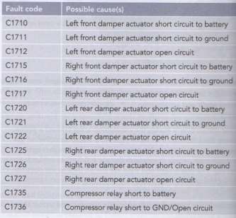 Stoakes Graham (2012)
Antilock braking systems (ABS) are electronic systems that monitor and control wheel slip during vehicle braking. ABSs may improve vehicle control during braking and reduce stopping distances on slippery road surfaces by limiting wheel slip and minimizing lockup. Reducing wheel slip improves vehicle stability and control during braking, for stability increases as wheel slip decreases. A simple braking system consists of a master cylinder and four wheel cylinders. When the brake pedal is pressed the piston in the master cylinder forces the liquid out of the cylinder. The liquid pressed the two pistons in the wheel-cylinders outwards. The two pistons push the brake shoes outwards. One major component of the anti-lock braking system includes the master cylinder, when the pedal is pressed the primary piston moves to the left, when it crosses the bypass port the liquid is forced along the pipe lines to the wheel cylinders. When the pedal is released the primary piston is moved backwards.
Diagram 5, Inside the Master Cylinder:
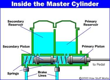
Auto.howstuffwirks.com (2016)
The principles of the ABS system are the following:
– The skidding and loss of control is caused by the locking of the wheels.
– The release and reapply of the brakes pedal will avoid the locking of the
wheels which in turn avoids the skidding.
– This is exactly what an antilock braking system does.
The pressure modulation works when the brake pedal is pumped or pulsed, the pressure is quickly applied and released at the wheels. This is called pressure modulation, which works to prevent the wheels from locking. The ABS system can modulate the pressure to the brake as often as 15 times per second. ABS precisely control’s the slip rate of the wheels to ensure maximum grip force from the tyres and therefore ensures easy manoeuvre and stability for the driver of the vehicle.
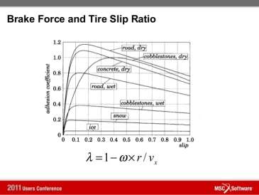
The slip rate during ABS operation varies, the target slip rate can be from 10 to 30%. 0% slip means the wheel is rolling freely, while 100% means the wheel is fully locked. A slip rate of 25% means the velocity of a wheel is 25% less than that of a freely rolling wheel at the same vehicle speed.
Diagram 6, showing a Lateral and Longitudinal Mu-Slip Curve:
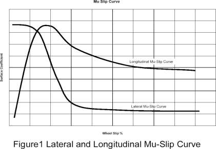
Freerebublic.com (2016)
Hydraulic components of the ABS system include an accumulator, which is used to store the hydraulic fluid to maintain high pressure in the brake system. The antilock hydraulic control valve assembly controls the release and application of the brake system pressure to the wheel brake assemblies. The booster pump is used to provide pressurized hydraulic fluid to the ABS (Antilock braking system).
The booster/master cylinder assembly is needed to modulate hydraulic pressure in the wheel circuit during the ABS operations. The fluid accumulator temporarily stores the brake fluid that is removed from the wheel brake unit during the ABS cycle. A hydraulic control unit may have one pump and one motor or it may have one motor and two pumps. The main valve is made up of a two-position valve and is opened only in the ABS mode. A modulator unit controls the flow of pressurized brake fluid to the individual wheel circuits. The solenoid valves located in the modulator unit and are electrically operated by signals from the control module.
Diagram 7, typical Toyota ABS control relay wiring diagram:
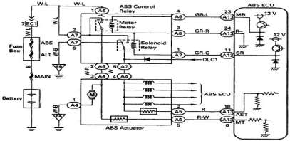
Wiringdiagrams21.com (2016)
The electrical/electronic components consist of the following:
– ABS control module, which monitors the system operation and controls
the antilock function when needed.
– Brake pedal sensor, is the function to switch on the brake lights to alert
other vehicles that the car is slowing down and is going to stop.
– The wheel speed sensor, are generally used for sensing the wheel
speed.
There are three different types of anti-lock braking system, firstly the four channel, four sensor ABS, this is the best scheme, there are speed sensors on all four wheels and a separate valve for all four wheels. Secondly, the three channel, three sensor ABS, this scheme is commonly found on pick-up trucks with four wheels ABS, has a speed sensor and a valve for each of the front wheels, with one valve and one sensor for both rear wheels. Thirdly, the one channel, one sensor ABS, has one valve which controls both rear wheels and one speed sensor located in the rear axle.
The features and benefits of ABS system include the following:
Features Benefits
– Control of steering. Increase steering ability and
vehicle stability during
braking
– Fail-safe electrical/ electronic If the electrical/electronic
System. system fails, the ABS is shut
off.
– Traction control. It is an optional feature that
controls excessive wheel
spin during acceleration.
– ABS malfunction indicator lamp. It informs the driver or
technician that there is ABS
fault.
Diagram 8, the Operation under different conditions:
Slideshare.net (2016)
The design goals of the ABS system are to:
– Attain minimum stopping distance
– Maintain stability and steering ease
The design solution includes the following:
To develop a system that rapidly modulates the braking force under hard braking conditions to:
Maintain the ideal tyre slip percentage to maximise braking force (=15%), recalling that Fbrake = Ubn.
To permit the vehicle to be steered with stability maintained by preventing skidding.
The automatic traction control system applies to the brakes when a drive wheel attempts to spin and lose traction. The system works best when one drive wheel is working on a good traction surface and the other is not. The system also works well when the vehicle is accelerating on slippery road surfaces especially when climbing hills.
Diagram 9, A block diagram of traction:
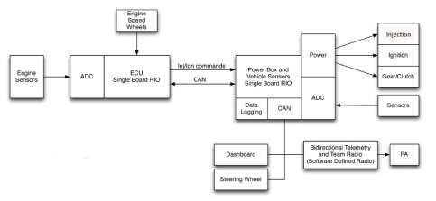
Sine.ni.com (2016)
The benefits of traction control are avoiding are:
– It improves driver safety
– Less sudden twists and turns
– Fewer slippage of the wheels
– Fewer stopping distances
– Mostly integrated with powerful cars
– Better gripping of the car.
The traction TCS control system is used to prevent wheel spin and loss of traction. These sorts of systems help to prevent the tyres from breaking loose during sudden acceleration on slick surfaces. They are usually an add on to the ESC electronic stability control system to control and restore traction on the slippery roads. The TCS and ABS systems share the same wheel speed sensors. The TCM program requires two additional solenoids in the hydraulic modulator assembly. The solenoids isolate the brake circuits to the drive wheels from the non-drive wheels during wheel spin. An electric pump and an accumulator are used to apply the wheel brake on the wheel that has lost its traction.
The systems use an actuator to reduce power at speeds above 30 mph. This is done by closing the throttle on the vehicle with electronic throttle controls retarding the timing and decreasing fuel injector pulse width. If the ABS and traction control light illuminates continuously then the system should be scanned for codes. Most of these systems have a deactivation switch if the traction control is not required. Freeasestudyguides.com (2016)
Assessment Criteria 2.3
The service and repair procedures from Land Rover Service Manual:
1. Clean the ABS sensor, smear the sensor with an anti-seize grease and
fit the sensor to the hub.
2. Fit the Allen screw securing ABS sensor and tighten to 8 Nm (6 1b.ft)
tighten to 8 Nm (6 1b.ft).
3. Secure the sensor lead to the suspension arm and suspension turret,
then connect and secure to the multi-plug. Close the cover on the
multi-plug housing.
4. Locate the wheel arch liner and secure with screws.
Service and Repair:
1. Release catch and disconnect the ABS modulator multi-plug.
2. Disconnect the multi-plug from the sensor.
3. Position the cloth under modulator to absorb the fluid spillage.
CAUTION: Brake fluid will damage paint finished surfaces. If spilled, immediately remove fluid and clean area with water. Ensure that the water does not enter modulator ports.
4. Noting their fitted positions, disconnect 6 brake pipe unions from the
Modulator.
5. Remove belt securing ABS modulator to mounting brake.
6. Release and remove the ABS modulator from mounting brackets to
Modulator and remove bracket.
Assessment Criteria 2.4
The stability control system momentarily applies the brakes at any one wheel to correct over steer or under steer. The control unit receives signals from the typical sensors plus a yaw, lateral acceleration (G-force) and steering angle sensor. The vehicle stability control system (VSC) were created to help reduce the amount of wheel slip during acceleration and in harsh driving conditions. The way stability control system works is by having a connection between the live sensors and the anti-lock brake unit. It works by the sensors getting information and processing it through the ECU and sending it to the anti-lock brake system ABS unit. By applying hydraulic pressure through the anti-lock brake-system it may alter the traction of the wheels individually.
The advantages of an integrated stability control system are:
– It allows the driver to maintain directional stability and control over
steering during braking.
– It is safe and effective.
– This automatically changes the brake fluid pressure at each wheel to
maintain optimum brake performance.
– The ABS absorb’s the unwanted turbulence shock waves and modulates
the pulses thus permitting the wheel to continue turning under maximum
braking pressure.
The disadvantages are:
– It is very costly
– The service and repair diagnosis is not simple
– Maintenance cost of a car equipped with ABS is more.
Conclusion
Statistics show that approximately 40% of automobile accidents are due to skidding. The problems commonly occur on vehicle with conventional brake systems which can be avoided by adding devices called ABS. If there is an ABS failure, the system will revert to normal brake operation. Normally, the ABS warning light will turn on and let the driver know there is a fault.
Reference
- Extremetech.com (2016) Bose’s amazing active suspension uses speaker technology [online] Available at: http://www.extremetech.com/extreme/97177-bose-active-supension-moves-toward-market/2 [Accessed: 15th March 2016]
- Freeasestudyguides.com (2016) TCS Traction Control System [online] Available at: http://www.freeasestudyguides.com/tcs-traction-control-systems.html [Accessed: 15th March 2016]
- Hillier’s (2012) Fundamentals of Motor Vehicle Technology, 6th ed. Cheltenham: London
- Motor-car.co.uk (2016) Mercedes-Benz Car Active Body Control (ABC) [online] Available at: http://www.motor-car.co.uk/susoension-types/item/14575-car-active-body-control [Accessed: 15th March 2016]
- Stoakes, Graham (2012) Principles of Light Vehicle Technology, 1st ed. Heinemann: Essex
Cite This Work
To export a reference to this article please select a referencing stye below:
Related Services
View all


DMCA / Removal Request
If you are the original writer of this essay and no longer wish to have your work published on UKEssays.com then please click the following link to email our support team:
Request essay removal