Using Ic Engine Exhaust Gas As A Energy Source For Vapour Absorption Refrigeration System
| ✅ Paper Type: Free Essay | ✅ Subject: Engineering |
| ✅ Wordcount: 7522 words | ✅ Published: 18 May 2020 |
“Using Ic Engine Exhaust Gas As A Energy Source For Vapour Absorption Refrigeration System”
Abstract
Now a day the air conditioning system of cars is mainly uses Vapour Compression Refrigerant System (VCRS) which absorbs and removes heat from the interior of the car that is the space to be cooled and rejects the heat to atmosphere. In vapour compression refrigerant system, the system utilizes power from engine shaft as the input power to drive the compressor of the refrigeration system, hence the engine has to produce extra work to run the compressor of the refrigerating system utilizing extra amount of fuel. This loss of power of the vehicle for refrigeration can be neglected by utilizing another refrigeration system i.e. a Vapour Absorption Refrigerant System. As well known thing about VAS that these machines required low grade energy for operation. Hence in such types of system, a physicochemical process replaces the mechanical process of the Vapour Compression Refrigerant System by using energy in the form of heat rather than mechanical work. This heat obtained from the exhaust of high power internal combustion engines.
List of Tables
Table 1: Comparison between Vapour Absorption and Vapour
Compression System . . . . . . . . . . . . . . . . . . . . . . . . . . . . . . . . . . . . . . . . . . . . .15
Table 2: Requirement of Material. . . . . . . . . . . . . . . . . . . . . . . . . . . . . . . . . . . . . . . . . 30
Table 3: Work Plan . . . . . . . . . . . . . . . . . . . . . . . . . . . . . . . . . . . . . . . . . . . . . . . . . . . . . . . 34
List of Figures
2.1) A typical single stage vapour compression system. . . . . . . . . . . . . . . . . . . . . . . 8
2.2) p-h diagram for VCR system. . . . . . . . . . . . . . . . . . . . . . . . . . . . . . . . . . . . . . . . . . . . . .9
2.3) Basic absorption refrigeration cycle. . . . . . . . . . . . . . . . . . . . . . . . . . . . . . . . . . . . . .11
2.4) VARS cycle. . . . . . . . . . . . . . . . . . . . . . . . . . . . . . . . . . . . . . . . . . . . . . . . . . . . . . . . . . . . . . 13
2.5) Condenser. . . . . . . . . . . . . . . . . . . . . . . . . . . . . . . . . . . . . . . . . . . . . . . . . . . . . . . . . . . . . . .16
2.6) Capillary tube. . . . . . . . . . . . . . . . . . . . . . . . . . . . . . . . . . . . . . . . . . . . . . . . . . . . . . . . . . . 16
2.7) Evaporator. . . . . . . . . . . . . . . . . . . . . . . . . . . . . . . . . . . . . . . . . . . . . . . . . . . . . . . . . . . . . .17
2.8) Generator. . . . . . . . . . . . . . . . . . . . . . . . . . . . . . . . . . . . . . . . . . . . . . . . . . . . . . . . . . . . . . . 18
3.1) Ammonia water vapour absorption system. . . . . . . . . . . . . . . . . . . . . . . . . . . . . . .20
3.2) Enthalpy-concentration diagram. . . . . . . . . . . . . . . . . . . . . . . . . . . . . . . . . . . . . . . . . 23
3.3) Generator. . . . . . . . . . . . . . . . . . . . . . . . . . . . . . . . . . . . . . . . . . . . . . . . . . . . . . . . . . . . . . . .26
3.4) Condenser coil. . . . . . . . . . . . . . . . . . . . . . . . . . . . . . . . . . . . . . . . . . . . . . . . . . . . . . . . . . . 27
3.5) Evaporator coil. . . . . . . . . . . . . . . . . . . . . . . . . . . . . . . . . . . . . . . . . . . . . . . . . . . . . . . . . . .28
3.6) Capillary tube. . . . . . . . . . . . . . . . . . . . . . . . . . . . . . . . . . . . . . . . . . . . . . . . . . . . . . . . . . . . 28
3.7) Experimental Set-up. . . . . . . . . . . . . . . . . . . . . . . . . . . . . . . . . . . . . . . . . . . . . . . . . . . . . .29
Chapter 1 Introduction
1.1 Definition Of Project
This model is refrigerant model which is used in cooling for an automobile vehicle. It is comprises of process such as condensation, expansion, evaporation and compression. Vapour Absorption Refrigerant System (V.A.R.S) uses ammonia, water as a refrigerant agent which provides space cooling in an automobile cabin.
1.2 General Description
A heat engine is a system that performs the conversion of heat or thermal energy to mechanical work. Examples of everyday heat engines include the steam engine, the diesel engine, and the gasoline (petrol) engine in an automobile. Heat engines are designed to produce useful work only. The efficiency of a modern internal combustion engine is about 37% in a normal passenger car spark ignition engine. The energy in the form of heat is rejected by means of exhaust, circulating cooling water, lubrication oil & radiation. Due to green house effect & changing environment and atmospheric effect, the air conditioning of the moving vehicle has become a necessity now a day. The refrigerating effect is done by either Vapour Compression Refrigeration System (VCRS )and Vapour Absorption Refrigeration System (VARS).
1.3 Objective of Project
The significance of the work is that it will provide space cooling for the truck driver and thereby enhances his performance and efficiency without affecting performance of the engine essentially the fuel economy. Further the vapour absorption cycle use non CFC refrigerant and thereby have little effect on environment. This system leads to better utilization of source energy and is not location limited. It could be operable in remote locations, disaster relief situations, or anywhere a diesel generator is in operation. In all instances, the implementation of a waste heat recovery system would reduce the electrical demand for space conditioning.
1.4 Heat recovery and availability from I.C.engine.
Waste heat is heat, which is generated in a process by way of fuel combustion or chemical reaction, and then dumped into the environment even though it could still be reused for some useful and economic purpose. This heat depends in part on the temperature of the waste heat gases and mass of rate of exhaust gas. Waste heat losses arise both from equipment inefficiencies and from thermodynamic limitations on equipment and processes. For example, consider internal combustion engine approximately 30% to 40% is converted into useful mechanical work. The remaining heat is expelled to the environment through exhaust gases and engine cooling systems. It means approximately 60% to 70% energy losses as a waste heat through exhaust. Exhaust gases immediately leaving the engine can have temperatures as high as 450C-600C. Consequently, these gases have high heat content, carrying away as exhaust emission. Efforts can be made to design more energy efficient engine with better heat transfer and lower exhaust temperatures; however, the laws of thermodynamics place a lower limit on the temperature of exhaust gases.
1.5 Need.
In India road transport is a major mode of transport for goods over large distances. The atmospheric temperature in some parts of India touches 45C .In
Such condition studies show that the temperature inside the cabin of a transport truck even exceeds 55C. The operation in such hot condition for the truck driver is extremely difficult. Further this extreme heat reduces the working efficiency of the drivers and delays the transport duration over the road. The delay further affects the economy, which is unacceptable. So some measures have to be taken to reduce the temperature inside the cabin of the truck and to provide comfort to the driver. Considering present energy crises all over the world, it is very much necessary to explore new technology and potential to satisfy the need of society. At the same time the efficient management of the production and energy conservation is also equally important.
For automobile air conditioning normally vapour compression refrigeration cycle is used. The cycle run on engine power and consumes around 10% of the total power produced by the engine and thereby increases the fuel consumption .In case of truck large amount of heat as input around 25% of the total heat supplied is going away with exhaust gases at very high temperature and around 25% is going away with cooling water. So if this waste heat can be utilized for powering an air conditioning system it will be economical and the fuel energy can be used effectively. Using Ic Engine Exhaust Gas As A Energy Source For Vapour Absorption Refrigeration System.
Chapter 2 Literature Review
There are various researchers who have contributed their work for vapour absorption refrigeration system. The researchers have proposed novel techniques with suitable implementations. Now we concentrate on few researchers works as given below.
2.1 General Approach
Satish K. Maurya said that it is possible to design an automobile air conditioning system using engine heat based on Vapour Absorption Refrigeration System. Also from the Environmental point of view this system is echo-friendly as it involves the use of Ammonia as a refrigerant which is a natural gas and is not responsible for OZONE layer Depletion. In this way we can concluded, technically, that out of the total heat supplied to the engine in the form of fuel, approximately, 30% to 40% is converted into useful mechanical work; the remaining heat is expelled to the environment through exhaust gases and engine cooling systems, resulting in to entropy rise and serious environmental pollution, so it is required to utilized waste heat into useful work. The recovery and utilization of waste heat not only conserves nuel (fossil fuel) but also reduces the amount of waste heat and greenhouse gases damped to environment. The study shows the availability and possibility of waste heat from internal combustion engine, also describe loss of exhaust gas energy of a internal combustion engine. Possible methods to recover the waste heat from internal combustion engine and performance and emissions of the internal combustion engine. Waste heat recovery system is the best way to recover waste heat and saving the fuel.
According to Hui Tong Chua and Anutosh Chakraborty, The formulation of specific heat capacity of a single component adsorbent + adsorbate system is one of the basic foundations of any adsorbate-adsorbent thermodynamic analysis. This would be useful in the design and analysis of solid-gas absorption in cooling applications such as adsorption chiller, adsorption cry coolers, and infrared detectors cooling.
Lambart and Jones said that to provide air cooling for the driver of a truck is never given importance in India; the basic reason is the use of available methods of air cooling affects the fuel consumption and the initial cost of the truck. For automobile air conditioning normally vapour compression refrigeration cycle is used. The cycle run on engine power and consumes around 10% of the total power produced by the engine and thereby increases the fuel consumption. Till date, 1 TR VAR system has been neither built practically nor simulated for analyzing the performance of the system because of its low C.O.P. Due to this reason, no information is available regarding the performance of 1 TR VAR system. The work carried out in this project holds significance not only because it shows the practicability of fabricating a 1 TR VAR system for providing cabin cooling of truck by using engine exhaust but also it makes available the information about the performance of such a system under different operating conditions.
2.2) Vapour Compression Refrigeration System
2.2.1) Description of Vapour Compression Refrigeration System
By and large refrigeration means, expelling the warmth from a space so that the space gets to be colder than the encompassing. Naturally the warmth streams from hot locale to chilly district. Be that as it may, in a refrigeration framework the warmth is expelled from frosty area and rejected into a hot district, subsequently the icy locale gets to be colder and hot areas get to be more sizzling.
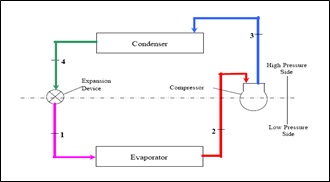 Figure2.1: a typical, single-stage vapour-compression system

Figure2.2: p-h diagram for VCR system
The vapor-pressure utilizes a coursing fluid refrigerant as the medium which assimilates and expels heat from the space to be cooled and along these lines rejects that warmth somewhere else. Figure1 portrays a normal, single-stage vapor-pressure framework. Every single such framework have four segments: a compressor, a condenser, a warm development valve (likewise called a throttle valve), and an evaporator. Circling refrigerant enters the compressor in the thermodynamic state known as an immersed vapor and is compacted to a higher weight, bringing about a higher temperature too. The hot, compacted vapor is then in the thermodynamic state known as a superheated vapor and it is at a temperature and weight at which it can be consolidated with either cooling water or cooling air. That hot vapor is steered through a condenser where it is cooled and dense into a fluid by coursing through a curl or tubes with cool water or cool air streaming over the loop or tubes. This is the place the circling refrigerant rejects heat from the framework and the rejected warmth is diverted by either the water or the air (whichever may be the situation).
The dense fluid refrigerant, in the thermodynamic state known as an immersed fluid, is next steered through an extension valve where it experiences a sudden diminishment in weight. That weight diminishment results in the adiabatic glimmer vanishing of a piece of the fluid refrigerant. The auto-refrigeration impact of the adiabatic glimmer dissipation brings down the temperature of the fluid and vapor refrigerant blend to where it is colder than the temperature of the encased space to be refrigerated.
The vapor-weight uses a coursing liquid refrigerant as the medium which ingests and ousts heat from the space to be cooled and thusly rejects that glow elsewhere. Figure1 portrays a common, single-stage vapor-weight system. Each and every such structure have four sections: a compressor, a condenser, a warm augmentation valve (in like manner called a throttle valve), and an evaporator. Coursing refrigerant enters the compressor in the thermodynamic state known as a drenched vapor and is compacted to a higher weight, achieving a higher temperature as well. The hot, stuffed vapor is then in the thermodynamic state known as a superheated vapor and it is at a temperature and weight at which it can be thick with either cooling water or cooling air. That hot vapor is coordinated through a condenser where it is cooled and thick into a liquid by coursing through a circle or tubes with cool water or cool air gushing over the twist or tubes. This is the spot the streaming refrigerant rejects heat from the system and the rejected warmth is occupied by either the water or the air (whichever may be the circumstance).
The merged liquid refrigerant, in the thermodynamic state known as a splashed liquid, is next guided through an advancement valve where it encounters a startling diminishment in weight. That weight abatement results in the adiabatic burst vanishing of a bit of the liquid refrigerant. The auto-refrigeration effect of the adiabatic gleam vanishing cuts down the temperature of the liquid and vapor refrigerant mix to where it is colder than the temperature of the encased space to be refrigerated.
The chilly blend is then steered through the loop or tubes in the evaporator. A fan flows the warm air in the encased space over the curl or tubes conveying the cool refrigerant fluid and vapor blend. That warm air vanishes the fluid piece of the icy refrigerant blend. In the meantime, the flowing air is cooled and in this way brings down the temperature of the encased space to the fancied temperature. The evaporator is the place the flowing refrigerant retains and uproots heat which is consequently dismisses in the condenser and exchanged somewhere else by the water or air utilized as a part of the condenser.
To finish the refrigeration cycle, the refrigerant vapor from the evaporator is again a soaked vapor and is directed once more into the compressor.
2.2.2) DRAWBACKS OF VAPOUR COMPRESSION REFRIGERATION SYSTEM
Though this system is the most efficient of all the refrigeration system still it has some disadvantages:
- A vapour compression system has more, tear and noise due to moving parts of the compressor.
- The amount of work required to compress the gas in the compressor is very high.
- It strictly depends on electric power or mechanical power and cannot be used at places where these recourses are not available.
- The capacity of vapour compression system drops rapidly with lowered evaporator pressure.
-
The performance of a vapour compression system at partial loads is poor.
In the vapour compression system, it is essential to superheat the vapour refrigerant leaving the evaporator so that no liquid may enter the compressor.
2.3) Vapour Absorption Refrigeration System

Figure 2.3) Basic Absorption Refrigeration System
The vapor assimilation refrigeration is one of the most seasoned routines for delivering refrigerating impact. The guideline of vapor assimilation was initially found by Michael Faraday in 1824 while performing an arrangement of analyses to melt certain gasses. The principal vapor ingestion refrigeration machine was produced by a French researcher Ferdinand Carre in 1860. This framework may be utilized as a part of both the household and expansive mechanical refrigerating plants. The refrigerant, ordinarily utilized as a part of a vapor retention framework is smelling salts. The vapor retention framework uses heat vitality, rather than mechanical vitality as in vapor pressure frameworks, keeping in mind the end goal to change the states of the refrigerant required for the operation of the refrigeration cycle. The capacity of a compressor, in a vapor pressure framework, is to pull back the vapor refrigerant from the evaporator. It then raises its temperature and weight higher than the cooling specialists in the condenser so that the higher weight vapors can reject heat in the condenser. The fluid refrigerant leaving the condenser is currently prepared to extend to the evaporator conditions. This refrigeration framework comprises of a condenser, an extension valve and an evaporator like a Vapor Compression Refrigeration System. Be that as it may, the compressor of the Vapor Compression Refrigeration System is supplanted by a generator, a safeguard and a little pump. A Vapor Absorption Refrigeration System uses two or more than two liquids which has high liking towards one another, in which one is the refrigerant and the other is the retentive.
The procedure of working of this refrigeration framework is that a blend of refrigerant and a safeguard (i.e. solid arrangement) is pumped from the safeguard utilizing a little pump to the generator. The generator is the fundamental unit of the entire refrigeration framework. This is the spot where warmth is supplied to the solid arrangement. Because of the supplied warmth to the blend in the generator the refrigerant is isolated from the solid arrangement and structures vapor. The staying powerless arrangement streams back through a restrictor into the safeguard. The refrigerant is then permitted to go through a condenser where the warmth of the vapor is removed and the refrigerant temperature is conveyed to the room temperature. This cooled refrigerant is then gone through a development gadget where amid extension the temperature of the refrigerant falls beneath the climatic temperature. This chilly refrigerant is then gone through an evaporator from where the refrigerant assimilates warmth and produces refrigerating impact. The refrigerant originating from the evaporator is hot and it is gone to the safeguard. The powerless arrangement originating from the generator blends with the refrigerant originating from the evaporator in the safeguard because of high fondness towards one another for the two liquids, thus shaping an in number arrangement. The framed solid arrangement is again pumped into the generator and the cycle rehashes itself.

2.4 ) VARS Cycle
The vapor assimilation refrigeration framework includes every one of the procedures in the vapor pressure refrigeration framework like pressure, buildup, extension and vanishing. In the vapor retention framework the refrigerant utilized is smelling salts, water. The refrigerant gets consolidated in the condenser and it gets dissipated in the evaporator. The refrigerant produces cooling impact in the evaporator and discharges the warmth to the climate by means of the condenser. The significant distinction between the two frameworks is the system for the suction and pressure of the refrigerant in the refrigeration cycle. In the vapor pressure framework, the compressor sucks the refrigerant from evaporator and packs it to the high weight. The compressor additionally empowers the stream of the refrigerant through the entire refrigeration cycle. In the vapor assimilation cycle, the procedure of suction and pressure are completed by two unique gadgets called as the safeguard and the generator. Consequently the safeguard and the generator supplant the compressor in the vapor ingestion cycle. The retentive empowers the stream of the refrigerant from the safeguard to the generator by retaining it. Another significant distinction between the vapor pressure and vapor assimilation cycle is the strategy in which the vitality data is given to the framework. In the vapor pressure framework the vitality data is given as the mechanical work from the electric engine keep running by the power. In the vapor assimilation framework the vitality data is given as the warmth. This warmth can be from the abundance steam from the procedure or the high temp water. The warmth can likewise be made by different sources like characteristic gas, lamp fuel, and radiator and so forth however these sources are utilized just as a part of the little frameworks.
2.3.1) Ammonia-Water Absorption Cycle
An Absorption Cycle can be viewed as a mechanical vapour-compression cycle, with the compressor replaced by a generator, absorber and liquid pump. Absorption cycles produce cooling and/or heating with thermal input and minimal electric input, by using heat and mass exchangers, pumps and valves. The absorption cycle is based on the principle that absorbing ammonia in water causes the vapour pressure to decrease. The basic operation of an ammonia-water absorption cycle is as follows. Heat is applied to the generator, which contains a solution of ammonia water, rich in ammonia. The heat causes high pressure ammonia vapour separate from the solution. Heat can either be from combustion of a fuel such as clean-burning natural gas, or waste heat from engine exhaust, other industrial processes, solar heat, or any other heat source. The high pressure ammonia vapour flows to a condenser, typically cooled by outdoor air. The ammonia vapour condenses into a high pressure liquid, releasing heat which can be used for product heat, such as space heating. The high pressure ammonia liquid goes through a restriction, to the low pressure side of the, cycle. This liquid, at low pressures, boils or evaporates in the evaporator. This provides the cooling or refrigeration product. The low pressure vapour flows to the absorber, which contains a water-rich solution obtained from the generator. This solution absorbs the ammonia while releasing the heat of absorption. This heat can be used as product heat or for internal heat recovery in other parts of the cycle, thus unloading the burner and increasing cycle efficiency. The solution in the absorber, now once again rich in ammonia, is pumped to the generator, where it is ready to repeat the cycle.
2.3.2) Description of Vapour Absorption Refrigerant System
An absorption refrigerator is a refrigerator that uses a heat source (e.g., solar, kerosene-fuelled flame, waste heat from factories or district heating systems) to provide the energy needed to drive the cooling system. In the early years of the twentieth century, the vapour absorption cycle using water-ammonia systems was popular and widely used. Ammonia-water combination possesses most of the desirable qualities which are listed below:
- • 1m3 of water absorbs 800m3 of ammonia (NH3).
- • Latent heat of ammonia at -15ᴼC = 1314 kJ/kg.
- • Critical temperature of NH3 = 132.6ᴼC.
The NH3-H2O system requires generator temperatures in the range of 125°C to 170°C with air cooled absorber and condenser and 80°C to 120°C when water-cooling is used. These temperatures cannot be obtained with flat-plate collectors. The coefficient of performance (COP), which is defined as the ratio of the cooling effect to the heat input, which vary between 0.6 to 0.7. Ammonia is highly soluble in water.
2.4) Comparison between Vapour Absorption and Vapour Compression System
|
No. |
Vapour Absorption system |
Vapour Compression System |
|
1. |
Uses low grade energy like heat. Therefore, may be worked on exhaust systems from I.C engines, etc. |
Using high-grade energy like mechanical work. |
|
2. |
Moving parts are only in the pump, which is a small element of the system. Hence operation is smooth. |
Moving parts are in the compressor. |
|
3. |
The system can work on lower evaporator pressures also without affecting the COP. |
The COP decreases considerably with decrease in evaporator pressure. |
|
4. |
No effect of reducing the load on performance. |
Performance is adversely affected at partial loads. |
|
5. |
Liquid traces of refrigerant present in piping at the exit of evaporator |
Liquid traces in suction line may damage the compressor |
|
6. |
Automatic operation for controlling the capacity is easy. |
It is difficult. |
Table: 1) Comparison between Vapour Absorption and Vapour Compression System
2.5) Components
1) Condenser:

Fig. 2.5) Condenser
Just like in the traditional condenser of the vapour compression cycle, the refrigerant enters the condenser at high pressure and temperature and gets condensed.
2) Capillary tube:

Fig . 2.6 capillary tube
A capillary tube is a long, narrow tube of constant diameter. The word “capillary” is a misnomer since surface tension is not important in refrigeration application of capillary tubes. Typical tube diameters of refrigerant capillary tubes range from 0.5 mm to 3 mm and the length ranges from 1.0 m to 6 m. The pressure reduction in a capillary tube occurs due to the following two factors:
i) The refrigerant has to overcome the frictional resistance offered by tube walls.
This leads to some pressure drop.
ii) The liquid refrigerant evaporates into mixture of liquid and vapour as its pressure reduces. The density of vapour is less than that of the liquid. Hence, the average density of refrigerant decreases as it flows in the tube. The mass flow rate and tube diameter (hence area) being constant, the velocity of refrigerant increases since the increase in velocity or acceleration of the refrigerant also requires pressure drop. Several combinations of length and bore are available for the same mass ow several combinations of length and bore are available for the same mass ow rate and pressure drop. However, once a capillary tube of some diameter and length has been installed in a refrigeration system, the mass ow rate through it will vary in such a manner that the total pressure drop through it matches with the pressure difference between condenser and the evaporator. Its mass ow rate is totally dependent upon the pressure difference across it; it cannot adjust itself to variation of load effectively.
3) Evaporator:

Fig 2.7 Evaporator
The refrigerant at very low pressure and temperature enters the evaporator and produces the cooling effect. In the vapour compression cycle this refrigerant is sucked by the compressor, but in the vapour absorption cycle, this refrigerant flows to the absorber that acts as the suction part of the refrigeration.
4) Absorber:
The safeguard is a kind of vessel comprising of water that goes about as the Absorbent and the past ingested refrigerant. Hence the safeguard comprises of the powerless arrangement of the refrigerant (smelling salts) and permeable (water). At the point when smelling salts from the evaporator enters the safeguard, it is consumed by the permeable because of which the weight inside the safeguard decreases further prompting more stream of the refrigerant from the evaporator to the safeguard. At high temperature water ingests lesser alkali, henceforth it is cooled by the outside coolant to build it smelling salts retention limit. The introductory stream of the refrigerant from the evaporator to the safeguard happens on the grounds that the vapor weight of the refrigerant-permeable in the safeguard is lower than the vapor weight of the refrigerant in the evaporator. The vapor weight of the refrigerant-permeable inside the spongy decides the weight on low-weight side of the framework furthermore the vaporizing temperature of the refrigerant inside the evaporator. The vapor weight of the refrigerant-permeable arrangement relies on upon the way of the retentive, its temperature and focus. At the point when the refrigerant entering in the safeguard is consumed by the spongy its volume diminishes, in this way the pressure of the refrigerant happens. In this way safeguard goes about as the suction a portion of the compressor. The warmth of retention is likewise discharged in the safeguard, which is uprooted by the outside coolant.
5) Pump:
When the absorbent absorbs the refrigerant strong solution of refrigerant- absorbent (ammonia-water) is formed. This solution is pumped by the pump at high pressure to the generator.
6) Generator:

Fig. 2.8 Generator
The refrigerant-smelling salts arrangement in the generator is warmed by the outer wellspring of warmth. This is can be steam, boiling point water or whatever other suitable source. Because of warming the temperature of the arrangement increments. The refrigerant in the arrangement gets vaporized and it leaves the arrangement at high weight. The high weight and the high temperature refrigerant then enters the condenser, where it is cooled by the coolant, and it then enters the extension valve and afterward at last into the evaporator where it creates the cooling impact. This refrigerant is on the other hand consumed by the feeble arrangement in the safeguard. At the point when the vaporized refrigerant leaves the generator powerless arrangement is left in it. This arrangement enters the weight decreasing valve and after that back to the safeguard, where it is prepared to assimilate crisp refrigerant. Along these lines, the refrigerant continues rehashing the cycle. The weight of the refrigerant is expanded in the generator, thus it is thought to be identical to the pressure a portion of the compressor.
2.6 Motivation
During the training in GSECL, Surat, a technician named Nikhil Chaudhary suggested us to work on using waste energy of exaust gases. So we thought it can be used in VARS. In that, the various gas is used in generator for heating purpose. We thought that we can use exhaust gas of IC engine which having heat energy bus losses in atmosphere as a wastage. So we discuss with our faculty to implement it in real. Using Ic Engine Exhaust Gas As A Energy Source For Vapour Absorption Refrigeration System.
Chapter 3 Basic Design Consideration
3.1 Design Considerations for Ammonia-Water System

Fig 3.1 Ammonium-water vapour absorption system.
3.1.1 Properties of Ammonia and Safety Concerns
Smelling salts is a normally happening substance that is created and utilized as a part of extensive amounts (in the only us 20 million tons for each year IPCS, alkali wellbeing and security guide, publ. World wellbeing organization. Customized on substance security, Geneva, 1990) for horticulture as compost and as the source material for strands, plastics and touchy .thusly it is delivered in extensive amounts by rail and ship. Smelling salts is additionally utilized as a cleaning and de – scaling operators and sustenance added substances. Alkali is a dry gas of stream thickness at room temperature with an impactful odor. It has relative atomic mass of 17.03 and is lighter than air and climatic conditions. It can be put away and transported as a fluid under a weight of 1 MPa 25C. The basic purpose of alkali is at 132:30_C and 11.3 MPa. The basic thickness is 235 kg/m3 since smelling salts is profoundly dissolvable in water producing NH+4 and OH particles, it responds rapidly with bodily fluid layers. In any case, it is not consumed through the skin. It can be noticed by people in convergence of not very many ppm at around 50 ppm, the smell is verging on excruciating. This is likewise the fixation range (25ppm) to which long haul introduction is constrained from a word related wellbeing perspective, (IPCS,1990,ammonia wellbeing and security, Geneva )at high measurements alkali presentation can be deadly. Alkali is combustible and hazardous in the scope of 16 to 25% volume. (IPCS, 1990, smelling salts wellbeing and security, guide, publ. World wellbeing organization. Modified on substance security, Geneva) in air. The solid smell of alkali can be seen as a benefit. It is self disturbing. Indeed, even little break in framework are effortlessly seen and hence a noteworthy motivating force exists for right on time repairs and steady support. One technique for break location is to utilize wet marker paper, which will rapidly change its shading once it is presented to air with a couple ppm of smelling salts content. Nonetheless, conventional hole recognition gadgets such cleanser (or air pocket) arrangements don’t work following the smelling salts is broken down in the water without making air pocket
3.1.2 Water Content of the Refrigerant Vapour
The principal vital distinction is the vapor weight of alkali/water blends contrasted with that of water/lithium bromide. Here, alkali is the refrigerant. The ordinary breaking point is the 33:350_C. What’s more, in this way the weight of such frameworks at the temperatures typically experienced in aerating and cooling and refrigeration applications is moderately high. The weight is practically identical to vapor pressure frameworks that use R-22 as the refrigerant. The high vapor weight prompts rather little pipe measurements, and generally minimized warmth trade as contrast with Water/LiBr. A second vital distinction is that the retentive (water) has a vapor weight that is not insignificant in respect to that of alkali. As an outcome, the vapor produced in the desorber contains a sure measure of water. (The mass portion relies on upon the mass division of the fluid blend in the desorber, the temperature and the desorber configuration. Any water contained in the desorber vapor is hindering to the execution of the framework). The water will go with the vapor into the condenser and after that into the evaporator where the water has a tendency to aggregate if a poor heater outline is utilized. The vapor leaving the evaporator is rich in alkali. In spite of the fact that regardless it contains some water, the alkali mass portion of the vapor is extensively higher than that of the vapor leaving the desorber. Along these lines water will stay in the evaporator. On the off chance that no different measures are taken the evaporator temperature must be expanded significantly to dissipate the remaining water-rich arrangement.
An aggregation of water will prompt diminishing in evaporator weight which thusly will influence the safeguard conditions. As the water amasses in the evaporator the weight drops for a consistent evaporator temp which is settled by the application. The safeguard has either to be cooled to a lower temperature or the mass division of the arrangement needs to change to lower smelling salts content. Accepting that the desorber temperatures don’t change, the condenser temperature must drop which is typically precluded by the cooling water temp accessible to the condenser. an outcome the high weight level must be raised and the desorber temp will increment too. As the water keep on amassing in the evaporator the working states of the whole framework float and operation at configuration conditions is unrealistic. Restricted of averting unreasonable water gathering is to deplete it occasionally into the safeguard. However this technique speaks to loss of productivity in 2 ways. To start with the water was dissipated in the desorber requiring desorber warmth information, yet it doesn’t vanish in the evaporator; along these lines it doesn’t give to the cooling limit. Second it contains a lot of alkali that is held as fluid, intensifying this impact
3.1.3 Material Consideration for Ammonia-Water System
Alkali is a decent dissolvable for copper. In this way the utilization of any copper or copper-containing material is unimaginable. Involvement in the research center demonstrates that even chromium-plated metal parts are helpless to smelling salts consumption. The most widely recognized material for the development of alkali water frameworks is steel or stainless steel. At the point when steel is the material of decision, consumption inhibitors are required for most applications. These are salts that are included little amounts (1% by weight or so.).They structure a defensive oxide layer on the metal surface so that there is no immediate contact with the working liquid. The impact of these salts on the thermodynamic properties of the working liquid is generally disregarded. Customarily, the consumption inhibitors are salts that contain substantial metals. These are being banned by the U.S., Environmental Protection Agency and producers’ end up expecting to grow new, ecologically satisfactory substitutions. The warm conductivity of steel is around one tenth of that of copper. Along these lines the warmth exchange resistance of the divider material may never again be unimportant. Since smelling salts has moderately high vapor weight, the machines are not as vulnerable to execution debasement because of vicinity of no condensable gasses as water-lithium bromide frameworks. Then again it is never the less great practice to keep all non condensable out of the framework.
3.2 Mathematical Modeling
The operating pressures at which the system is working needs to be determined to carry on further calculations, using an enthalpy concentration chart. Once the pressure of the condenser (Pc) and the pressure of the evaporator (Pe) are determined the corresponding points can be fixed on the chart as shown in _g. The various other points and condition lines for components like absorber, generator, heat exchangers etc can be subsequently fixed.
- Condenser Pressure (Pc)
The pressure to be maintained in the condenser for changing the phase of ammonia vapours into ammonia liquid depends on type of condensing medium used and its temperature

Figure 3.2: Enthalpy-concentration diagram.
- Evaporator pressure (Pe)
The evaporator pressure can be fixed according to the minimum temperature required to be maintained in the evaporator chamber. The minimum temperature attained is not a designing criterion in this system. The pressure maintained in the evaporator should be as close to the atmospheric pressure as possible, because maintaining a higher pressure is a difficult and costly affair. Moreover it also has leakage problems and the unit needs to be hermetically sealed. The evaporator pressure is kept equal to the atmospheric pressure (1 bar), to ensure design economy. Now the points of condenser pressure and evaporator pressure can be plotted on the pressure enthalpy chart as points 1, 2, 3 and 4.
Point 1 represents pure NH3 saturated vapour at condenser pressure Pc and concentration C=1. Point 2 represents pure NH3 saturated liquid at (Pc) and C=1. This point is marked in liquid region.
Point 2 coincides with point 3 as 2-3 is a throttling process in which enthalpy remains constant.
Point 3 represents the condition of pure NH3 (wet) but at pressure (Pe) and C=1.
Point 4 represents the condition of pure NH3 at pressure ((Pe) these are saturated vapours which absorbs heat in evaporator and converts from wet vapour to saturated vapour. This point is marked in vapour region. The enthalpies at all points can be noted from the chart.
The refrigerating effect produced or the heat absorbed by ammonia refrigerant
in the evaporator is Qe= (h4 – h3)KJ/Kg of ammonia. Say the mass flow rate of
Ammonia in the evaporator be Mr.
Point 8 represents the hot weak liquid having concentration C inside the generator.
Point 6: This is the condition of the aqua solution whose concentration C5= 0.518, but the pressure is increased from Pe to Pc as it passes through the pump. Point 6 coincides with point 5 on the C-h chart as enthalpy does not change when the aqua pressure increase passing through the pump.
Point 7: Its concentration C5 remains same as well as pressure remains same as Pc. Now the point 7 can be marked on the C-h diagram as pressure at 7 and C7 are known.
Now join points 8 and 7 and extend till it cuts the Y axis (enthalpy) at a as shown in figure, then join point and 5 and extend till it cuts the vertical line passing through 8. This also decides the position of point 9 and 10.
Point 9: This shows the condition of weak liquid coming out of the generator. So enthalpy is reduced. Hence, point 9 can be marked as the concentration does not change.
Point 10: The point 10 represents the same enthalpy as 9 but at reduced pressure Pe.
3.3 Design of Components
3.3.1 Design Consideration in Absorber
The absorber arrangement consists of the tank and the pump system.
As, V = (π/4) d2 L
d = diameter
L = Length
Heat removed in absorber tank is given by,
Qa = (h4 – ha) Mr
Mr = mass flow rate of refrigerant
3.3.2 Design Consideration in Generator
The generator pipe receive rich water ammonia solution at the bottom via the pump, as the generator body is heated the vapour generated are sent to the condenser section via the top hole where as the lean water ammonia solution is sent back to the absorber via the central hole. Generator module comprises of three parts are the heat pipe module with spiral fins, heat pipe and the generator body or pipe.
Heat required in generator is given by,
Qg= (h12 – ha)Mr

Figure 3.3 Generator
3.3.3 Design Consideration in Condenser
The Condenser coil is connected to the condenser end via capillary where as the other end is connected to the generator.
Heat reject in Condenser is given by,
Qc = (h1 – h2) Mr
For calculating dimension we use,
Qc = U A
T
Qc = U π D L (T1 – T2)
Take, U = Overall heat transfer coefficient

Figure 3.4 Condenser Coil.
3.3.4 Design Consideration in Evaporator
The Evaporator coil is connected to the condenser end via capillary where as the other end is connected to the absorber tank.
Heat dissipated in evaporator coil is given by,
Qe= (h4 – h3)Mr
For getting temperature difference We use,
Qe = U A
T
Qe = U
D L
T
U = Overall heat transfer coefficient

Figure 3.5 Evaporator Coil.
3.3.5 Design Consideration in Capillary Tube
The capillary tube is used as the restriction between the condense and the evaporator end to get the refrigeration effect. Now, Head loss due to sudden contraction is given by,
hc = [V2/2g] [(1/Cc)-1]2
Where, Cc = Coefficient of contraction
As, m =
A V

Figure 3.6 Capillary Tube.
As, we know that,
Head loss is given by,
h = (4 f L V2) / (2 g d)
3.3.6 Theoretical Coefficient of performance
The Theoretical Coefficient of performance is given by,
(C:O:P:)th = Qe/Qg = heat rejected in evaporator / heat supplied to generator

Figure 3.7 Experimental set-ups.
Chapter 4 Requirement of Material
|
Sr.No. |
Description |
Quantity |
Material |
|
1) |
Absorber Tank |
01 |
Ms |
|
2) |
Generator |
01 |
Al |
|
3) |
Evaporator |
01 |
Cu |
|
4) |
Condenser Coil |
01 |
Cu |
|
5) |
Evaporator Coil |
01 |
Cu |
|
6) |
Capillary Tube |
01 |
Cu |
|
7) |
Condenser Fan |
01 |
Std. |
|
8) |
Pump |
01 |
Std. |
|
9) |
Base plate |
01 |
Ms |
Table 2 Required Materials
Chapter 5
Advantages & Limitations
5.1 Advantages
1) Heat energy can be recovered from exhaust gas of the vehicle.
2) No refrigerant compressor is required.
3) It can save the electricity.
4) No moving part except pump-motor, which is comparatively smaller than compressor system.
5) Quiet in operation, low maintenance cost.
6) Reduced noise pollution.
7) No extra work is required for the working of the refrigerating unit.
8) Reduction in weight of unit.
9) Reduction in capital cost.
10) Reduction in fuel cost.
11) Reduced atmospheric pollution.
12) Reduced maintenance.
5.2 Limitations
Though the system has a large number of advantages, there are also some disadvantages. These are:
1) Refrigerating effect will be reduced or will be difficult to produce should the vehicle be at rest or in a very slow moving traffic condition.
2) Cooling effect can be achieved after starting of some time.
3) Accommodation of the system on the vehicle is also a big task.
4) The refrigerating effect produced using a Vapour Absorption Refrigeration System is less compared to a Vapour compression Refrigeration System.
Chapter 6 Conclusion
As in India, heavy duty transport vehicle does not given any importance of Air conditioning system due to its cost. Moreover this energy is totally wasted. So we can take steps toward using this waste heat energy. And we have reached at the level to utilize waste heat into creating the refrigeration effect. For this purpose the vapour absorption system is more suitable without affecting the vehicle’s efficiency.
Work Plan
|
Month |
Activity |
Status |
|
July |
Project selection |
|
|
August |
Literature review |
|
|
September |
Details of components |
|
|
October |
Basic Design |
|
|
November |
Creating Model |
|
|
December |
Creating Model |
|
|
January |
Finalizing Model |
|
|
February |
Testing |
Table 3: Work Plan
References
[1] Alam S, 2006, A Proposed model for “Utilizing Exhaust Heat to run Automobile Air-conditioner”, the 2nd Joint International Conference on Sustainable Energy and Environment 21-23 November 2006, Bangkok, Thailand.
[2] P. Sathiamurthi, “Design and Development of Waste Heat Recovery System for air Conditioning”, Unit European Journal of Scienti_c Research, Vol.54 No.1 (2011), pp.102-110, 2011.
[3] S. Karellasa, A.-D. Leontaritisa, G. Panousisa , E. Bellos A, E. Kakaras, “Energetic And Exergetic Analysis of Waste Heat Recovery Systems” In The Cement Industry, Proceedings of ECOS 2012 – The 25th International Conference On Effciency, Cost, Optimization, Simulation And Environmental Impact of En-
ergy Systems June 26-29, 2012, Perugia, Italy.
[4] A Textbook of Refrigeration And Air Conditioning by R.S.Khurmi & J.K.Gupta, Chapter-07, Page no.273-291, 2014.
[5] A Textbook of Fluid mechanics And Hydraulic Machines by R.K.Bansal,
Chapter-11, Page no.461-553, 2005.
[6] A Textbook of Engineering Heat And Mass Transfer by M.M.Rathore, Chapter-
05, Page no.263-357, 2012.
Cite This Work
To export a reference to this article please select a referencing stye below:
Related Services
View all


DMCA / Removal Request
If you are the original writer of this essay and no longer wish to have your work published on UKEssays.com then please click the following link to email our support team:
Request essay removal