Three-Dimensional Grade Control in Road Construction
| ✅ Paper Type: Free Essay | ✅ Subject: Engineering |
| ✅ Wordcount: 2833 words | ✅ Published: 30 Aug 2017 |
Three-Dimensional Grade Control in Road Construction using Unmanned Aerial Vehicle
Introduction
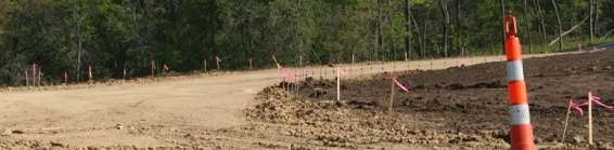
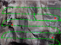
Contractors have used grade stakes installed on the side of the road at intervals of 100 feet for the vertical grade of the finished ground surface in road construction. The grade stakes are measured based on control points(CPs) which are reference points and markers established by surveyors at the design phase. By using the grade stakes, the contractors align the grade elevation with regulated tolerances which are typically less than 0.05 feet for subgrade and 0.02 feet for roadway surface (Missouri Highways and Transportation Commission 2016). The contractors confirm the final construction layout including as-built cross sections, which are measured by a total station or conventional survey methods such as a level, theodolite, and transit at intervals of 500 feet. The final products should be in reasonably close conformity with the design plans and specifications (Floyd et al. 2013).
|
|
|
Figure 1: The conventional grade control using grade stakes (Missouri Highways and Transportation Commission 2016) |
However, in many cases, the contractors have experienced unsuspected discrepancies between the as-designed model and the as-built model, which cause the project cost and time overrun (Pitman 2001). These discordances could be derived from technical issues or human matters that are issues among people such as a lack of coordination and communication between designers and contractors (Arain et al. 2004). While the problems caused by human issues could be solved easily by involving the contractors and designers as coordinators, the resolving the technical problems, such as a measurement error, still remain challenges because the conventional grade control methods use only a few points to build a final grade layout, which can cause considerable errors at the non-measured area. For this reason, many researchers have studied on the application of new technologies such as a global positioning system (GPS), robotic total station (RTS), and terrestrial laser scanning (TLS) to obtain dense points for the grade control. Despite all these efforts, the contractors are still using the traditional methods for grade control because of the disadvantages of the new approaches regarding the economic and usability. In this regard, unmanned aerial vehicle (UAV) is the most reasonable way to overcome such shortcomings (Nex and Remondino 2014). The photogrammetry using UAV is a time-competitive method to generate a digital surface model (DSM) which enables contractors to obtain the dense point cloud of the long-strip roadway construction site without intervals (Chiabrando et al. 2009). Moreover, the UAV allows the user to avoid working in hazardous environments (Barry and Coakley 2013). With such advantages, several researchers apply the UAV to roadway construction, especially for surveying earthwork projects (Siebert and Teizer 2014). The current accuracy of the UAV photogrammetry, however, does not completely meet the particular requirements in road construction such as the grading tolerance which is less than 0.05 feet. This study, therefore, reviews the current state of the three-dimensional grade control in road construction and presents a best practice for applying the UAV for the construction by providing a way to develop the accuracy of the UAV photogrammetry. Moreover, this study verifies the improved accuracy through the field test at an ongoing highway construction site in Georgia, the United States.
This study has reviewed current studies on the 1) grade control methods in road construction using dense point clouds, 2) applications of UAV for highway construction, and 3) accuracy of UAV photogrammetry.
Current study on the grade control in roadway construction
As mentioned above, the contractors today perform the grade control in a conventional manner using grade stakes and cross sections because those methods don’t require a specialty. However, such methods are conducted sparsely at regular but widely spaced intervals, which can give rise to substantial errors when the contractors build a successive three-dimensional as-built model. To avoid this, many researchers have studied on the way to create a 3D as-built model without intervals as below.
3D grade control using GPS installed on the construction equipment
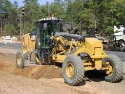
The real-time kinematic (RTK) GPS technology provides a location information for a dynamic motion in real time. The advent of the RTK-GPS technology enables the users to control the machine’s blade systemically and to build 3D as-built model automatically (Stewart, 2006). For this reason, many global GPS manufacturers, such as Topcon, Trimble, and Leica, present automatic 3D grade control technologies as seen in Figure 2. According to a final report on “Implementation of GPS Controlled Highway Construction Equipment” in the University of Wisconsin, the use of the GPS to guide construction equipment is time-efficient and cuts costs (Vonderohe 2007).
|
|
|
Figure 2: GPS controlled roadway construction equipment |
Accordingly, many Department of Transportation (DOT) have increased the implementation of the automated machine guidance with GPS (Townes 2013). However, the vertical error of RTK-GPS is typically over 1.5 inches, and sometimes a sudden elevation shift caused by a cycle slip or multipath, which can lead to a significant discrepancy between as-design model and as-built model. Therefore, it’s impossible to fully adopt the GPS to grade control in roadway construction unless there is an enhancement of the accuracy.
Terrestrial laser scanning (TLS) for the highway construction process monitoring
The TLS, which measures the location of thousands of points each epoch at ranges of hundreds of meters, is another method to collect high dense point data. The TLS generates more accurate 3D layouts than conventional survey methods (Slattery and Slattery 2013). D. Slattery et al. (2010) demonstrate that the TLS is a feasible means to control the grade in highway construction projects and to calculate earthwork quantities (Slattery and Slattery 2010). Despite the fact that the TLS guarantees accurate point clouds, this new technology faces several operational challenges. One of the primary challenges is that it takes extremely long time to acquire the dense points. In general, the measurement using TLS takes one hour to measure the area of 20,000 square feet. Furthermore, as the scanner is installed on the ground, TLS method forms shadow zones where cannot scan due to obstacles such as trees and hills. In particular, since the roadway construction site is quite long, such drawbacks could be fatal. In this regard, the UAV, which is a less time-consuming way of measuring fields, could be an effective alternative.
Application of UAV for roadway construction
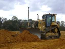
The UAV referred to as a drone, has recently begun to be applied to the construction field with the improvement of the positioning technologies and high-performance digital camera (Turner et al. 2012). With the development of the high-performance UAV, many researchers have successfully applied the UAV for the 3D modeling of the construction site and the measurement of earthwork quantities. S. Siebert and J. Teizer (2014) presents a practice for the application of UAV to construction survey for earthmoving of the construction site. They assert that the UAV technology is a cost- and time-effective alternatives to ground-based survey applications (Siebert and Teizer 2014). Furthermore, M. Daakir et al. (2015) describe that the UAV equipped with GPS receiver can achieve a consistent 3D model with a relatively low cost (Daakir et al. 2015). The studies on the application of the UAV has been limited to the particular construction fields such as earthmoving project and field survey for planning the road construction because the accuracy of the photogrammetry using UAV is over two inches which exceed the tolerance for the vertical grade. Thus, the improvement of the accuracy of UAV photogrammetry is required prior to applying the UAV technology to the grade control in roadway construction.
|
|
|
Figure 3: The developed UAV systems, S. Siebert and J. Teizer (left), M. Daakir et al. (right) |
Accuracy of UAV photogrammetry
Several researchers have examined innovative ways of improving the accuracy of the UAV photogrammetry. The accuracy of the UAV photogrammetry directly depends on the ground sampling distance (GSD), which is determined by the focal length, flight altitude, and resolution of the camera. In general, higher GSD value indicates that the image would have a lower spatial resolution. Therefore, the altitude of the flight should be performed around 150 m above ground level to obtain images at the GSD of up to 10 cm. (RuzgienÄ- et al. 2015). In addition, the use of geo-referencing methods aligning UAV imagery with known points measured in advance also can improve the accuracy of the photogrammetry. J. Goncalves and R. Henriques (2015) assert that the vertical root mean square (RMS) errors of UAV photogrammetry can be decreased to 5cm by using ground control points (GCPs) as the geo-referencing (Gonçalves and Henriques 2015). However, a minimum of three GCPs are required for the geo-referencing, and generally, more than nine GCPs should be appeared on the imagery to retain redundancy for least squares regression. Moreover, the method that aligns the imagery known as “Image registration” causes a systematic error which is a cumulative error. In particular, since the road construction site requires extremely long longitudinal measurement, the registration error is theoretically increased in direct proportion to the length of the construction site (Zheng et al. 2016). This study, therefore, proposed a method to correct the systemic error by originating the position of the flying UAV with dual-frequency RTK-GPS and resection method.
|
|
|
Figure 4: The GCPs that J. Goncalves and R. Henriques (2015) used |
Methodology
This chapter enumerates the methodology for applying the UAV photogrammetry to the grade control in road construction as follows.
- Type of UAVs
- Ground Sampling Distance (GSD)
- Ground Control Points (GCPs)
- Positioning of the UAV using space resection method
- 3D model generation
- Verification
Types of UAV
The type of UAVs is classified into three categories: fixed wing type, rotary wing type, and hybrid wing type integrated the fixed wing and rotary type. Fixed wing UAVs have characteristics that they have a simple mechanism and more efficient aerodynamics which allows the fixed wing UAV to fly longer duration at higher speeds than the rotary wing. On the contrary, the rotary wing UAVs have a relatively more complicated structure which may infer that they have lower speed and shorter flight range than fixed wing. The advantages of the rotary wing are that they can conduct vertical takeoff and landing (VTOL) and hovering. The fixed/rotary hybrid UAV has both characteristics of the fixed wing type and rotary wing type. The hybrid UAVs can perform VTOL and hovering and fly with little power like the fixed wing UAV. Table 1 shows the differences between the fixed wing and rotary drones. Since the roadway construction site is quite long and doesn’t have vertical obstacles, the fixed wing type of UAV is most appropriate for the surveying the road construction area.
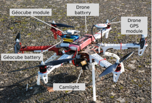
Most UAV for the land survey is equipped with single frequency GPS receiver for positioning of the flying vehicle. In general, the vertical accuracy of the single frequency GPS is compromised. For this reason, this study suggests mounting a dual frequency GPS on the UAV to improve their positioning accuracy. The vertical accuracy of the dual frequency RTK-GPS is known to be lower than 2cm in general circumstances. This study might use virtual reference station (VRS), which facilitate the RTK/GPS based on National Continuously Operating Reference Station (CORS).
|
Table 1 |
||
|
The differences between fixed wing type and rotary type |
||
|
Fixed wing |
Rotary wing |
|
|
Purpose |
Mapping |
Small area Mapping Inspection |
|
Application |
Land surveying (rural) GIS Construction |
Inspection Real estate Surveying (urban) |
|
Flight Speed |
High |
Low |
|
Coverage |
Large |
Small |
|
Flight Duration Times |
Long |
Short |
|
Wind Resistance |
High |
Low |
|
VTOL |
X |
O |
|
Hovering |
X |
O |
Ground Sampling Distance (GSD)
As mentioned above, GSD value is related to the flight level, focal length, and resolution of the camera. Since the GSD value directly affects the results of the photogrammetry, it is important to determine the flight altitude. For a given flying height H, the GSD will be given by
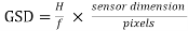
Where f is the lens focal length, and H is the flight altitude. Typically, in the case of the GSD of 5 cm, the standard deviation of 1 pixel in the parallax may result in a standard deviation of approximately 5 ~ 10 cm in the elevation error. The flight altitude also affects the overlapping rate which is related to the accuracy of the photogrammetry. That is to say, for a given focal length and resolution of the camera, increasing the altitude will increase overlap rate and GSD. Since it is possible to fly the UAV at low altitude in roadway construction site where is a barrier-free area, this study limits the flight height to 100 m or less to maintain the GSD of under 5cm. Although flying at low altitude can cause little overlap rate, the matter of overlapping can be solved by taking more pictures.
Ground Control Points (GCPs)
In the photogrammetry for field surveying, establishing a network of the ground control points
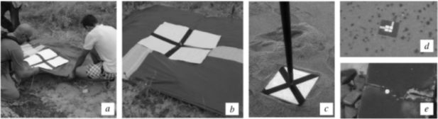
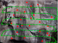
The GCPs installed on the field is employed for the geo-referencing. Although the bundle image adjustment needs to have at least three GCPs, it is necessary to have 9 or more GCPs for providing enough redundancies for the least square adjustment. The GCP photogrammetric targets should be visible in the pictures and have about 5 ~ 10 times the dimensions of the GSD. Since the accuracy of the GCPs is crucial for the accuracy of the final results, the position of the GCPs should be measured precisely by total station or post-processing GPS. M.Chahbazi et al. (2015) state that although a large number of well-distributed GCPs as seen in Figure 5 (left) guarantees the highest accuracy, if it is impossible due to the field conditions, the best practice is to install the GCPs near the ends of the flight strips to be visible in several images from two closest strips. Furthermore, placing the GCPs with height variation is beneficial for the vertical adjustment of the UAV imagery.
|
|
|
Figure 5: The methods to set up the GCPs in the article of M.Chahbazi et al. (2015) (left) when there are enough GCPs, and (right) if not. |
According to the construction survey manual of U.S. Department of Transportation (DOT), contractors or sub-contractors should establish control points (CPs), which are semi-permanent reference points built beside the construction site at intervals of 500 feet, to align the horizontal distribution and vertical elevation. Since these CPs are measured from the second-order benchmark, which has a ratio of closure of 1:10000, it is possible to construct accurate GCPs.
Positioning of the UAV using space resection method
The position of flying UAV has been determined from the GPS embedded on the UAV until now. However, the accuracy of the GPS depends on the satellite signal which sometimes includes serious errors such as cycle slip or multipath caused by the environmental conditions. Moreover, time synchronization between the GPS and images from the Camera can also cause several errors. In this regard, this study proposes a new positioning method that improves the accuracy of the photogrammetric results by applying space resection method. The resection method is to determine an unknown point from two known points. This measurement method is usually used when measuring the location of the device such as total station or theodolite.
|
|
|
Figure 7: The concept of the space resection for UAV photogrammetry (Ref. https://dronemapper.com/uas_photo-grammetry_processing) |
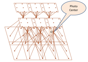
The space resection requires at least two known ground control points per an image, but this study used five ground control points for the least square adjustment. The accuracy of the space resection only depends on the range error of the camera, which is much more accurate than RTK-GPS, and therefore this study expects an improvement in the positioning accuracy of the operating UAV
As-built 3D model generation
The stereo images extracted from UAV photogrammetry go through the image matching process. The image matching process is usually classified into correlation based method and feature-based method. The correlation based method has various computational processes because they conduct the image matching with all area and pixels. In contrast, since the feature based method adjusts images with edges or corners in the pictures, the processing is faster than the correlation based method. Scale-invariant feature transform (SIFT) is one of the most widely used features detecting method. The SIFT algorithm extracts key points from overlapped area, and align the images by using descriptors which are created from the extracted key points. The 3D structure is built by structure from motion (SfM) algorithm, which is a method to generate 3D structure by calculating the pose of the camera from 2D images. Most commercial software today has used the feature-based image matching and SfM algorithm to create a 3D model. One of the commercial software is Agisoft PhotoScan which conduct image matching with the feature-based method. This study generates the as-built model of the roadway construction site based on the DSM generated from the Agisoft PhotoScan. The final as-built 3D model would be compared to the as-design model. An essential issue in this step is to synchronize the coordinates system used in both as-design model and as-built model. For this reason, it is essential that both models should be on the geographic information system (GIS) based on a global coordinate system.
Verification
|
Table 2 |
|||||
|
The whole process of this study |
|||||
|
Step 1 |
Step 2 |
Step 3 |
Step 4 |
Step5 |
|
|
Objectives |
Planning UAV operation |
Establishing GCPs |
Obtaining images from UAV |
Generating 3D model |
Verification |
|
Details |
– GSD – Flight Altitude – Overlapping rate |
– The number – Location |
– Resection – QC of images |
– SIFT, – SfM – DSM |
– Field Test – Error Assessment |
Cite This Work
To export a reference to this article please select a referencing stye below:
Related Services
View all


DMCA / Removal Request
If you are the original writer of this essay and no longer wish to have your work published on UKEssays.com then please click the following link to email our support team:
Request essay removal