Specifications of Damage Assessment Technique
| ✅ Paper Type: Free Essay | ✅ Subject: Engineering |
| ✅ Wordcount: 1724 words | ✅ Published: 31 Aug 2017 |
Specifications of Damage Assessment Technique
Damage Tolerance (DT), is the ability of a material to function and resist fracture after a permanent change/defect has taken place for a given period of time. The Damage Tolerance is an essential attribute of a structural component, whose failure could result in catastrophic loss of life or property.
- Damage Tolerance Analysis
The DT addresses two points concerning an initially defected/damaged structure.
- First, it determines fracture load for a specified defect size. Meaning that the load where material failure occurs, when a specified defect size, exists is determined.
- Second, it predicts the required length of time for a sub-critical defect to grow to the size that causes fracture at given load. In this case, it is assumed that the defect can extend and propagate in a sub-critical manner1.
The determination of fracture/failure load for a defected component will be the primary target of the DT analysis that will be carried out for the project’s needs.
To apply the DT method, the fatigue target stress levels need to be calculated. The last can be derived from the ultimate allowable stress levels. The ultimate allowable stress levels can be basically determined by the loading conditions applied to the specified component. In every structural case, the specific target stress value for any given primary structural component is adjusted for its specific geometry and material properties. Therefore, the prediction of the required length of time for a sub-critical defect to grow to the size that causes fracture at given load will be attempted to be determined. Of course to achieve predicting the required length of time for a sub-critical defect to grow to the size that causes fracture at given load, the respective material data should be available.
- Damage Tolerance Analysis Procedure
It is known that a structure usually fails by one or combination of failures. These failures can be elastic /inelastic deformations, buckling, fatigue or accidental impact, etc.
In the flow chart of Figure 4.1 a possible procedure that might be adopted to carry out the numerical DT analysis of a structural component is depicted. This flow chart, as it can be seen, covers the case of static and fatigue load. Despite of this, each case can be assessed and examined individually if all the required inputs are available.

1 Damage Tolerance Analysis of Aero Structural Components, TATA


Figure 4.1: Damage Tolerance Analysis Procedure
It is intended to develop a fully parametric numerical model of the structural (metallic and/or composite) component for the DT modelling using the aid of suitable Finite Element software. The work plan is to write a scripting code in the FE software’s parametric design language to allow defect geometric characteristics (e.g. defect location, damage size etc.) and external data (e.g. geometric characteristics, material properties, loading and boundary conditions of the component) to be automatically inserted to the numerical model of the structural component.
The aim is to develop a code with the following features:
- easy data insertion by uploading the geometry of the component,
- apply loading and boundary conditions to the DT modular unit, and
- data import for different types of components with minimum modifications.
Moreover, it will be attempted to achieve a sufficient mesh density for the Finite Element model (refined FE model) that will provide adequate accuracy by minimizing the discrepancies of the results in a prescribed range. At the same time, it is desired that the model will not consumes excessive computational time and effort for its solution.
It will be attempted to incorporate an adaptive mesh routine for increasing the mesh density at the defect regions according to certain condition/criteria, such as the minimum energy condition. This technique will be employed in case that complex geometry is about to be analysed.
Eventually, a post-processing macro-routine will also be programmed to process the results from the analysis solution. A possible way for verifying whether the structural component can operate with defect or repair is required is by calculating the Margin of Safety (MS) for the examined component. Using the maximum stress (von-Mises) obtained from the numerical analysis, static margin of safety (MS) obtained for limit and ultimate loads can be calculated respectively. By employing the suitable failure criteria a possible reduction of the component’s structural strength will be defined.
- Required inputs for Damage Tolerance Analysis
In this section the inputs that will be required for carrying out the numerical structural analysis are listed in the following paragraphs. A brief explanation about each required input is also presented in order the reader to comprehend the necessity of each characteristic.
- Component’s geometric characteristics
The geometric characteristics of the component can be separated in three distinguished categories, which both of them have to be defined with accuracy. These categories are:
- component’s geometry (the geometric characteristic of the reference-no defect- component),
- type of defect, and
- geometry of the defect.
And they are explained in more detail below.
Component‘s Geometry
Initially, the geometric characteristics of the component are required for carrying out a numerical analysis that will assess the DT of the investigated component. In more detail, the geometric characteristics of the investigated component-in case of a flat plate- are its width, length, its thickness etc.
For the case where a more complex geometry needs to be investigated, CAD drawings will be required. It is preferred to provide EXIS with the drawings in electronic format in a neutral file (e.g. .igs or .stp format) to allow the smooth insertion of these file to the FE software. Additional inputs will be required, depending the case, for de-featuring the CAD model and eventually generate an equivalent simplified FE model. It is expected the last to have less elements/nodes and hence less computational demands.
Typeofdefect
The type of flaw detected by the Non Destructive procedure (e.g. crack, delaminations, etc.) will be an advantage to be known and given as input before developing the FE model for the DT analysis, Figure 4.2. It will be helpful to know the defect type DT Analysis of the structural component will examine, so the appropriate modelling procedure and discretization method in the defect’s region will be used.
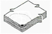

Delaminations(single-andmulti-level)Freeedgedamages(delaminations,
notches,loosefibers,etc.)
Figure 4.2: Type of defect to be analysed
DefectGeometry
It is essential when performing a numerical structural analysis of a defected component to know the geometry of the defect. Basically in this case the geometry of the defect is part of the geometry of the analysed and investigated component.
Therefore, the non-destructive method (PA or IRT) will initially detect the damage and generate an image. The image processing procedure will allow to calculate the size of the defect and its location. The geometric characteristics that are expected to extract are the area, width (w), height (h) and the coordinates of the defected area into the component. An estimation of the through thickness damage will be also required for the FE model. The last is expected to be provided by the software that will perform the non-destructive testing.
It might be necessary to model the defect using an equivalent area of a circle or rectangular, in order to avoid modelling complex defect shapes, such as of Figure 4.3. In case that this approach is utilized, a validation procedure will be performed.
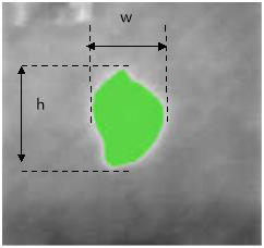
Figure 4.3: Geometrical characteristics of the defect
- Material mechanical properties
To carry out a numerical DT analysis of a component, it is necessary to insert the appropriate material models into the FE model to simulate the exact behaviour of the component and its strength. In case the metallic components are examined, the material properties that need to be available are the following:
- Modulus of Elasticity (E), and
- Poisson Ratio (ν).
Regarding composite components, monolithic CFRP is the main category that is believed that is about to be investigated, since a wide range of currently flying aircrafts, such as the Airbus 3XX family is using them.
Therefore, in case that monolithic composite material the material properties that define the material model will be inserted to the FE model. The following material properties can adequately define the behaviour of the material model.
- Material properties of the ply Eij, Gij and vij, where Eij Gij and vij is the Young, Shear modulus and Poisson’s ratio in the i,j direction respectively. The subscripts i, j can take values from 1 to 3 and they are used for defining the material coordinate system, Figure 4.4.
- Ply thickness.
- Stacking sequence and number of plies, Figure 4.4.
- Axial Strength of laminate in 1, 2 and 3 direction.
- Shear Strength of laminate in 12, 23 and 31 direction.
If the material inputs are not available from the designer of the component, then they will be taken from the open literature.
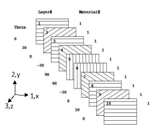
Figure 4.4: Representative stacking sequence of a CFRP composite and material coordinate system
Characteristic example of a set of three dimensional failure criteria is the maximum stress failure criteria. They are presented below (σij are the calculated layer-stress components in the (ij) direction and the denominators are the ultimate strengths in the corresponding direction).
Maximum Stress Failure Criteria:
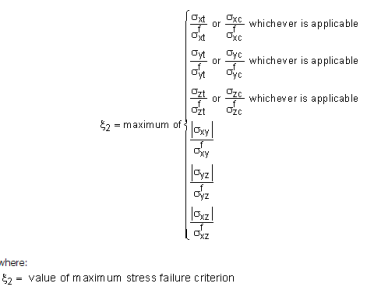
- The nominator of each ratio is the maximum stress value that is developed in the structure.
- The denominator is the strength of the material in each direction.
- Whenever the ratio is less than one then no failure occurs, otherwise material failure exists.
- It desired not having any failure when ultimate load is applied to the component.
- Restraints and Boundary conditions
The stress state of a composite structural member is strongly related with the way this member is attached to the rest of the aircraft structure. Knowing that in the area of the defect/damage stress concentration exists, the correct definition of the boundary conditions is essential. To this end, the boundary conditions of the structural component must be provided in order to apply the respective degrees of freedom/ constraints to the FE model.
- Loading conditions
For carrying out the DT analysis, the loading conditions exerted to the composite component need to be defined. It is essential for the numerical analysis the applied load to be known; hence it is a required input. In more detail the limit load that is applied to the structural component needs to be known before running the analysis.
- Additional inputs
Additional inputs might be required to perform the DT analysis of a specific component with a specific type of defect. In that case additional inputs might be needed.
Cite This Work
To export a reference to this article please select a referencing stye below:
Related Services
View all


DMCA / Removal Request
If you are the original writer of this essay and no longer wish to have your work published on UKEssays.com then please click the following link to email our support team:
Request essay removal