Radio Frequency Identification and Intelligent Parking
| ✅ Paper Type: Free Essay | ✅ Subject: Engineering |
| ✅ Wordcount: 4069 words | ✅ Published: 31 Aug 2017 |
Executive summary
This report is an introduction of two sensor related technology used in modern life. Radio frequency identification (RFID) lock system and Intelligent parking assist system (IPAS) are two topics maintained in the report. In each of the topic there will be at least three parts: history and development, principle of the technology and limitations. The aim of the report is to give reader a brief knowledge of these technology.
Radio frequency identification technology is mostly used on door lockers. These kind of products are commonly used in hotel rooms or the front gate of some buildings. The user can unlock the door by swiping a card or tag through the device without using the key. There is no physical contact though this process.
RFID lock system (Fig.1) is identified to be safer then traditional key lock system. Additionally, it is more convenient for people to use such as to open the garage door when you are in the car. RFID technology have also been used in a variety of applications: Access management, Tracking of goods, Tracking of persons and animals, Toll collection and contactless payment, Machine readable travel documents, Smart dust (for massively distributed sensor networks), Tracking sports memorabilia to verify authenticity, Airport baggage tracking logistics, Timing sporting events
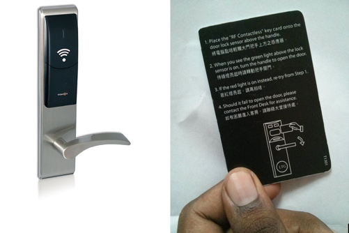
FIGURE 1:Radio frequency identification (RFID) hotel lock system
1.1 History and development
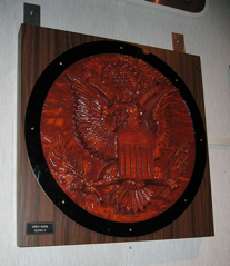
In 1945, Russian inventor Léon Theremin invented a covert listening device called ‘The Thing’ which transmit audio signal through incident radio waves. Sound waves collected by a resonant cavity microphone which oscillated the resonator, which generates the reflected radio wave. This device was not an identification tag when it was built. Due to its passive, being energized and activated by electromagnetic energy from an outside source, ‘The Thing’ is considered a original form of RFID technology, see Fig.2. [7]
 Â Â
  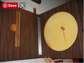
FIGURE 2: ‘the thing'(listening device) invented by Léon Theremin
Similar to ‘The Thing’, the IFF transponder, was used in World War II by the German allies to identify aircraft (Identity: Friend or Foe) [3]. Transponders are still used nowadays. In 1948 Harry Stockman predicted that “… considerable research and development work has to be done before the remaining basic problems in reflected-power communication are solved, and before the field of useful applications is explored.”[4] is another early work exploring RFID.
Mario Cardullo’s device a passive radio transponder with memory, patented on January 23, 1973, was the first true prototype of modern RFID[8]. The initial device designed as a toll device was first demonstrated in 1971 to the New York Port Authority and other potential user. It was passive, powered by the interrogating signal, with 16 bit memory. The basic Cardullo patent take RF, sound and light as transmission media. The original business plan was targeted to transportation (automotive vehicle identification, automatic toll system, electronic license plate, electronic manifest, vehicle routing, vehicle performance monitoring), banking (electronic check book, electronic credit card), security (personnel identification, automatic gates, surveillance) and medical (identification, patient history) in 1969.
In 1973, Steven Depp, Alfred Koelle, and Robert Frayman performed an early demonstration of reflected power (modulated backscatter) RFID tags, both passive and semi-passive at the Los Alamos National Laboratory. [5] The portable system operated at 915 MHz and used 12-bit tags. Today, the majority of UHFID and microwave RFID tags is using this technique.
The first patent to be associated with the abbreviation RFID was granted to Charles Walton in 1983. [6]
1.2 Principles of RFID technology
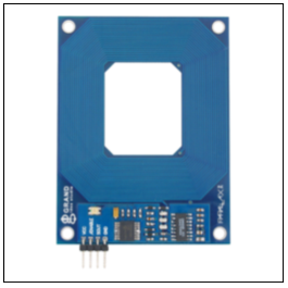
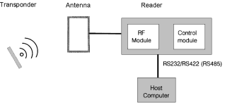
Radio frequency identification system use radio wave to transmit information between tags and readers, see Fig.3. Certain information in the tag can be identified by the reader which can be used to unlock a door. In the tag there is a coil and a micro chip, the chip will respond when the tag is close to the reader through electromagnetic field. The coil in the reader act as a power source, meanwhile it is also an antenna to receive the data transmit by the tag, see Fig.4. [1]
 Â
- (b)
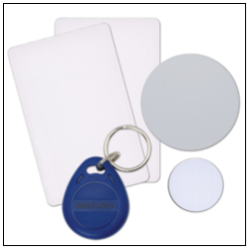
FIGURE 3:(a) RFID reader, (b) tags
1.2.1 Tags
Radio frequency identification system use tags or labels as identifications. Two-way radio transmitter-receivers as known as interrogators or readers send a signal to the tag and read its response.
There are three type of RFID tags passive, active or battery-assisted passiveï¼»9ï¼½. An active tagï¼»10ï¼½ is battery charged and its ID signal is periodically transmitted. One example of an active tag is the transponder attached to an aircraft that identifies its national origin [2]. Olivetti Research Ltd’s Active Badge, used to determine the location of people and objects in a building is an example of a small wearable active tag with a lifetime of about 1 year [11]. A battery-assisted passive (BAP) has a small on-board battery and is activated when in the range of an RFID reader. A passive tag is the cheapest and smallest among these three – there is no battery in it – the tag uses the radio energy from the electromagnetic field cause by the reader instead. However, passive tag requires a much stronger radio transmitter than for signal transmission.
Tags could be read-only or read/write. Read-only tags have a serial number wrote in from the factory that is used as a key into a database, while read/write ones can have data write by system users. Field programmable tags can be write-once, read-multiple; “blank” tags can be written with an electronic product code by the user.
Passive RFID tags contain at least three parts: a circuit, an antenna and some form of encapsulation, see Fig.5. [3]. The integrated circuit is used for storing and processing information, modulating and demodulating a radio-frequency (RF) signal, collecting DC power from the incident reader signal, and other specialized functions; and the antenna for receiving power and transmitting the signal. The RFID tag includes either fixed or programmable logic for processing the transmission and sensor data, respectively.
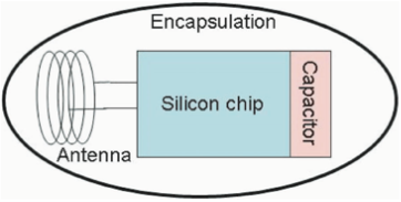
FIGURE 5:Logical components of an RFID tag. Note that the antenna can take many forms including a coil and a dipole depending on the tag type
An RFID reader send an encoded radio signal to the tag. The tag then receives the message and communicates back with its identification and other information. This may be a unique tag serial number, product-related information, a password or other specific information. Since tags have individual serial numbers, the RFID system can discriminate among several tags and read them simultaneously when they are within the range of the RFID reader.
1.2.2 Readers
Radio frequency identification system can be defined into 3 types by different tags and readers.
A Passive Reader Active Tag (PRAT) system is a combination of passive reader (only receives radio signals) and active tags (battery operated, transmit only). The operation range of a Passive Reader Active Tag system reader can be adjusted from 0-600 m. Which allows flexibility in applications such as asset protection and supervision.
An Active Reader Passive Tag (ARPT) system has an active reader, which transmits interrogator signals and also receives authentication replies from passive tags.
An Active Reader Active Tag (ARAT) system uses active tags awoken with an interrogator signal from the active reader. A variation of this system could also use a Battery-Assisted Passive (BAP) tag which acts like a passive tag but has a small battery to power the tag’s return reporting signal.
The signal intensity of readers can be set up to create a specific interrogation zone. A highly defined reading area can be created for when tags go in and out of the interrogation zone. Mobile readers may be hand-held or mounted on carts or vehicles.
1.3 A comparison between traditional KC system and RFID locking system
The keycard (KC) lock system can be a lock operated by a keycard, a flat, rectangular plastic card with identical dimensions. The card stores a physical or digital signature which can be accepted by door mechanism. There are several common types of keycards in use, including the mechanical hole card, barcode, magnetic stripe, Wiegand wire embedded cards, smart card (embedded with a read/write electronic microchip), and RFID cards. Corresponding systems operate by physically moving detainers in the locking mechanism with the insertion of the card, by shining LEDs through a pattern of holes in the card and detecting the result, by swiping or inserting a magnetic stripe card, or in the case of RFID cards, merely being brought into close proximity to a sensor. RFID locks operate differently to the traditional magnetic and chip card hotel locks, using Radio Signals in order to communicate between the guest’s Keycard and the Lock.
The older Magnetic Swipe and Chip Card systems have several drawbacks including short life cycle, impact on magnetic field, limited data storage. The older Keycard have to be inserted into the door lock. Scratches appears on the reading surface due to the physical contact between the magnetic stripe (or the Chip) and the reader. This eventually makes the cards unreadable by the lock. It will also cause failure when writing the card at the encoding station. The average life span of such a magnetic strip Key Card or chip cards is about 200 to 500 uses[3]. The older Keycard can easily be affected by small magnetic field (even interference from Mobile Phones), which makes the card unreadable and hence needing replacement. The traditional cards have a small memory capacity which makes it difficult to integrate cards with equipment like Lifts, Car Park Barriers, Vending Machines.
The RFID Locks are contactless,it operates by presenting the Key Card to the lock. The lock then reads the information stored on the card by means of RFID, and grants access to the room to valid cards. There is no physical contact between the lock and the card. With the help of RFID technology, magnetic strip or visible micro chip can be discard from the card and hence eliminates damage cause by physical contacts. This gives RFID card virtually unlimited life span. There is no need to replace or clean the reader heads. In addition the locks are free from opening slots preventing ingress of dirt, dust and other outside influences, prolonging the lifespan of the lock itself.
1.4 Limitations
Although Radio frequency identification offers the benefits of relatively low cost
compared to other wireless technology, being physically unobtrusive and enabling detailed stock tracking, it still has limitations.
The cost of tags depends on their type. In the 2003 report ‘RFID Systems in the Manufacturing Supply Chain’ [14]. Thought RFID tag can cost as little as a few cents and the cost has fallen over time, however, it still requires investment to install on a good. Comparing to the value of some goods it is not economically viable for tagging them. Especially for active tags (those that require a local power source), which can cost up to a dollar each.
Different signals from the tags may interfering with one another. A February 2011 paper for the “International Journal of Computer and Electric Engineering” notes that it isn’t easy to read multiple RFID tags simultaneously [1]. There is Computerized techniques for “detangle” such signals, but implementing and managing these techniques increases costs. [12][13]
NFC and EPC global standards are two wide-scale adoption standards for RFID, but they are fundamentally incompatible [3]. Lack of standards is an issue when two different companies attempt to share and tracking RFID information. The IJCEE paper notes that RFID does not have fixed technical standards. Cooperating partners in RFID industry need to agree in standards concerning communication protocols, signal modulation types, data transmission rates, data encoding and frames, and collision handling algorithms. [1]
There are three large regions of frequency allocations in the world — the Americas; Asia and Australasia; and Europe and Africa. The variations in wireless frequencies ranges limits companies that want to use RFID tracking for international inventory management.[1]
Intelligent Parking Assist System is a comfort function in some of the vehicles. The first system coming in the market monitored the front and rear of the vehicle and warned the driver if there is any object beside the vehicle. Ultrasonic sensors are wildly used in this technology. Together with ultrasonic sensors, video technology and some algorithms the vehicle itself is able to measure the length of a parking space and steer itself to the parking lot. Drivers must care only for the longitudinal control of his vehicle.
2.1 History and development
In 1999 Toyota Motor Corporation developed The Advanced Parking Guidance System (APGS) for Lexus models in the United States initially for the Japanese market hybrid Prius models and Lexus models. The system assists drivers in parking their cars.[15][16]Vehicles equipped with the IPAS can drive itself into a parking lot with little control from the user. The Prius Hybrid sold in Japan in 2003 installed the first version of the system.[17] In 2006, an upgraded version of the system on the Lexus LS luxury sedan[18] featured the automatic parking technology among other brand new inventions from Toyota. In 2009, the third generation Prius sold in the U.S has this feature. In Asia and Europe, the automatic parking technology is labelled as the IPAS for both Lexus and Toyota models, while in the U.S. the “Advanced Parking Guidance System” is only used for Lexus cars.
Intelligent Parking Assist System initially was designed for reverse parallel parking.[17] The system estimated the location of the parking lot and steered the vehicle without Driver’s intervention. Onboard computer used a camera and sensors built into the forward and rear of the car to detected the proximity of nearby vehicles. The dashboard showed an real-time image of the lot with a box, and the driver have to determine the exact final position of the vehicle in the lot by using arrows appeared on the screen. When satisfied, the user pressed the “Set” button, which will activated the IPAS. The system then took over steering control to maneuver the vehicle.[19]
Early versions of this system can’t detect objects properly, including cats, baby prams and pedestrians. Secondly when the driver used IPAS in a small space, the system continuously warning the user of the danger of hitting the object. User assistance is required in such situations. In 2005, recognition capability is added to the system for parking stripes.[19] A later version of this parking technology integrated the system with parking sensors in 2006.[19] This version calculated the steering movements needed for parallel or reverse parking, and help determine weather the car has enough clearance for a particular space with colored screen display.
2.2 Function
Intelligent parking assist system is widely used in some of the Toyota, Lexus cars, even world’s top sport car McLaren P1 has IPAS. Following information is the instruction of IPAS in “Toyota Prius Owners Manual”.[20]
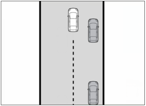
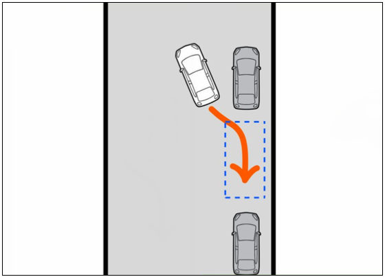
Step 1: Drive your Toyota Prius up until you see the spot you’d like to park in.
It may be behind you or in front of you (unlike those of the Ford models, where the only thing you can do with their system is parallel park the car using it’s system).(Fig.6)
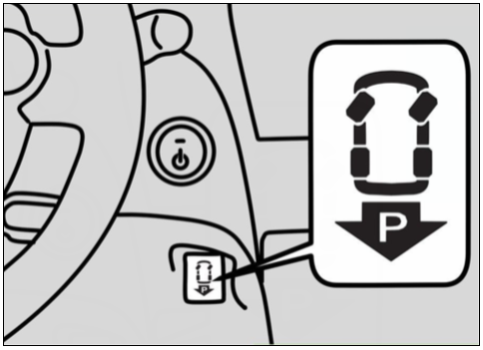
Step 2: Press the ‘ParkAssist’ button near the driver’s side of the dashboard. (Fig.7)
Step 3: Make sure that the back end of your vehicle is further forward than the spot your vehicle has been designated to be parked in.(Fig.8)
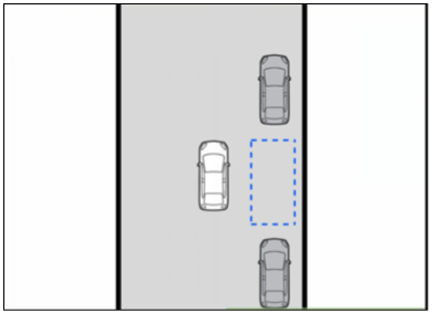
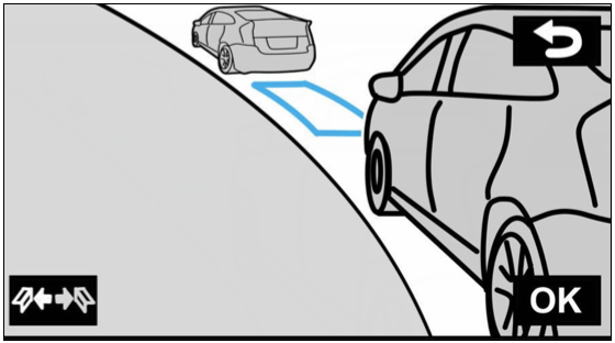
Step 4: Look at your screen up on the dashboard. The vehicle will light up spots that it thinks there is a viable enough parking space located in. Not only will it light up the screen, but it will beep to alert you that there is a parking spot nearby that it can choose.
Look for spots that turn into blue square areas. The vehicle can already determine that these spots are big enough and well suited enough to park the car there. (Fig.9)
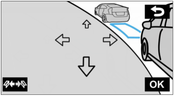
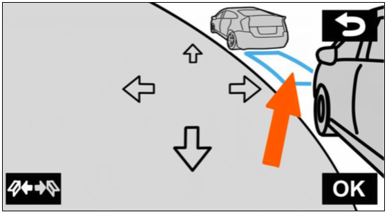
Step 5: Touch to fine-tune the parking space you believe would be a working space to park in. Use the arrow points on the screen to fine-tune the spot. Look for the “car to find out what area you may be indicating as you move around the parking lot. The arrows will “select” the spot, and will highlight the spots. (Fig.10)
Step 6: Adjust the parking space it’s designated.(Fig.11)
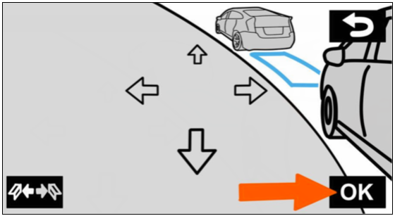
Step 7: Touch the OK button in the bottom right corner of the dashboard screen.(Fig.12)
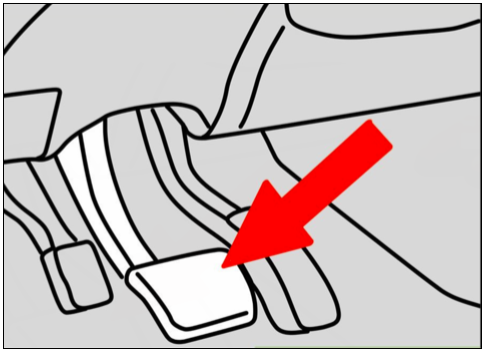
Step 8: Put your car in Reverse gear and only keep your foot on the brake pedal. Operate only the brake pedal, as you park the car. (Fig.13)
Step 9:Put your foot on the brake pedal, when you’ve backed up far enough without running through the building or into any designated non-parking areas.(Fig.14)
Step 10: Cancel the guidance feature on your vehicle by pressing the X button on the display. (Fig.15)
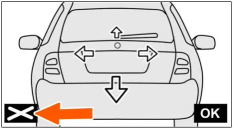
FIGURE 15: IPAS instruction 10
2.3 Principle of IPAS technology
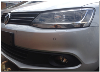
The IPAS use computer to process signals from the vehicle’s sonar warning system, backup camera and two additional forward sensors on the front side fenders(Fig.16). The sonar park sensors including multiple sensors on the forward and rear bumpers which detect objects, allowing the vehicle to calculate optimum steering angles during regular parking. [19] The Intelligent Parking Assist System expands on the function of these sensors and is accessible when the vehicle is shifted to reverse (which automatically activates the backup camera). The central processor calculates the best parallel or reverse park steering angles and then implement with the Electric Power Steering systems of the vehicle to guide the car into the parking spot.
2.4 Sensor technologies in Intelligent parking assist system
2.4.1 Ultrasonic sensor
In the past 20 years, Ultrasonic sensors are used for many applications for military application in submarines, in Medicine for diagnostics, and as sensors for distance measurement in industry. Automotive applications use piezoelectric ultrasonic transducers since 1993 as they are small and robust.(Fig.17)
The piezoelectric effect describes electromechanical property of a crystal. a mechanical deformation appears when a piezoelectric crystal is applied an electric field on its two sides. A mechanical deformation of the crystal can also generate an electric voltage measured at the crystal’s electrodes. The voltage is proportional to the deformation. Thus piezoelectric materials can be used as high frequency (ultrasonic) oscillation generators and sound wave receiver. An ultrasonic piezoelectric element can be considered as a loudspeaker and a microphone in one unit, therefore it is known as transducers. [21]
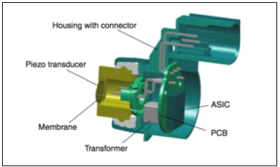
FIGURE 17: the cross section of the car ultrasonic sensor
2.4.2 Video technology
2.4.2.1 CCD and CMOS technology
CCD and CMOS are wildly used as image sensors. In a charge-coupled device (CCD), electrical charge move within the device to an area where the charge can be manipulated. Linear array of MOS capacitances are combined so that a stored photo charge can be moved. Photo charge pairs are generated in the semiconductor under the influence of incident light. Interline-transfer CCDs are the mostly used type in automobile applications. (Fig.18) The charges are sequentially and vertically transferred to a register. [22]
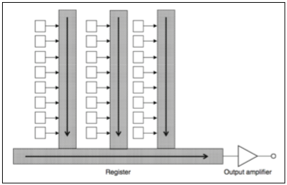
FIGURE 18: Interline-transfer CCD [21]
CMOS sensors use non-integrating photodiodes which are independent from the exposure time. It has a characteristic similar to the human eye which means CMOS has a high dynamic range.
CMOS sensors have more advantages than the more generally used CCDs: they have lower costs by taking advantage of submicron CMOS technology. Several functionalities can be integrated on the sensor itself. The power consumption is low as the circuitry in each pixel only activated during the readout period, there is no clock signal driving large capacitance as well. Readout speed can be enhanced by parallel access to multiple taps of the pixel array. As a result, CMOS sensors are favored using on automotive.
2.4.2.2 Video Cameras and Vision System
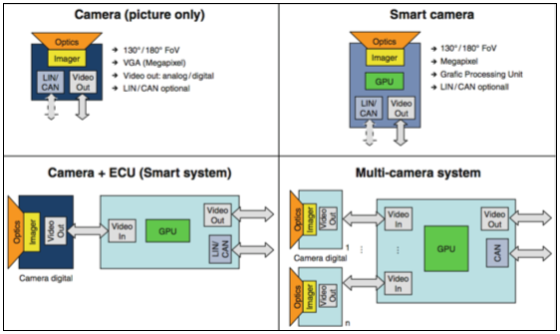
FIGURE 19: structures and camera system structures of Parking and maneuver assistance systems
There are four structures of video cameras, see Fig.19. The camera for photo only has a standard NTSC- format of its video data. Meanwhile, digital cameras with a LVDS interface are mostly used. The camera parameters can be controlled by an external CPU with the optional LIN/CAN interface.
With the help of internal Graphic Processing Unit (GPU), smart cameras can extract features from the picture and thus provide additional information to the device. Due to the space and thermal conditions, these cameras are limited in its functionality.
They are a combination of a digital camera with an external GPU called smart system in which two components can be connected via LVDS. An multi-camera system typically has more cameras in used.
2.5 Limitations on Parking Assistance Systems
Ultrasonic technology has some limitations in functionality as follow. Sound absorbing materials are hardly seen by the system. The system has a short detection range for people who wears absorbing cloths. The system will be influenced by objects in the vicinity of the own vehicle, in particular the noise of compressed air like truck brakes. The detection range may differ by mud or snow covered on it under severe weather conditions.[23]
Video technology has also restrictions: visibility range of cameras may reduced by poor weather conditions (Silicon sensor technology will have a significant impact). Like the ultrasonic sensor, camera lenses may be covered with mud or snow at poor weather conditions and must be cleaned frequently. Due to their limited performance, Parking systems based on ultrasonic sensors and cameras are therefore defined as comfort systems.[23]
Ultrasonic sensors and video cameras are excellent supplement to each other for their different physical principles. Each technology has individual strengths supporting the weaknesses of the other. The camera-based system can be improved by being combined with an ultrasonic system with the ability to measure the distance to objects. This allows the detection of objects while visual quality is poor for the camera system. The video picture together with an ultrasonic parking system contains much more information for the driver. This is an important step towards more detection security and functional safety.[23]
Radar sensors with a longer detection range can be mounted behind the bumper of the vehicle. They may be used for IPAS as well as for safety functions like collision avoidance or collision mitigation. [23]
Radio frequency identification (RFID) and Intelligent parking assist system (IPAS) are wildly used in our daily life. This report discussed RFID in the field of electrical lock system and IPAS in car industry.
The first RFID device was developed to be a mobile toll system, and the similar technology was invented to be an espionage tool back in 1945. Radio frequency identification use radio wave as a medium in communication between reader and tag. An RFID tag can be either passive or active. A passive tag is powered by electromagnetic field generated by the reader, while an active tag has its own battery. The reader send signal to interrogate the tag, the tag will respond when it is in the range of the reader. The data in the tag can be used as a key to unlock doors so that RFID lock system are generally used in hotels. Since the RFID has its contactless characteristic, RFID locker is better than traditional keycard mechanism. Locks with RFID technology have a longer life cycle and low maintain expense. However, it still has some drawbacks in cost, signal interference, frequency, standard.
IPAS was first developed on Lexus models, the technology integrated ultrasonic sensor, camera system, electrical steering system and on board computer. The vehicle will drive itself to the parking lot without the driver’s assist. The two main components – ultrasonic sensor and camera supporting the weaknesses of the other. The ultrasonic sensors are used to detect surrounding objects while the camera is used to locate the parking area. The system has its limitations in signal interference, natural factors.
References
[1] Mandeep Kaur, Manjeet Sandhu, Neeraj Mohan and Parvinder S. Sandhu, “RFID Technology Principles, Advantages, Limitations & Its Applications”, International Journal of Computer and Electrical Engineering, Dec. 2011.
[2] K. Finkelzeller, The RFID Handbook, 2nd ed., John Wiley & Sons, 2003.
[3] Roy. Want, “RFID Explained: A Primer on Radio Frequency Identification Technologies”, Morgan & Claypool, 2006.
[4] Stockman, Harry (October 1948), “Communication by Means of Reflected Power”, Proceedings of the IRE, 36 (10): 1196-1204.
[5] “Real Time Location Systems” (PDF). clarinox. Retrieved 2010-08-04.
[6] Charles A. Walton “Portable radio frequency emitting identifier” U.S. Patent 4,384,288 issue date May 17, 1983
[7] Hacking Exposed Linux: Linux Security Secrets & Solutions (third ed.). McGraw-Hill Osborne Media. 2008. p. 298. ISBN
[8] “Genesis of the Versatile RFID Tag”. RFID Journal. Retrieved 2013-09-22.
[9] R. Want and D. Russell, “Ubiquitous electronic tagging,” IEEE DS-Online.
[10] D. J. Moore, R. Want, et al., “Implementing phicons: Combining computer vision with infrared technology for interactive physical icons,” in Proc. ACM UIST’99, Ashville, NC, pp. 67-68, Nov. 8-10, 1999.
[11] R. Want, A. Hopper, V. Falcao, and J. Gibbons, “The active bad
Cite This Work
To export a reference to this article please select a referencing stye below:
Related Services
View all


DMCA / Removal Request
If you are the original writer of this essay and no longer wish to have your work published on UKEssays.com then please click the following link to email our support team:
Request essay removal