Radial Ball Bearing Material
| ✅ Paper Type: Free Essay | ✅ Subject: Engineering |
| ✅ Wordcount: 2239 words | ✅ Published: 31 Aug 2017 |
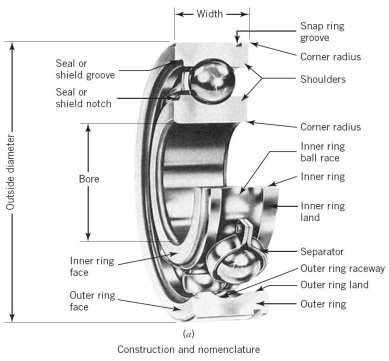
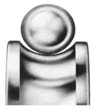
You are tasked with selecting a material that is suitable for the balls in a radial ball bearing such as the one shown in Fig. 1. Radial ball bearings although intended primarily for radial loads, will also carry a certain amount of thrust.
Ball
The following details are known in relation to radial ball bearing design:
- Young’s modulus should have a minimum of 200 GPa.
- The compressive strength should have a value  300 MPa.
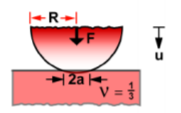
- The balls must not fail under load. It can be assumed that the contact stress can be modelled for a sphere on a flat (see Fig. 1). An assumption should be made that the material for the ball and the raceway are the same and therefore they have the same moduli and Poisson’s ratio has a value of 1/3.
- The balls should be light.
Material selection process. This refers to selecting a material that meets all the constraints and objective below.
Design requirements:
Table 1 Table of design requirements
|
Function |
Suitable for balls in a radial ball bearing |
|
Constraints |
|
|
Objectives |
|
|
Free variables |
|
 ).
).Below is a figure of all materials with a mechanical property (Young’s modulus greater than 200Gpa and Compressive strength greater than 300Mps) against density:
Seen below is a table of the materials and their corresponding Young’s modulus.
|
Name |
Young’s modulus (GPa) |
|
Tungsten carbides |
625 – 700 |
|
Boron carbide |
440 – 472 |
|
Silicon carbide |
400 – 460 |
|
Alumina |
343 – 390 |
|
Tungsten alloys |
310 – 380 |
|
Aluminium nitride |
302 – 348 |
|
Silicon nitride |
290 – 318 |
|
Zirconia |
200 – 250 |
|
Nickel-based super alloys |
150 – 245 |
|
Nickel-chromium alloys |
200 – 220 |
|
Nickel |
190 – 220 |
|
Low alloy steel |
205 – 217 |
|
Medium carbon steel |
200 – 216 |
|
Low carbon steel |
200 – 215 |
|
High carbon steel |
200 – 215 |
|
Stainless steel |
|
Although seen above, 16 values have passed the requirements so far, further analysis will be conducted, and this can be seen below;
The below table illustrates the materials that meet the design requirements, the table is ranked based on Young’s modulus, from highest modulus to lowest. The Compressive strength of the material must also be considered, a minimum compressive strength of 300MPa must apply.
The table below illustrates each materials Young’s modulus and corresponding compressive strength.
Table 3 Materials with Young’s modulus and compressive strengths that meet design requirements (density also noted)
|
Name |
Young’s modulus (GPa) |
Compressive strength (MPa) |
|
Tungsten carbides |
625 – 700 |
3.35e3 – 6.83e3 |
|
Boron carbide |
440 – 472 |
2.58e3 – 5.69e3 |
|
Silicon carbide |
400 – 460 |
690 – 5.5e3 |
|
Alumina |
343 – 390 |
690 – 5.5e3 |
|
Tungsten alloys |
310 – 380 |
555 – 800 |
|
Aluminium nitride |
302 – 348 |
1.97e3 – 2.5e3 |
|
Silicon nitride |
290 – 318 |
524 – 5.5e3 |
|
Zirconia |
200 – 250 |
3.6e3 – 5.2e3 |
|
Nickel-based super alloys |
150 – 245 |
300 – 1.9e3 |
|
Nickel-chromium alloys |
200 – 220 |
365 – 460 |
|
Nickel |
190 – 220 |
70 – 1e3 |
|
Low alloy steel |
205 – 217 |
400 – 1.5e3 |
|
Medium carbon steel |
200 – 216 |
305 – 1.76e3 |
|
Low carbon steel |
200 – 215 |
250 – 395 |
|
High carbon steel |
200 – 215 |
335 – 1.16e3 |
|
Stainless steel |
189 – 210 |
170 – 1e3 |
Below is a bubble chart of Young’s modulus versus compressive strength:
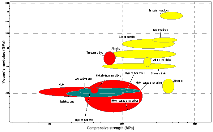
Figure 2 Bubble chart of Young’s modulus of Compressive strength
The above figure is on a logarithmic scale. Only materials that have passed the requirements were plotted.
When surfaces are placed in contact they touch at one or a few discrete points. If the surfaces are loaded, the contacts flatten elastically and the contact areas grow until failure of some sort occurs. (Duffy, 2010) Compressive stress causes this. As the requirements state; should be modelled as a sphere on a flat, this allows the student to use following formulae (contact stresses);
(Duffy, 2010)
(Yield Stress) 
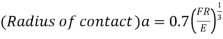
The following is subbed in to produce the below:
 x
x 
 x
x 
 x
x 
 x
x 
= 
= 
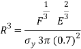
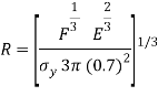
The mass of the sphere must be derived, this is done below;
 Where
Where  is density and
  is volume
Volume of a sphere is denoted as: 

m= 

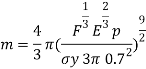
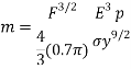

The student knows the objective is to minimise the mass of the ball, the derivation above is done on that basis and results in the equation being flipped above.
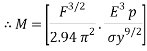
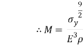
From the material selection index above, the equation can be related in the logarithmic scale:

 =
= 

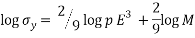
This results in: 
This now means the slope can be known to be  = 0.222
The above value is known as an index line;
Index lines can be used to compare the performance of different materials, and to find replacement materials. Materials that are on the line will all perform equally well in each design. Materials above the line have a higher performance index and will therefore perform better; those below the line have a lower index value. (Edupack, 2006)
The below bubble chart illustrates the material selection process using the slope;
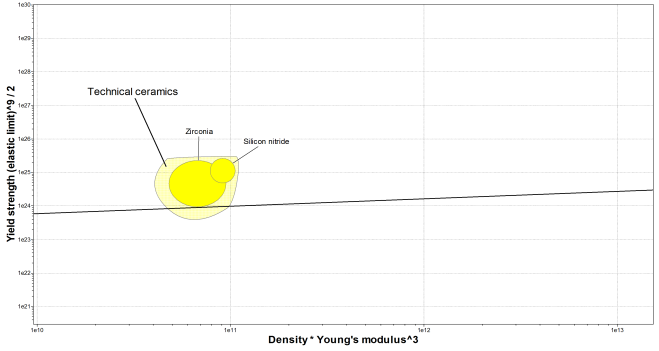
Figure 4 Material selection with material index
As seen from above, with a material index of 0.222 the following two materials passed (whole record is within the selection was used);
|
Name |
Index slope =0.2222 |
|
Silicon nitride |
6.55e101 |
|
Zirconia |
1.66e100 |
As seen from above the materials are both ceramic.
An additional chart plotting the materials costs can also be seen below;
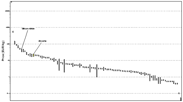
Figure 5 Price of selected material
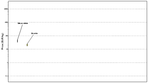
Figure 6 Price of selected material Pass only
A table of the materials cost can also be seen below;
|
Name |
Price(EUR/kg) |
|
Zirconia |
17.1-24.7 |
|
Silicon nitride |
32.3-49.4 |
(i)
It has been identified that both Young’s modulus and compressive strength are important material properties when selectin ball bearings, below is a detailed summary of why each property is important;
- Young’s modulus refers to a materials elastic modulus. This determines the stiffness of a solid material. This is a proportional (constant) between stress as long as stress is less than the yield point. This results in a smaller strain with the same stress in a stiffer material. In relation to a ball bearing Young’s modulus of Silicon nitride is about 1.5 times that of steel, meaning a smaller contact surface is present when there is a high contact pressure. Hertz theory means the maximum load for combination steel- Silicon nitride reduced with 30%.
In relation to the contact of the bearing we know it will be a sphere on a flat. The balls within a bearing are going to experience both an axial and radial force. If the force is too great for the material this may result in deformation (changing of shape). This affects the ball bearings ability to perform, this can be compared to as a wheel on a car, if it is flat may result in a pulling motion. If severe deformation occurred this may result in the bearing not allowing for rotation. This means that Young’s modulus is important when selecting materials for ball bearings.
Young’s modulus mathematical representation; 
It is noted from CES EduPack that silicon nitride is used mostly for ball bearings the Young’s modulus is known to be; 290-318 GPa (Edupack, 2006)
- Compressive strength refers to a materials resistance to compressive stress. This is when a force is applied in an inwards direction in the material. It is opposite to tensile stress. As a ball bearing is going to have one point of contact, (below) compressive strength is an important element in choosing the material. This is due to the radial forces applied when the ball is in the raceway. Once again, if the radial force is greater than the materials compressive strength abilities this will result in deformation. This will affect the bearings performance. Compressive strength can be up to 10 times greater than tensile stress. Ceramic material has a good compressive strength due to crack propagation, since there are more internal cracks in ceramics (than most materials) if placed under tension cracks will propagate and produce failure where if it is placed under compression it works in the opposite manner.
Compressive strength mathematical representation; 
It is noted from CES EduPack that silicon nitride is used mostly for ball bearings the compressive strength is known to be; 524-5.5e3 MPa (Edupack, 2006)
(ii)
The other material properties of Silicon Nitride which lead to superior operating performance can be seen below;
General properties
Density3.1e3-3.4e3kg/m^3
Price*32.3-49.4EUR/kg
Date first used1958
Mechanical properties
Young’s modulus290-318GPa
Shear modulus*100-128GPa
Bulk modulus*210-232GPa
Poisson’s ratio0.26-0.28
Yield strength (elastic limit)*600-720MPa
Tensile strength600-720MPa
Compressive strength524-5.5e3MPa
Elongation0% strain
Hardness – Vickers1.4e3-1.6e3HV
Fatigue strength at 10^7 cycles*300-500MPa
Fracture toughness4-6. 7MPa.m^0.5
Mechanical loss coefficient (tan delta)*2e-5-5e-5
Thermal properties
Melting point2.39e3-2.5e3°C
Maximum service temperature1e3-1.2e3°C
Minimum service temperature-272–271°C
Thermal conductor or insulator?Good conductor
Thermal conductivity22-30W/m.°C
Specific heat capacity670-800J/kg.°C
Thermal expansion coefficient3.2-3.6µstrain/°C
Electrical properties
Electrical conductor or insulator?Good insulator
Electrical resistivity1e20-1e21µohm.cm
Dielectric constant (relative permittivity)7.9-8.1
Dissipation factor (dielectric loss tangent)*5e-4-7e-4
Dielectric strength (dielectric breakdown)*11-131000000 V/m
Optical properties
TransparencyTranslucent
Refractive index1.95-2
Processability
Moldability2-3
Weldability1-2
Eco properties
Embodied energy, primary production116-128MJ/kg
CO2 footprint, primary production4.63-5.12kg/kg
RecycleRecycle
(Edupack, 2006)
The above characteristics result ceramic materials being the optimum material for ball bearings;
High speed, faster acceleration this is because ceramics are only 40% as dense as steel. However, the material can deliver 30-50% higher running speeds with reduced skidding and less lubrication needed.
Lighter in weight ceramic ball bearings are more rigid to that of steel ball bearings and lighter in weight. This allows for lower coefficients and a higher overall RPM (rotation per minute)
Greater accuracy since ceramics has 50% higher modulus of elasticity than steel. This means less of a deformation which leads to vibration and spindle deflection, this increases components productivity and quality.
Reduced friction: benefits of this include: longer life, energy efficiency reduced noise levels, less heat and less lubrication needed.
Non-conductive materials like Silicon nitride eliminate the pitting and fluting of raceways which ic common in electrical motor applications. If steel is used in bearings the electricity could cause magnetic field (EMF) and this could act as a conducted damaging the bearings over time. Ceramic materials are immune to EMF, which mean they perform well even when electricity is present.
Corrosion resistance – Silicon nitride; more effective than steel balls in the presence of liquids such as water or corrosive materials. Corrosion resistance can be enhanced when ceramic balls are used with dry fil, lubricant on the ring and retainer components.
Longer operating life Up to 5 to 10 times longer than standard metal bearings.
Higher temperature operation ceramic ball bearings can operate in high temperatures (up to 1,800 °F)
Less noise and vibration due to a lower coefficient of friction
(Ibsco, 2011)
The two materials chose were Silicon Nitride and Zirconia. A brief description can be seen below outlining why the individual ceramic is the optimum choice;
Silicon Nitride:
This material contains high temperature capabilities, meaning it has a low thermal expansion coefficient which gives good thermal shock resistance compared to other ceramic materials. The material is up to 58% lighter than steel silicon (Carter, 2009). As the material is lighter it means a smaller force is needed to roll the element. The main advantage to this is that silicon nitride can carry similar loads to that of silicon steel with less force needed.
Zirconia:
Zirconia was made for high performance duties such as (atmospheric journeys). This means the material has the highest temperature ability. However, this material has a high thermal expansion (almost like steel) but weighs less so it does not have the same weight saving and thermal shock resistance found in other ceramic materials. (Carter, 2009)
Zirconia is used when low loads are applied or when high temperature capabilities are needed (corrosive too).
(iii)
Porosity refers to a measure of void (empty spaces in a material) and is a fraction of the volume of voids over the total volume between 0% and 100% (Quora, 2003)
Technical ceramics do not have open porosity. To achieve porosity manufacturing process must be done (use of additives). This then allows closed and open pores to be created, ranging from nm to µm.
Porosity can have various effects on the mechanical properties of ceramics (as chosen). The following properties are effected:
- Compressive strength
- Density
- Fatigue
- Young’s modulus
- Fracture toughness
- Shear modulus
- Tensile strength
Any residual porosity will influence elastic properties and strength. For some materials, the magnitude of the modulus of elasticity E decreases with volume fraction  per;
per;
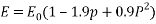
It is known that porosity affects flexural strength as it reduces cross-sectional area. It also results in pores acting as stress concentrates. (Duffy, 2010)
(iv)
Below is a completed table for ceramic materials having 20vol% porosity. This is done by using the following;
The below calculation for silicon nitride is done for clarity;
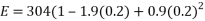 )
)
= 199.424 GPa
Where  is the modulus of elasticity and is the porosity volume.
Table 5 Ceramic materials with 20vol%
|
Material |
Modulus of Elasticity GPa |
Porosity at 20vol% |
E(20%) Porosity GPa |
|
Silicon nitirde |
304 |
0.2 |
199.424 |
|
Zirconia |
205 |
0.2 |
134.48 |
|
Silicon carbide |
345 |
0.2 |
226.32 |
|
Aluminum oxide |
393 |
0.2 |
257.808 |
|
Glass-ceramic |
120 |
0.2 |
78.72 |
|
Mullite |
145 |
0.2 |
95.12 |
|
Spinel |
260 |
0.2 |
170.56 |
|
Magnesium oxide |
225 |
0.2 |
147.6 |
|
Fused silica |
73 |
0.2 |
47.888 |
|
Soda-lime glass |
69 |
0.2 |
45.264 |
As seen from the above, silicon nitride is the ceramic material resulting in a modulus of elasticity when having a porosity volume of 20%.
References
Carter, 2009. Carter. [Online]
Available at: http://www.carterbearings.co.uk/unasis/hybrid-and-ceramic-bearings/ceramic-matericals-and-their-properties-part-2/
[Accessed Saturday Feburary 2017].
Duffy, J., 2010. Moodle. [Online]
Available at: http://moodle.itb.ie/pluginfile.php/115304/mod_resource/content/0/CES%20EduPack%20-%20USEFUL%20SOLUTIONS%20to%20COMMON%20PROBLEMS%202008%20-%2001Jan13.pdf
[Accessed Wednesday Feburary 2017].
Edupack, C., 2006. s.l.: s.n.
Ibsco, 2011. Ibsco. [Online]
Available at: http://www.ibsco.com/ceramic-ball-bearings.php
[Accessed Saturday Feburary 2017].
Quora, 2003. Quora. [Online]
Available at: 2017
[Accessed Wednesday Feburary 2017].
Cite This Work
To export a reference to this article please select a referencing stye below:
Related Services
View all


DMCA / Removal Request
If you are the original writer of this essay and no longer wish to have your work published on UKEssays.com then please click the following link to email our support team:
Request essay removal