Progame and Design of Basketball Timer
| ✅ Paper Type: Free Essay | ✅ Subject: Engineering |
| ✅ Wordcount: 1437 words | ✅ Published: 18 May 2020 |
Abstract
The utilization of pins in a programmable integrated circuit were achieved through efficient coding and design. The number of pins required for Interfacing multiple seven segment display were minimized by integrating the concept of multiplexing, Timer0 module, and implantation of binary coded decimal to seven segment display decoder integrated circuit. Together, these concepts had led to the implementation of a timer application namely the basketball game clock and shot clock. The project is implemented using MPLAB X IDE and Proteus Simulation. Further, the circuit is developed using breadboard. This type of project is one practical step towards integrating timer concept to vast real time embedded applications.
Introduction
In today’s time, the advancement of technology made people’s lives easier. One of the key contributors to this is the invention of devices that helps people in doing their task. Furthermore, most of these devices have microcontrollers that is designed based on their features. Due to the countless applications of microcontrollers, learning how to program and design them will lead to a better understanding on how each device perform their functions and possibly create new innovations.
Firstly, microcontrollers offer different types of module depending on their family. Among those modules, timer is considered as the most integrated concept and most of present microcontrollers have this feature built into them. There are several applications of timer module that a typical human being benefits from in their daily life such as clock, microwave oven, and even in traffic lights. That is why understanding the fundamentals of timer module and learning how to use it in microcontrollers are essential.
Further, it is also important to understand the interfacing of devices in microcontrollers in order to perform its intended operation. One of the main types of interfacing is I/O interfacing which enables the transferring of data between microcontrollers and different peripherals such as sensors, keypads, and displays.
Overall, understanding these concepts is only possible when it is carried out in an actual application. That is why to showcase the different features of microcontrollers, a prototype of basketball scoreboard with game clock and shot clock will be implemented.
Background/Related Works
Basketball Scoreboard
A basketball scoreboard provides a visual presentation for the viewers of the games where each team’s scores as well as the time left for each quarter or half period are displayed.

Figure 1. Basketball Scoreboard [1].
Figure 1 illustrates a typical scoreboard of a basketball game wherein several 7-segment displays were used to show the scores of home and guest team and the game clock.
Basketball Shot Clock
A shot clock shows the amount of time required for players to shoot the ball for each possession. Most of basketball games use a twenty-four second shot clock. When the ball hits the rim, the clock resets either back to twenty-four seconds or fourteen seconds depending on which team will get the next possession.

Figure 2. Basketball Shot Clock [2].
Figure 2 shows a typical shot clock located at the top of a ring in an ongoing basketball game wherein the time is presented using dot matrix. However, in the implementation of the project, 7-segment displays will be used.
Proposed Project – Working Principle
Voltage Regulator
Using a voltage regulator is one of the important concepts in electronics due to the sensitivity of most electronic components. Basically, a voltage regulator provides a fixed voltage output irrespective of varying loads or input voltage [3].

Figure 3. Schematic Diagram of Voltage Regulation [3].
Figure 3 shows the schematic diagram for regulating the voltage composed of the voltage regulator and two capacitors. For the project, the input will come from a 9V battery power source. Meanwhile, the output will provide the required 5V for the programmable integrated circuit.
Multiplexing
One way to interface multiple seven segment displays effectively is through multiplexing. Basically, multiplexing is a concept of combining multiple signals into a single signal which will be transmitted through a medium [4].

Figure 4. Schematic Diagram of Multiplexed Four Digit Seven Segment Display [5].
Figure 4 shows the schematic diagram of multiplexed seven segment display with resistors and NPN transistors. The transistors and resistors will drive the seven-segment display based on its required current ratings.
Digital Display Decoder
In order to manipulate the information to display in a seven-segment display easily, use of digital display decoder is one of the most efficient way. The most common type of digital display decoder is the Binary Coded Decimal (BCD) to seven-segment display decoder. The function of this decoder is to provide an easy way of translating binary patterns of seven-segment display by just using four data bits [6].

Figure 5. Binary Pattern for BCD Display Decoder [6].
Figure 5 shows the binary patterns of numbers for a BCD display decoder. It is important to take note that this decoder only accepts a valid input of numbers from 0 to 9. Hence, the binary patterns of A to F for a seven-segment display will not be translated by this type of decoder.

Figure 6. Example of BCD to Seven Segment Display Decoder [6].
Figure 6 shows an example of how a display decoder works. Based on the 0100 binary pattern of switches in the input, the number “4” is shown in the seven-segment display.
Timer0 Module
Any 8-bit PIC MCU families has Timer0 module built on them. This module offers different features such as timer/counter register, programmable internal or external clock source, interrupt on overflow, and etc [7].

Figure 7. Block Diagram of Timer0 Module [7].
Figure 7 shows the simplified block diagram of a Timer0 module wherein during timer mode, instructions is incremented by each clock pulse. However, the speed of increment may be changed by modifying the prescaler.
Project Design

Figure 8. Proteus Simulation of the Basketball Timer.
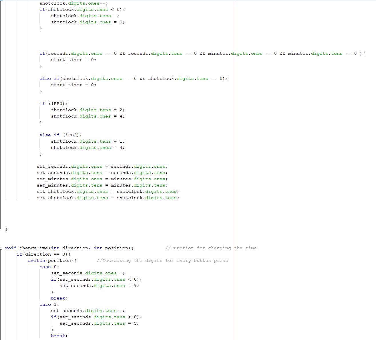
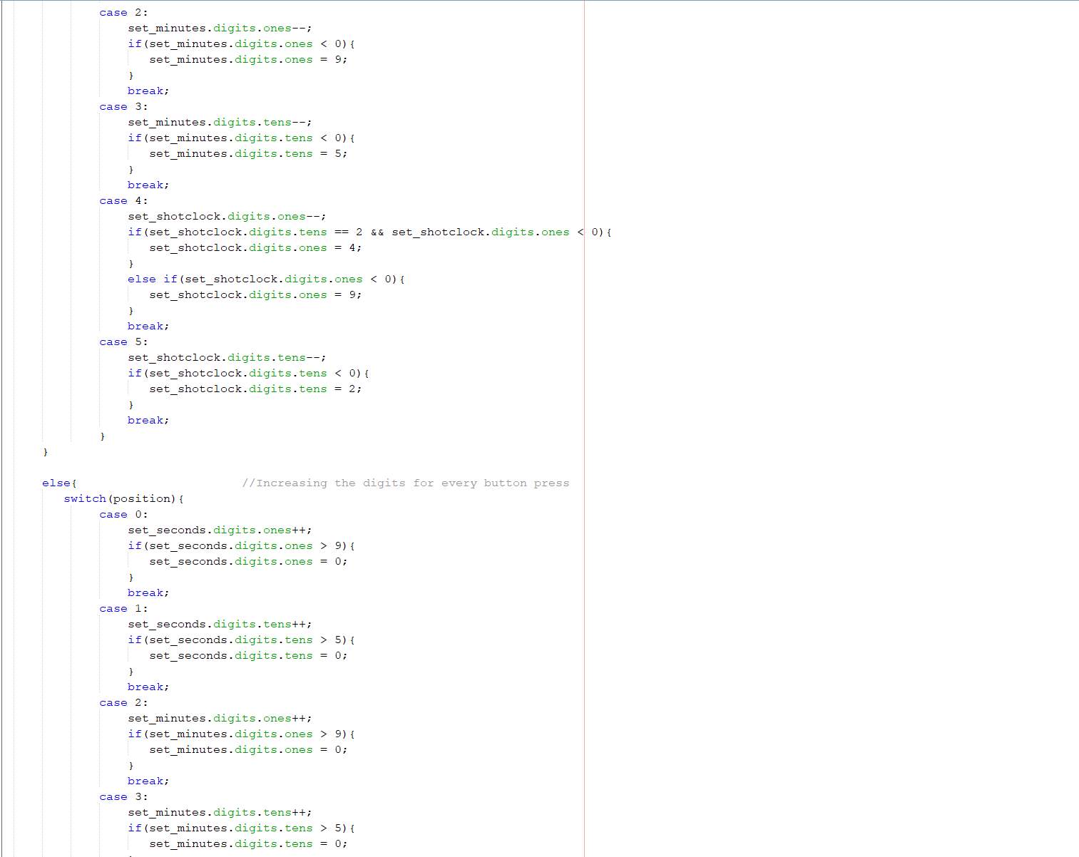
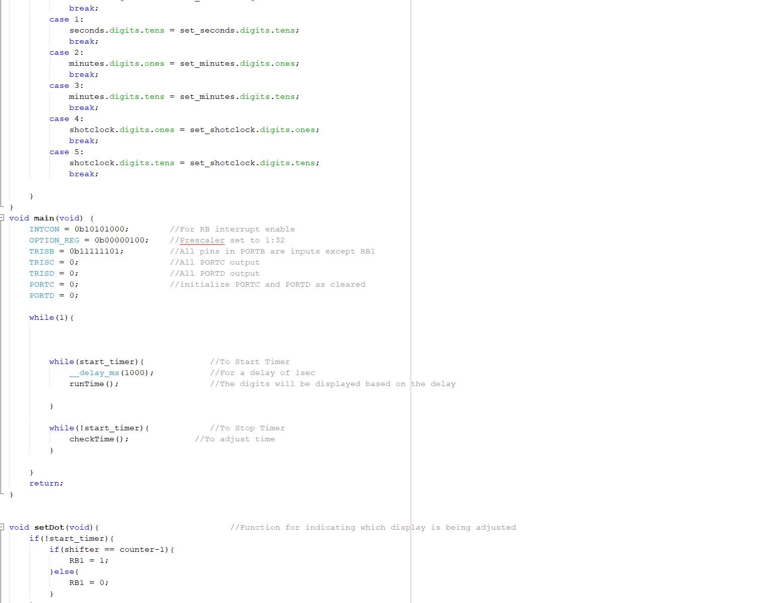
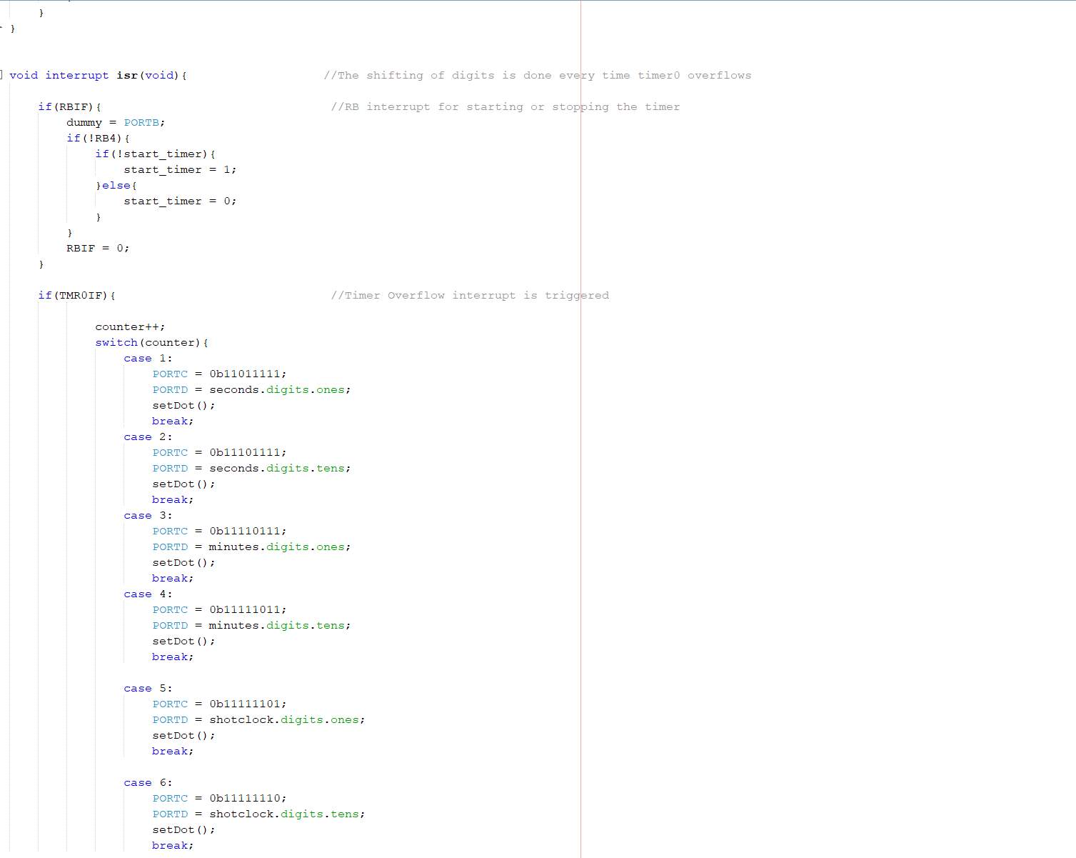
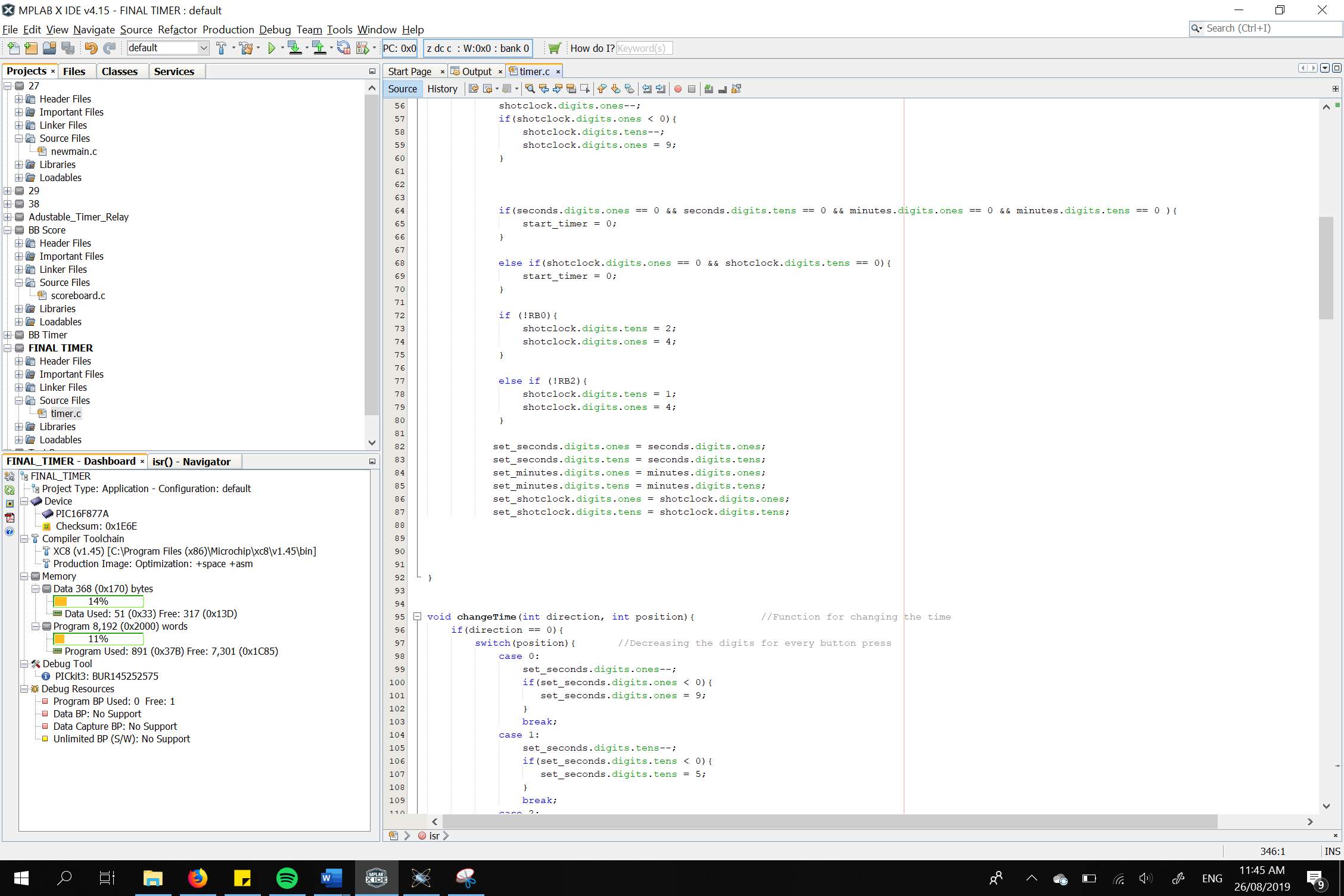
Project Code


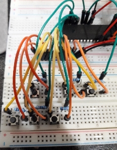
Project Implementation
- PIC16F877a
- 74LS48 BCD to Seven Segment Decoder IC
- 7805 5V Voltage Regulator IC
- NPN Transistors
- 4 MHz Crystal Oscillator
- 9V Battery
- Capacitors
- Resistors
- Breadboard
- Jump Wires
Methods
- Developing the Codes in MPLAB X IDE
- Simulation in Proteus

- Interfacing Voltage Regulator

- Interfacing Crystal Oscillator

- Interfacing Seven Segment to Display Decoder

- Interfacing Seven Segment and Display Decoder to PIC16F877a

- Interfacing Push Button Controls to PIC16F877a
- Overall Connection

Challenges in Implementation
The group faced several challenges during the implementation of the project. Firstly, during the coding of the program, there are several factors that needed to be considered in order to utilize the number of pins of the programmable integrated circuit. For instance, Timer 0 module must be developed in the program to be able to implement the multiplexing of seven segment display. In addition, to minimize the number of lines of codes as much as possible, the use of BCD to Seven Segment Display Decoder IC was considered.
Secondly, the interfacing of peripherals due to the number of electronic components needed to be connected. For example, the use of multiple push buttons alone would require several jumper wires due to its connection to the ground, power source, and to the programmable integrated circuit.
Lastly, the debugging of the programmable integrated circuit. Due to challenges that were faced in using the PICKIT3 and Demo Board, the implementation of a working prototype was accomplished using breadboard.
Limitations of the Project
The project is limited only to provide a game clock timer of minutes and seconds. Hence, games lasting for more than an hour is not applicable. Also, the shot clock timer is only limited to up to twenty-four seconds with a reset of either twenty-four or fourteen seconds only. Further, even though when the game clock is less than twenty-four seconds, the shot clock still operates.
Conclusion
In conclusion, due to the vast applications of microcontrollers in different technologies, knowledge in designing and implementing microcontrollers must be developed. One way of doing these is through implementation of projects. However, it is important to take note that there are multiple ways of implementing a specific application. Thus, utilization of resources in developing an application can be achieved through efficient design and coding.
References
|
[1] |
“Basketball Scoreboard from Daktronics,” 1stdibs, 2019. [Online]. Available: https://a.1stdibscdn.com/archivesE/upload/f_9235/f_70145731490574763142/DSC_3113_master.JPG. [Accessed 07 August 2019]. |
|
[2] |
B. Vasallo, “Shot Clock and 14 second reset.,” Malta Basketball Association, 7 January 2018. [Online]. Available: http://mba.org.mt/shot-clock-and-14-second-reset/. [Accessed 07 August 2019]. |
|
[3] |
“Electronics Fundamentals: Voltage Regulator,” Jameco Electronics, [Online]. Available: https://www.jameco.com/Jameco/workshop/learning-center/voltage-regulator.html. [Accessed 10 August 2019]. |
|
[4] |
“What is Multiplexing? Types, and their Applications,” Elprocus, 2019. [Online]. Available: https://www.elprocus.com/what-is-multiplexing-types-and-their-applications/. [Accessed 16 August 2019]. |
|
[5] |
R. Aswinth, “7 Segment Display Interfacing with PIC Microcontroller,” CircuitDigest, 18 February 2017. [Online]. Available: https://circuitdigest.com/microcontroller-projects/7-segment-display-interfacing-with-pic16f877a. [Accessed 16 August 2019]. |
|
[6] |
“Display Decoder,” ASPENCORE, 2019. [Online]. Available: https://www.electronics-tutorials.ws/combination/comb_6.html. [Accessed 18 August 2019]. |
|
[7] |
“Timer0,” Microchip Technology, Inc., 2019. [Online]. Available: https://microchipdeveloper.com/8bit:timer0. [Accessed 21 August 2019]. |
Cite This Work
To export a reference to this article please select a referencing stye below:
Related Services
View all


DMCA / Removal Request
If you are the original writer of this essay and no longer wish to have your work published on UKEssays.com then please click the following link to email our support team:
Request essay removal