Power Grid Analysis – Load Flow Study
| ✅ Paper Type: Free Essay | ✅ Subject: Engineering |
| ✅ Wordcount: 2239 words | ✅ Published: 30 Aug 2017 |
Power Systems
 Assignment 1 – Power Grid Analysis
Contents
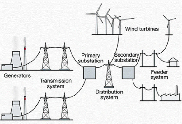
What is a ‘Smart Grid’?
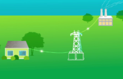
 The original power grids were constructed more than 100 years ago, when electricity demand was low. Power grids where local to individual cities and were powered by local power stations. Most homes had a very small electricity demand, such as powering up a few small lamps. The power grid was constructed as a limited one-way interaction, with electricity passing from the power station into homes. This one was interaction, with no feedback makes it difficult for the gird to respond to the current day, ever changing, rising electricity demand of the 21st century.
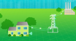
 The smart grid introduces a two-way interaction, where electricity and data can be exchanged between the generation plant and the end users. It is an ever-expanding network of computers, controls, automation and innovation working together to make the power grid, more secure, more reliable, more efficient and more environmentally friendly. Smart grid enables the generation from new generation sources such as wind, solar and tidal, as well as traditional power stations. With the ongoing advancements in smart grid technologies, a smart grid will replace the existing infrastructure of the power grid. This will leave better communication between end users and generators to help manage our electricity needs.
A recently released study by the PNNL (Pacific Northwest National Laboratory) reviewed American homeowners who had updated to new smart grid technologies to monitor and control the consumption of energy within their homes. The outcome of the study showed that the average house could have its annual electricity boll reduced by 10 percent. This could be a saving of nearly $200 billion in the USA alone. The overall result would leave homeowners with lower rates, and have the environmental impact of taking the equivalent to 30 million vehicles off the road.
With such a massive stake to gain, it is clear why there is a big drive for ‘Smart Grids’ in the 21st century.
What is ETAP?
ETAP is a fully integrated suite of software products that can be used to model an electrical power system. It offers real time calculated simulation of a designed electrical power system model. It can simulate an electrical power system from generation, to transmission, through distribution, down to the end user.
We use ETAP as a simulation package to model and predict behaviours of electrical power grids before they are constructed. This results in an efficient and safe method of designing and constructing an electrical power grid.
I propose to design an electrical power grid, which will provide power to an Electric Arc Furnace. The furnace will have many of different loads that vary from charging electrodes, to large cooling water pumps. The power for the Electric Arc Furnace will be provided from two independent sources. A Steam Generator Power Station and a Wind Farm.
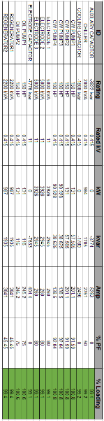
The Electric Arc Furnace will have three vertical electrodes that conduct an alternating current that forms an arc between them and the layers of the scrap metal in the furnace, causing the metal to melt. Each electrode would use 5MVA of power at 11kV. As well as high power electrodes, the Electric Arc Furnace would require additional appliances. These include water-cooling pumps, auxiliary oil pumps and induced air draft fans. These appliances will all operate at 415V.
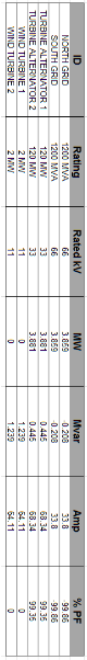
To provide power to the power hungry Electric Arc Furnace there will be two power sources located on the same site as the furnace. The first will be a Steam Power Station. Two steam-powered generators will produce a combined power output of 240MW. They will generate at 33KV and the voltage will be dropped down for distribution and transmission. The Power Station will have its own appliances similar to the Electric Arc Furnace that will enable it to generate electricity. There will be four motors used by the high-pressure steam boilers in the power station. To ensure that there is a constant supply of electricity for the power stations motors there will be a connection to the National Power Grid. This connection to the grid is will only necessary when Turbo Alternator 1 & 2 are both not generating electricity for the network. During normal operation, the circuit breakers to the grid will be open.
Two steam driven turbine generators are not the only power sources in the electrical network. Placed on the same site as the Electrical Arc Furnace will be two Wind Turbine Generators. The two Wind Turbines will generate a combined 4MW at 11KV. These two generators will be renewable energy sources that harness the energy in passing wind. They will not require fossil fuels unlike the power station. Similar to the Power Station, there will be a supply to the Wind Farm from the National Grid. This is to provide start up power for the Wind turbines. Once the turbines are operational, the link to the National Grid is will not be required. During normal operation, the circuit breakers to the grid will be open.
Transmission of power between the three sites outlined will be via overhead 66KV transmission lines. Electricity will drop down to the usable voltage at each site via transformers.
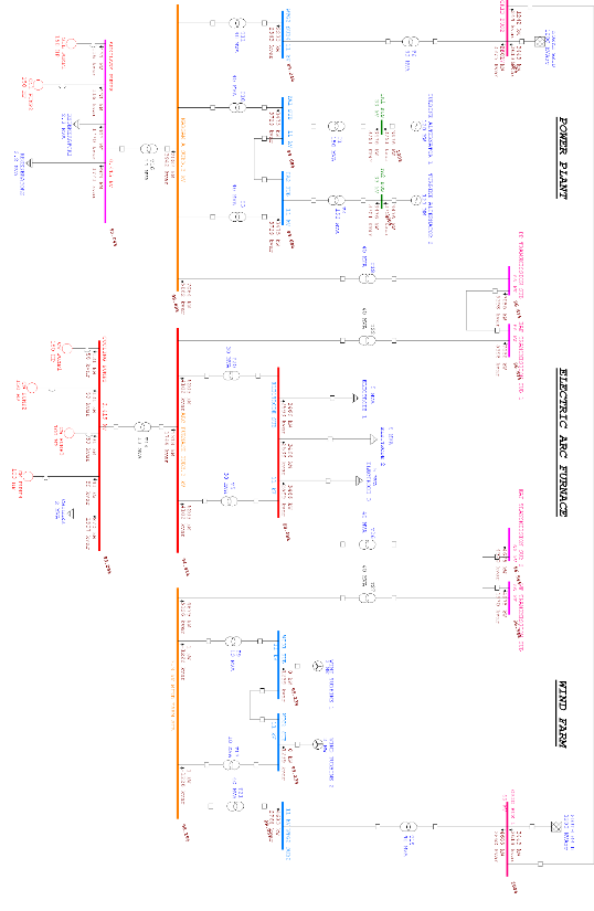
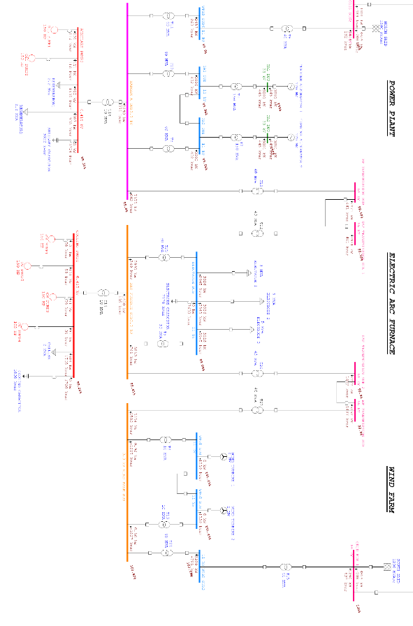
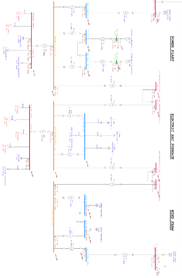
Complete Electrical Network
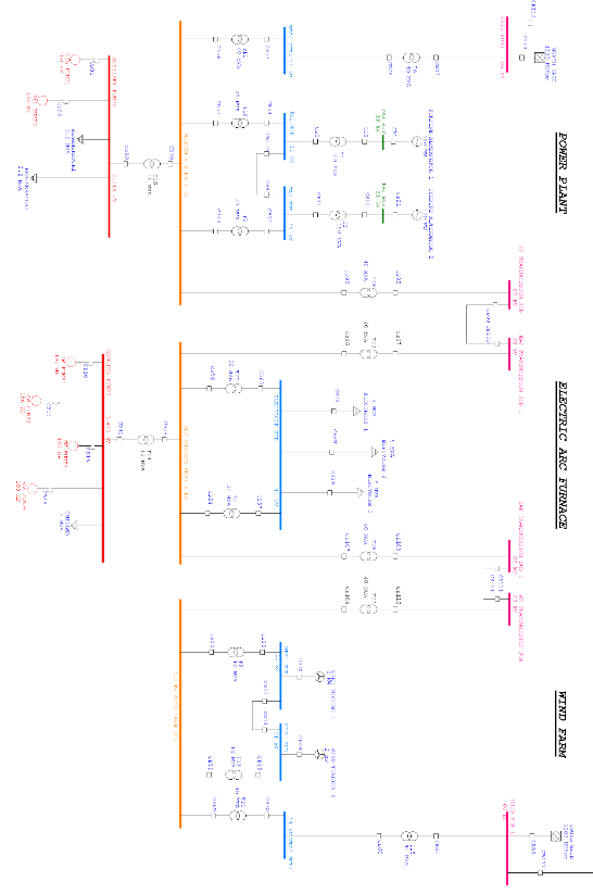
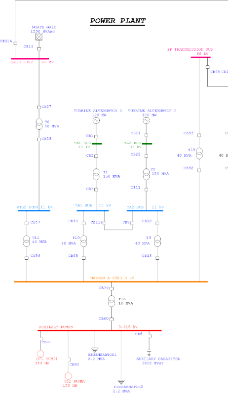
Power Plant Section
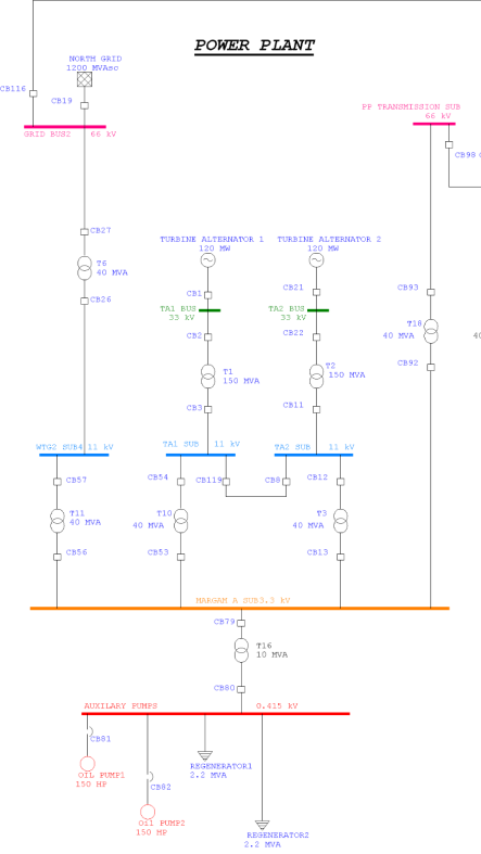 To the right is the Power Plant section of the electrical power grid. It is the main source of electricity for the grid. It provides power from two 120MW steam turbine generators. It has a link to the Utility Grid but this is only enabled when the two generators are not generating or when they running up. The Generator auxiliary pumps always require power from either the grid connection or the Turbine Alternators to enable the Turbine Alternators to generate power.
This section has two links to the rest of the electrical power grid. The first connection is to the Wind Farm Section via a 66kV line. The second connection is via a 66kV line to the Electric Arc Furnace
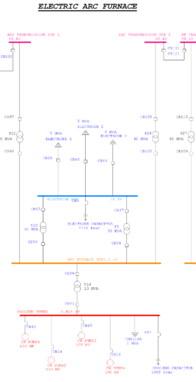
Electric Arc Furnace Section
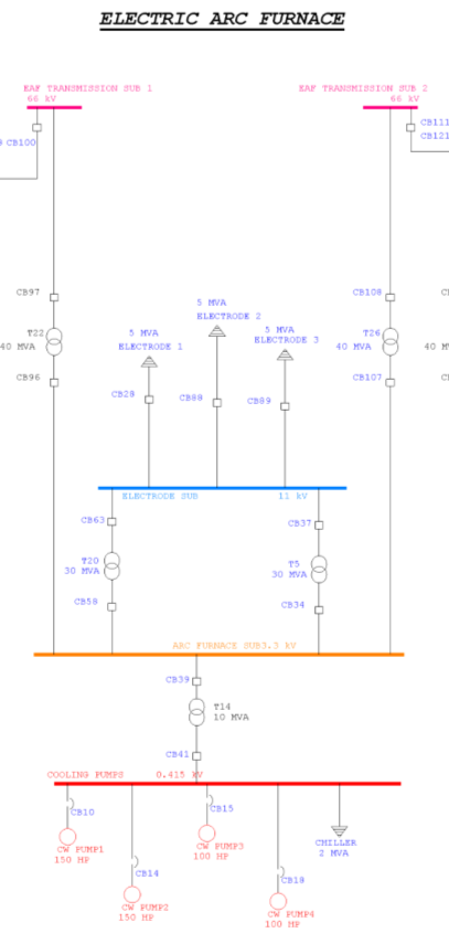 To the right is the Electric Arc Furnace Section of the Electrical Power Grid. It is the main consumer of electricity in the grid. It consumes power through three 5MVA Arc Electrodes. The Electrodes are used in the Electric Arc Furnace process to create iron from raw materials. For the process to operate successfully all three electrodes and their cooling pumps must be operational. If there is a drop in power provided to the process then it may become endangered because of the high temperatures involved. Due to this danger through loss of power, there must be redundant power supplies to the process. These supplies are provided from a 66kV line from the Power Station Section and a 66kV from the Wind Farm Section. If one were to fail there would always be a redundant supply from the other to provide power to the Electric Arc Furnace Process.
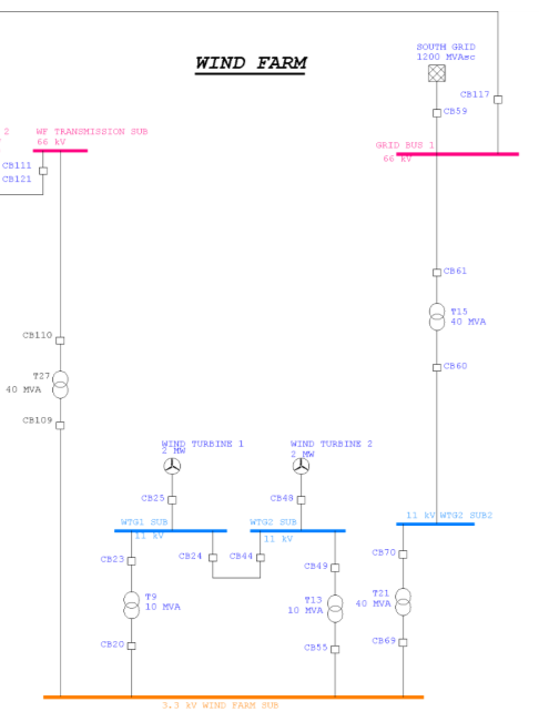
Wind Farm Section
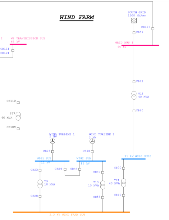 Below is the Wind Farm Section of the Electrical Power Grid. It is a source of renewable energy for the grid. Renewable energy is provided by two 2MW Wind Turbines, which generate electricity when wind turns the generator windings. There is no consumers of electricity on this section leaving it completely independent of the rest of the grid in the event that both its lines are lost. This is highly unlikely as there is a 66kV line to the Power Station Section and a 66kV to the Electric Arc Furnace Section. A second link to the Utility Grid provides a backup in case the first connection at the Power Station Section fails.
Transmission Lines
 My electrical power grid has 3 separate sections interconnected by transmission lines. These transmission connections provide redundancy protection in the event a section connection faults. The main electricity producers for the electrical power-grid operate at 11kV but for transmission purposes, the power is transmitted at 66kV. This is because line losses are much lower at higher transmission voltages over large distances. Having lower line losses improves the efficiency of transmitting the power, therefore resulting in operational cost savings.
The smaller the cross sectional area of the cables, the less the loss to heat dissipation. Large voltages require smaller surface area, resulting in less line loss. In my example of a power-grid, the voltage is being stepped up at the generating section, transmitted through the transmission line to a load section, and then stepped down to lower voltages required by the load.
This is shown in the following equation:
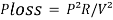
P is fixed by customer demand. R is as small as reasonably practicable by using large copper transmission lines. Therefore, line loss decreases strongly with increasing voltage.
Whilst transmission line companies wish to keep transmission lines are thick as possible to decrease the resistance in them, it has to be within financial reason.
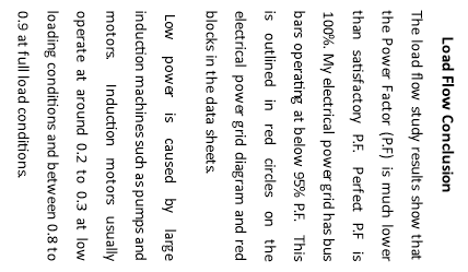
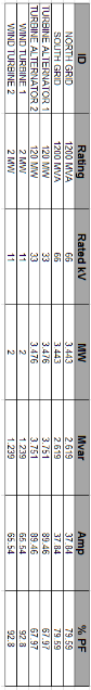
Load Flow Study
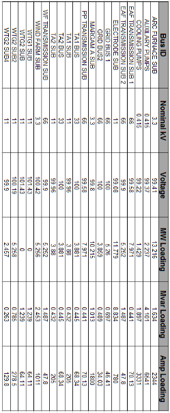
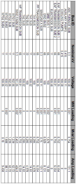
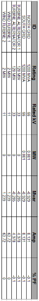
During the design stages of an electrical power-grid, a load flow study should be performed. A load flow study can outline if electrical grid voltages stay within their specified limits during normal or emergency operating conditions. The study also determines whether equipment such as conductors and transformers are overloaded. A successful load flow study can calculate the voltage at each bus, the voltage drop on each feeder, and the power flow and losses in all branch and feeder circuits.
The most common uses for load flow studies include:
- Optimisation of components
- Identifying reactive and real power flows
- Reduce kW and kVar losses
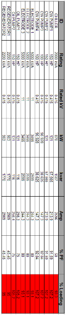
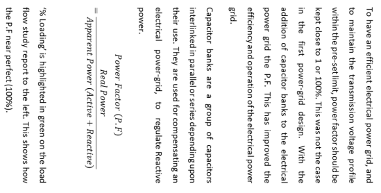
The important data retrieved from a load flow study is the voltage profile of the electrical power-grid. When voltage changes a lot throughout the system, large reactive flows will occur. This will then lead to larger real power losses. When a bus has an unacceptably low voltage, it is essential to install capacitor banks in order to provide reactive power compensation to the load.
“AN INEFFICIENT OR UNBALANCED LOAD CAN CAUSE UNPREDICTABLE BEHAVIOR”


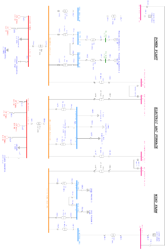 Complete Electrical Network
Power Plant Section
Below shows the redesign of the Power Plant Section of the Electrical Power Grid. Outlined by a red circle, a capacitor bank has been added to the 415V Auxiliary Pump Bus. It can be switched on and off when P.F correction is needed.
Electric Arc Furnace Section
 Below shows the redesign of the Electric Arc Furnace Section of the Electrical Power Grid. Two capacitors have been added to improve the power factor. A capacitor has been added to the 415V Cooling Pumps Bus. A capacitor has been added to the 11kV Electrode Bus. It can be switched on and off when P.F correction is needed.
 Wind Farm Section
No change has been made to the Wind Farm Section of the Electrical Power Grid.
Harmonics & Filters
Harmonic currents and voltages in an electric power grid are the outcome of non-linear loads. Harmonics in power grids produce higher temperatures electrical equipment and conductors, faults in variable frequency drives, and torque waves in motors. Power quality issues are the outcome of harmonic frequencies in the power grid. When designing an electrical power grid it is essential that of harmonics are reduced.
The significant effect of harmonics in an electrical power grid is the increase of current in the system. This is more prominent in the third harmonic, which causes a large increase in the zero sequence current. This requires a lot of consideration in when designing an electric power grid to drive non-linear loads.
Electric motors will incur losses due to large hysteresis losses caused by eddy currents in the iron core of the motor. Since the harmonics are at higher frequencies, they produce higher core losses in a motor than the power frequency would. The result of this is the increased heating of the motor core. If excessive, this will reduce the life of the motor. The 5th harmonic will introduce CEMF (counter electromotive force) in large motors, resulting in the opposite direction of rotation. CEMF does not have enough force to counteract the rotation, however it does reduce the rotating speed of the motor.
Capacitor banks have been included on the re-design of the electrical power system on to reduce the effects of harmonics and bring Power Factor to a suitable value. Their value has been specifically calculated to suit each bus bar they fed. This compensates the reduction in Power Factor.


Eaton, C. (2016). What is a smart grid. Swansea.
Energy Networks. (n.d.). Who is my network operator? Retrieved from http://www.energynetworks.org/info/faqs/who-is-my-network-operator.html
Engineering, E. (n.d.). ETAP Introduction. Retrieved from electrical-engineering-portal.com
ETAP. (2016). Network Tutorial. Retrieved from https://etap.com
Guilds, C. &. (2016). Utilities Qualifications. Retrieved from www.cityandguilds.com › Qualifications › Utilities › Utilities
Networks, S. E. (n.d.). Training Documents. Retrieved from www.spenergynetworks.co.uk/pages/training.asp
Power Skills Centre. (n.d.). Power System Protection. Retrieved from www.powerskillscentre.com/protection/power-system-protection-part-one
Siemens. (2015). HVDC Benefits. Retrieved from Siemens: http://www.energy.siemens.com/br/en/power-transmission/hvdc/applications-benefits/hvdc-benefits.htm
Udemy. (2015). ETAP Unified Electrical Grid Training. Retrieved from https://www.udemy.com/practical-etab/
Utility Engineering. (n.d.). Grid Training. Retrieved from www.utilityengineering.co.uk/electrical%20training.html
Vinici Energies. (n.d.). Smart Grid Ideoligy. Retrieved from http://www.vinci-energies.com/en/its-already-tomorrow/towards-managed-energy/smart-grids-electrical-networks-that-evolve-in-response-to-usage/
Cite This Work
To export a reference to this article please select a referencing stye below:
Related Services
View all


DMCA / Removal Request
If you are the original writer of this essay and no longer wish to have your work published on UKEssays.com then please click the following link to email our support team:
Request essay removal