Melting Performance Enhancement of Triplex Tube Latent
| ✅ Paper Type: Free Essay | ✅ Subject: Engineering |
| ✅ Wordcount: 1224 words | ✅ Published: 30 Aug 2017 |
Thermal Storage Using Fins-NanoPCM Technique
Ammar M. Abdulateef1‘*, Sohif Mat1, Jasim Abdulateef2
1 Solar Energy Research Institute, University Kebangsaan Malaysia, Bangi, Selangor, Malaysia department of Mechanical Engineering, University of Diyala, 32001 Diyala, Iraq
Latent heat thermal energy storage (LHTES) systems using phase change material (PCM) could have lower heat transfer rates during charging/discharging processes due to its low inherence of the thermal conductivity. In this study, heat transfer enhancement using internal longitudinal fins employing PCM first and nanoPCM secondly in a large triplex tube heat exchanger (TTHX) was investigated by Fluent 15 software numerically. The results showed the thermal conductivity of pure PCM (0.2 W/m.K) could be enhanced to 25% by dispersing 10% alumina (AEO3) as a nanoparticle. However, the melting time is reduced to 12% as compared with the PCM only therefore, a longitudinal fins-nanoPCM technique achieved a complete PCM melting shortly (218 minutes). Consequently, the simulation results have been validated and illustrated a good agreement with the PCM and nanoPCM experimentally.
Keywords: phase change material, triplex tube heat exchanger, melting time, longitudinal fins, nanoparticle
The major emphasis associated with most of the solar devices application is the continuous power generation during cloud transients and nondaylight hours. Thermal energy storage (TES) systems especially the latent heat thermal energy storage (LHTES) systems offer possibility to store higher amounts of thermal energy in comparison with sensible heat thermal energy storage (SHTES) systems. However, most the phase change materials (PCM) that used as storage media in the LHTES systems suffers from the low thermal conductivity (0.2 W/m.K), it often leads to uncompleted melting/solidification process and significant temperatures difference within the PCM, which in some cases can cause a material failure and system overheating.
Many researchers studied the different kinds of heat exchangers used in the LHTES systems with (PCM). Among these, concentric cylinder, shell and tube, and triplex tube heat exchanger (TTHX) [1, 2]. Most of these have been proved a high efficient for minimum
ISSN: 2367-89921 volume. Agyenim et al. [3] have been presented a significant comparison for three experimental configurations, a concentric tube system with no fins and augmented with circular and longitudinal fins. The system with longitudinal fins gave the most performance with increasing thermal response during charging and reduced subcooling in the melt during discharging. Further, the melting performance enhancement of a small scale TTHX used in LHTES system has received a significant interest by [4, 5] where numerical and experimental investigations have been made using longitudinal fins technique only to improve the melting time of simple PCM. It can be seen, longitudinal fins are most common extended surfaces have been considered in TES systems. In addition, when a triplex tube heat exchanger (TTHX) is used, the heat transfer area is also extended to the PCM and thermal performance is enhanced respect to cylinder or shell and tube heat exchanger. On the other hand, the unloading latent thermal storage, the solid-liquid interface moves away from the heat transfer surface and the heat flux decreases because of increasing the thermal resistance of the growing layer of the molten/solidified medium. This effect could be reduced by a technique of dispersing high thermal conductivity nanoparticles. The PCM melting dispersed with various volumetric concentrations of alumina (AhO3) that is heated from one side of a square enclosure is investigated numerically [6]. Wang et al. [7] improved thermal properties of paraffin wax by the addition of (TiO2) as a nanoparticle successfully without any surfactant.
The biggest challenge that is faced to investigate for both of PCM and nanoPCM was a large triplex tube heat exchanger (TTHX). Therefore, the contribution in the heat transfer rate between the PCM and the HTF are augmented using internal longitudinal fins first and dispersing a high conductivity material such as alumina (Al2O3) secondly to be formed with longitudinal fins as fins-nanoPCM technique to produce the biggest demand thermal energy stored that is required for application in air conditioning systems.
The physical configurations of the TTHX model for two cases (1) pure PCM and (2) nanoPCM are elucidated in Fig. 1. It consists of inner tube, middle tube, and outer tube that have 38.1 mm, 190.5 mm, and 250 mm in radius and 3 mm thickness, respectively with eight internal longitudinal fins each one has 121 mm long and 2 mm thickness. The inner tube and middle tube are made from copper and outer tube from steel. The water is used as HTF to transfer the heat by conviction to the walls and by conduction to the PCM or nanoPCM. The heat transfer during the PCM melting process is based on the both sides heating method where the heat is supplied from both inner and outer tubes during the charging process. The minimum temperature has been required to operate the PCM-LHTES system was approximately 90 °C.
The PCM melting numerical model is solved using Ansys Fluent 15 software based on the enthalpy-porosity technique and the finite volume method [8]. The model is drawn and meshed in a two dimensions( r, 9) as well as boundary layers and zone types are defined using
ISSN: 2367-89922 International Journal of Theoretical and Applied Mechanics
Gambit 2.4.6 software. The grids size number of the numerical model for internal longitudinal fins was calculated to 56200 as illustrated in Fig. 2.
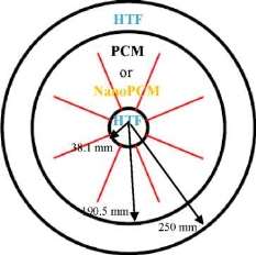
Fig. 1. Physical configurations of the TTHX-internal longitudinal fins.

Fig. 2. Distribution of the grids size number in the middle tube of TTHX-internal longitudinal fin.
For the numerical analysis of the thermal process, the following assumptions are made: (1) the melting is Newtonian and incompressible; (2) the flow in the melting process is laminar, unsteady with negligible viscous dissipations; (3) the thermo-physical properties of the HTF and PCM are independent on the temperature; (4) the heat transfer is both of conduction and of convection controlled. The effect of natural convection during the charging process is considered by invoking the Boussinesq approximation that is valid for the density variations of buoyancy force, otherwise the effect is ignored. The density variation is defined as follow: p=Pi/(J3(T-Tl) + 1) (1)
Volume 2, 2017 Ammar M. Abdulateef et al. International Journal of Theoretical and Applied Mechanics ttp://www.iaras.org/iaras/journals/ijtam
where pi is the PCM density at the melting temperature at Tt and ft is the thermal expansion coefficient. The temperature distribution and viscous incompressible flow are solved by using the Navier-Stokes and thermal energy equations, respectively. The continuity, momentum, and thermal energy equations as follows [9].
The continuity equation: dt(p) + di(pui) = 0(2)
The momentum equation:
dt(pUi)+ dj(pui uj) = pdjj Ui-dip + pgt +
Si(3)
The energy equation:
dt(ph) + dt(pAH) + di(pui h) = di(kdiT) (4) where p is the density of the PCM, ut is the fluid velocity, p is the dynamic viscosity, p is the pressure, g is the gravity acceleration, k is the thermal conductivity and h is a sensible enthalpy. The sensible enthalpy equation:
T
h = href + f^CpAT(5)
The total enthalpy H equation:
H = h +AH(6)
where href is the reference enthalpy at the reference temperature Tref, Cp is the specific heat, AH is the latent heat content of thePCM that changes between zero (solid) and L (liquid), y is the liquid fraction, which is generated during the phase change between the solid and liquid state when the temperature is Tt > T > Ts, which can be written as:
y = AH/L y = 0 y=l
(7)
if T
Y =
T-Te
if T*
Ti-Ts
From equation (3) the source term St is:
(8)
Si = C(l-y)’
where C(1- y)
y3+s
2 ui
Y3+£
(9)
is the “porosity function”
U
defined by Brent et al. [10]. C is a constant describes how sharply the velocity is reduced to zero when the material solidifies. This constant varies between 104 and 107 (105 is considered), and £ is a small (0.001) to prevent division by zero.
2.3. Boundary and initial conditions
At the initial time, the PCM was in a solid state and the temperature reached to 27 oC. A constant
temperature of the tube wall represented the HTF temperature [11, 12] that was at approximately 90 °C.The boundary conditions as follows:
Both sides heating method: at r = rt^ T = Thtf(10)
at r = rm ^ T = Thtf(11)
Initial temperature of the model: at t = 0 ^ T = Tini(12)
In case of nanoP CM, we have considere d the same conservation equations, boundary, and initial conditions mentioned above.
2.4. Thermophysical properties
Table 1 describes the thermo-physical properties of materials are used [4], the thermophysical properties of the nanoPCM are calculated [13]: The density equation:
Pnpcm0Pnp + (10)Ppcm(13)
The sp ec ific heat cap acity e quati on:
_
C,
p,npcm
Pnpcm
The late nt h e at equatio n :
_ (l – $)(.pL)pcm
(14)
j=(15)
npcm(15)
Pnpcm
The dynamics viscosity of nanoPCM is
given by [14]:
Pnpcm= 0.983e(12959®ppcm(16)
The effective thermal conductivity of the
nanoPCM, which includes the effects of particle
size (dnp), particle volume fraction (0), and
temperature dependence as well as propertie s of
the base PCM. The particle subject to Brownian
motion is also given by [14]:
Knp) 0
Knp + 2Kpcm 2 jj^pcm
npCmKnp+2Kpcm+2(Kpcm-Knp) 0 Pcm
+
5 x 1 0 4 yk g0ppCmcp,pcmJPnpdnp f(T’ 0)
(17)
where B is the Boltzmann constant (1.381 x 10⁻²³ J/K) and yk = 8.4407(1000)-10â„¢4. f(T, 0) = (2.8217 x 10⁻²⁰+ 3.917 x 10⁻³) -+ (-3.0669 x 10⁻²⁰- 3.91123 x
Tref
10-3)(18)
where Tref is the reference temperature = 273 K.
We have evaluated in the equation (17), the effects of nanoparticle diameter (dnp = 20 nm), nanoparticle volume fraction (0 = 10%), and the reference temperature (Tref = 237 K).
ISSN: 2367-8992
3
Volume 2, 2017

Ammar M. Abdulateef et al.
Table 1. Thermophysical properties of PCM, copper, and alumina (AI2O3).
|
Properties |
PCM (RT82) |
Copper |
A^O3 |
|
Density, solid, ps (Kg/m3) |
950 |
8978 |
3600 |
|
Density, lquid, pi (Kg/m3) |
770 |
– |
– |
|
Specific heat, Cpi , Cps (J/kgK) |
2000 |
381 |
765 |
|
Latent heat of fusion, L (J/kg) |
176000 |
– |
– |
|
Dynamic viscosity, p (kg/m.s) |
0.03499 |
– |
– |
|
Melting temperature, Tm (K) |
350.15 358.15 |
2345 |
|
|
Thermal conductivity, K fW/m.K) |
0.2 |
387.6 |
36 |
|
Thermal expansion coefficient, (1/K) |
0.001 |
– |
– |
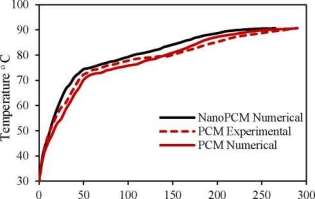
A schematic diagram of the LHTES system apparatus is illustrated in Fig. 3. The middle tube of TTHX is filled with 100 kg PCM first. The present numerical model for PCM and nanoPCM has been validated experimentally with PCM as illustrate in Fig. 4. A comparison resulted was not exceeded in percentage errors of 3% and showed a good agreement with an experimental test for two cases. Moreover, the average temperature of the PCM was 27 °C when melting process started and the HTF charging temperature by both sides heating method [4] was 90 °C with an experimental mass flow rate 37.5 L/min.
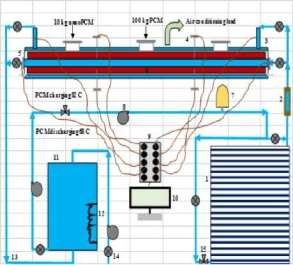
Fig. 3. Schematic diagram of experimental apparatus of LHTES system, which includes; 1. Evacuated tube solar collectors (ETSC), 2. Flow meter, 3. Triplex tube heat exchanger (TTHX), 4. Thermocouple J-type, 5. Sensor (water), 6. Internal longitudinal fin, 7. Pressure vessel tank, 8. Pump, 9. Data acquisition, 10. Computer, 11. Water storage tank, 12. Electrical heater, 13. Pipes, 14. Valve two ways, 15. Valve three ways.
ISSN: 2367-89924
International Journal of Theoretical and Applied Mechanics
Time (min)
Fig. 4. Validation of an experimental and numerical model
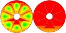
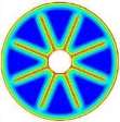
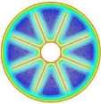
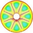
The isothermal contours of the PCM in TTHX with internal fins at different times (10, 60, 120, and 247 min) are elucidated in Fig. 5. firstly, heat transfer occurred between the hot wall of the tube and solid surface of the PCM by conduction, which dominated the melting process at the early stage and caused a very thin layer of the liquid that is surrounded the longitudinal fin surface and hot wall of the tube while the rest of the PCM remained solid without any phase change because of the effects of natural convection were limited. After 10 minutes, small convection cells are formed between the fins wall and subsequently expanded to the middle tube. Over time, cells convection emerged and facilitated the formation of the large convection cells at 60 minutes that are expanded to the bottom part of tube at 120 minutes because heat transfers by fins. The full PCM melting was accomplished at 247 minutes.
The thermo-physical properties of the nanoPCM with various volumetric concentrations of the alumina (AfO3) are calculated using equations (13-17). It is found that, the specific heat and latent heat of the nanoPCM are lower than the pure PCM whereas the thermal conductivity and dynamic viscosity of the nanoPCM are higher than the pure PCM, see Table 2. This variation in
Volume 2, 2017


Liquid fraction
International Journal of Theoretical and Applied Mechanics
Ammar M. Abdulateef et al.http://www.iaras.org/iaras/journals/ijtam
the thermal conductivity and dynamic viscosity agree well with the results that reported in [6]. Moreover, augmenting the alumina nanoparticle (AhO3) volume concentrations caused to reduce the PCM melting time, see Fig. 6. Consequently, the PCM with 10% alumina (AhO3) is considered

sssssssssssssssasssss
10 min60 min
120 min247 min
Fig. 5. Isothermal contours of the PCM in TTHX- longitudinal fins.
Table 2. Variation of the thermal conductivity and dynamic viscosity of nanoPCM.
|
Volumetric concentration |
Thermal conductivity k (W/m.K) |
Dynamic viscosity g (kg/m.s) |
|
Simple PCM |
0.2 |
0.03499 |
|
Nano-PCM (1% M2O3 ) |
0.206 |
0.0121161 |
|
Nano-PCM (4% M2O3) |
0.225 |
0.0485 |
|
Nano-PCM (7% M2O3) |
0.245 |
0.084812 |
|
Nano-PCM (10% M2O3 ) |
0.265 |
0.121161 |
1.2
0100200300
Time (min)
Fig. 6. Effect of the nanoparticle concentrations.
4.2.1. Nanoparticle-internal fins technique
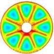
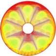
The isothermal contours of the fins-nanoPCM technique in TTHX at different times (10, 60, 120, and 218 min) are shown in Fig. 7. A significant reduction in time was observed by dispersing 10% nanoparticle to the PCM when the absorbed energy was stored to the required load under the effects of both sides heating method, which is augmented the conduction heat transfer rate. Therefore, the full melting of the PCM is completed at 218 minutes. Consequently, the nanoparticle plays a significant role in the melting rate enhancement where the thermal conductivity of simple PCM (0.2 W/m.K) could be enhanced to 25% significantly that is caused to increase the conduction heat transfer.
10 min60 min
120 min218 min
Fig. 7. Isothermal contours of the fins-nanoPCM technique.
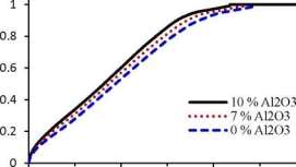
Figure 8 illustrates liquid fraction vs. melting time for the PCM and nanoPCM in TTHX- internal longitudinal fins. As shown, the PCM melting time is reduced using nanoPCM to 12% as compared to the PCM only. The PCM melting retardation was reduced because of augmenting the thermal conductivity of PCM effectively.

ISSN: 2367-8992
5
Volume 2, 2017
Liquid fraction
Ammar M. Abdulateef et al.
International Journal of Theoretical and Applied Mechanics
Consequently, the model of fins-nanoPCM is considered the most efficient technique to achieve the PCM melting shortly (218 min).
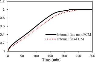
Fig. 8. Liquid fraction vs. melting time for the PCM and nanoPCM in TTHX-intemal longitudinal fins.
Heat transfer enhancement for a large triplex tube heat exchanger (TTHX) has been represented the biggest challenge in LHTES system. The results showed the thermal conductivity of simple PCM (0.2 W/m.K) could be enhanced to 25% by dispersing 10% alumina and the melting time is reduced to 12% as compared with the PCM only. Consequently, the model of fins-nanoPCM has been considered the most efficient technique based on both sides heating method to achieve the PCM melting shortly (218 min). However, the numerical results have validated and showed a good agreement with the PCM and nanoPCM experimentally.
BBoltzmann constant (J/K)
Cmushy zone constant (kg/m3s)
Cpspecific heat (J/kg.K)
gi gravity acceleration in the i-direction (m/s2)
Henthalpy (J/kg)
HTFheat transfer fluid
Llatent heat fusion (J/kg)
kthermal conductivity (W/m.K)
ppressure (Pa)
Tmmelting temperature (oC or K)
uvelocity component (m/s)
Simomentum source term in the i-direction (Pa/m)
pfluid density (kg/m3)
yliquid fraction
Pthermal expansion coefficient (1 /K)
Zcorrection factor
The authors gratefully appreciate a financial support that provided by Solar Energy Research Institute(SERI),University Kebangsaan Malaysia (UKM), Malaysia.
- H. Niyas, P. Muthukumar, Performance analysis of latent heat storage systems, International Journal of Scientific & Engineering Research 4 (2013) 2229-5518.
- Y.L. Jian, Numerical and experimental investigation for heat
transfer in triplex concentric tube with phase change material for thermal energy storage, Solar Energy 32
- 85-977.
- F. Agyenim, P. Eames, M. Smyth, A comparison of heat transfer enhancement in a medium temperature thermal energy storage heat exchanger using fins, Solar Energy 83
- 1509-1520.
- S. Mat, A.A. Al-Abidi, K. Sopian, M.Y. Sulaiman, A.T. Mohammad, Enhance heat transfer for PCM melting in triplex tube with internal-external fins, Energy Conversion and Management 74 (2013) 223-236.
- A.A. Al-Abidi, S. Mat, K. Sopian, M.Y. Sulaiman, A.T. Mohammad, Heat transfer enhancement for PCM thermal energy storage in triplex tube heat exchanger, Heat Transfer Engineering, vol. 37, pp. 705-712, 2016.
- A.V. Arasu, A.S. Mujumdar, Numerical study on melting of paraffin wax with Al2O3 in a square enclosure, International Communications in Heat and Mass Transfer 39 (2012) 8-16.
- J. Wang, H. Xie, Z. Guo, L. Guan, Y. Li, Improved thermal properties of paraffin wax by the addition of TiO2 nanoparticles, Applied Thermal Engineering (2014) 1-7.
- S.V. Patankar, Numerical heat transfer and fluid flow, McGraw Hill, New York, 1980.
- A.A.R. Darzi, M. Farhadi, K. Sedighi, Numerical study of melting inside concentric and eccentric horizontal annulus, Appl Math Model 36 (2012) 4080-4086.
- A.D. Brent, V.R.Voller, K.J. Reid, Enthalpy-porosity technique for melting convection-diffusion phase change: application to the melting of a pure metal, Numer Heat Transfer 13 (1988) 297-318.
- C. Guo, W. Zhang, Numerical simulation and parametric study on new type of high temperature latent heat thermal energy storage system, Energy Convers Management 49 (2008) 27-919.
- M.J. Hosseini, A.A. Ranjbar, K. Sedighi, M. Rahimi, A combined experimental and computational study on the melting behavior of a medium temperature phase change storage material inside shell and tube heat exchanger, International Communications in Heat and Mass Transfer 39 (2012) 1416-1424.
[ 1 3 ] A.P. Sasmito, J.C. Kurnia, A.S. Mujumdar, Numerical evaluation of laminar heat transfer enhancement in nanofluid flow in coiled square tubes, Nanoscale Research Letters 6 (2011) 376.
[14] R.S. Vajjha, D.K. Das, PK. Namburu, Numerical study of fluid dynamic and heat transfer performance of Al2O3 and CuO nanofluids in the flat tubes of a radiator, International Journal of Heat Fluid Flow 31 (2010 ) 613-621.
ISSN: 2367-8992
6
Volume 2, 2017
Cite This Work
To export a reference to this article please select a referencing stye below:
Related Services
View all


DMCA / Removal Request
If you are the original writer of this essay and no longer wish to have your work published on UKEssays.com then please click the following link to email our support team:
Request essay removal