Mechanical Strength of Mild Steel
| ✅ Paper Type: Free Essay | ✅ Subject: Engineering |
| ✅ Wordcount: 1444 words | ✅ Published: 31 Aug 2017 |
Introduction
CE 2.1 One day on National Geographic channel I was watching a program in which they were experimenting with the finite element analysis software to observe structure and thermal load effects on the wing of Boeing 747’s wing. Luckily, during the same time, in my 8th semester back in 2013 we were taught the introduction to Finite Element Methods by our professor, Dr. Ijaz Ahmed Chaudhary in University of Engineering and Technology, Lahore. The curiosity in that subject laid the initial foundations of my interesting project named as Drop Test Calculations for Mild Steel where I worked as a “Team Leader”. This experience paved my way to two more leadership roles.
Background
CE 2.2 It was almost four years in UET Lahore. And being a student of engineering I almost had the fundamental knowledge of the field by that point. I wanted to use my theoretical knowledge in some practical way. I had already studied the mechanics of materials 1 and 2. And performed various experiments in lab to find out the material properties such as; ductility, malleability, brittleness and toughness. In 8th semester ANSYS was being used as external load analysis software in Finite Element Analysis course. I was assigned a project to select a topic and perform it in the lab and as well as analyze it using ANSYS. That was a good opportunity to gain practical experience and integrate the knowledge of Mechanics of Materials and Finite Element Analysis.
Nature of Project:
CE 2.3 This project included the calculation for drop testing of mild steel. In industry and real world different items and object face different kind of environmental conditions. Drop testing was used for shock loading effects. First of all, theoretical modeling was done for drop table to check either items can survive shock or not. Then commercial finite element software was used to investigate the response of drop table.
Objective of the Project:
CE 2.4 The objective of the report was to determine mechanical strength of mild steel. I had to use drop testing method & then I investigated its behavior on finite element software.
Nature of My Particular Work Area
CE 2.5 In this project, I had to perform calculations for drop table by taking it as a fixed beam at both ends and applying a sinusoidal shock load of 100 gram. Then calculations were made to calculate the maximum binding stress produced in drop table.
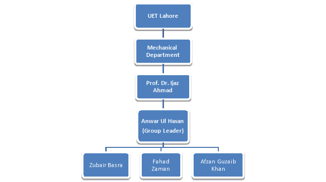
CE 2.6 Organizational Structure
CE 2.7 Statement of Duties
Being leader of the group my scope of duties included:
- To plan the project for timely completion.
- To make work packs to ensure health and safety.
- Conduct meeting with members and supervisor for mutual feedback.
- Theoretical calculation of drop test mechanism on mild steel.
- Report writing and technical presentation.
Personal Engineering Activity
CE 2.8 I started with literature review about drop testing and FEA on internet and library. Subsequent discussions with my professor led me up to kick off my calculations. The second step of course was to select certain parameters and their dimensions for drop testing. These parameters are given in the table below.
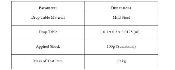
The drop table material and the shock load value was assigned to us by our professor. I chose the dimensions of the table and mass of test item carefully. If the mass of the table is too less it won’t be able to bear the shock itself let alone the test item. To make things more clear, test item is always on the top of table when shock is being applied on it.
Now the next step was to calculate the weight of the table.
Table thickness = d = 0.0125m
Table length = l = 0.3m
Table width = b = 0.3m
Weight of the table =W1 = density * volume*g
W1 = 86.75 N
Weight of the test item = W2= 20KG = 196 N
Total Weight = W = W1+W2 = 282.75 N
Moment of Inertia = I = 4.88 * 10-8 m-4
The rest of the calculations are shown below
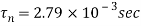
To calculate shock factor, F, I needed to calculate  . Shock duration,
  , is 0.01 s and the natural time period,
  , is given as below:

Where , , is the static deflection and is calculated as follows:

Where,
W = Weight per unit length, N/m = 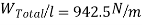
E = Young’s modulus of Elasticity of Mild Steel = 210 x 109 N/m2
So, after substituting the values in the above equation
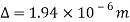
Hence,
As a result,

CE 2.9 By using the graph below in Figure 1, we deduce that F factor comes out to be 1.2.
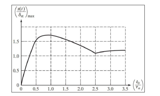
Figure 1: Calculation of Factor F
Moreover, some of the basic calculations are done below:
Dynamic load is calculated as Pd = F * M * A
A= Applied Shock = 100g
M= Total Weight/gravitational force (g)
Therefore ,
Pd = 33930 Newton
Now, I have to calculate maximum bending stress
Max Bending Stress =(Bending Moment * Distance from axis)/ Inertia
Max Bending Stress = 48.88 MPa
I verified the bending moment calculations as they were performed by my team mate and it is beyond the scope of this report to discuss it fully here.
CE 2.9 According to the principle of mechanics, if the maximum bending stress produced by the applied load is less than the ultimate tensile strength of the material then the material can withstand the applied load without failure and vice versa. In this case, since the ultimate tensile strength of mild steel is 165 MPa which is greater than the maximum bending stress of 48.88 MPa produced by the applied load, drop table will easily sustain the 100 g shock loading.
CE 2.10 Computational dynamics came into play in the form of FEA as I used ANSYS to simulate static deflection of the drop table subjected to 100 g shock loading. The load is applied on the top surface of drop table in form of pressure and both ends of the table are fixed by using fixed support. Material properties used for the drop table are shown in the figure 2 below.
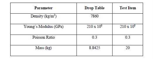
Figure 2: Material properties of the test piece
CE 2.11 I still remember that there came a point where my team was very much stressed out because of the criticality of the extensive calculations involved. In fact, my team failed in couple of iterative processes and they wanted to give up on this project. I summoned a meeting where I emphasized on the fact that every failure is itself a step towards success. By omitting those factors which are causing us disappointment should be identified and removed. My team appreciated the gesture and went on to complete the project with more enthusiasm and that is when we finally got the 3D mesh of the work piece as shown below in figure 3:
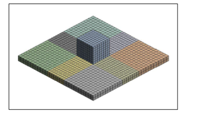
Figure 3: 3D meshing of the drop table
The parameters for meshing details are show in figure 4 below.
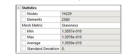
Figure 4: Meshing parameters obtained during FEA
CE 2.11 After the meshing, the sinusoidal shock load of 100 g, shown in figure below, depicts that the maximum Von Mises stress produced in drop table amounts to be 50.23 MPa. Our theoretical calculated maximum stress comes out to be 48.88 MPa. Again, I can surely say that this stress is within the bearable load limits of the table load and hence won’t fracture. The stress patterns are shown in figure 5 below.
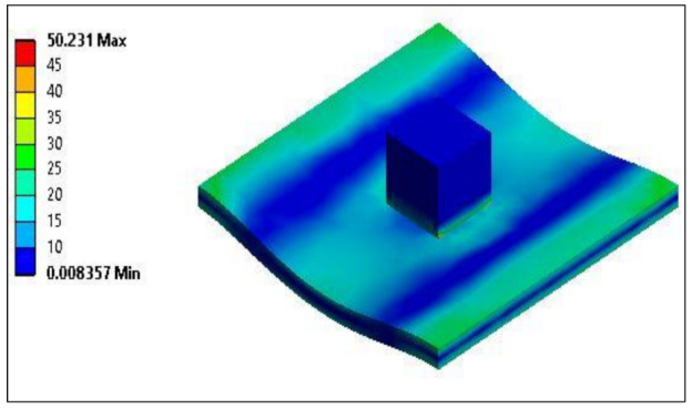
Figure 5: Static structural analysis of drop table
CE 2.12 Mild steel is a very stiff material so a very high shock wave is generated when drop table hits the mild steel. On the other hand, due to its stiffness the duration of the shock is very low. In case of mild steel peak shock value calculated was 55.84 g when a drop table is dropped from a height of 330 m. Below figure 6 depicts this behavior in the form of a graph.
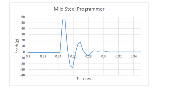
Figure 6: Shock loading VS Time Graph
CE 2.13 Von Mises stress contours produced when drop table strikes with mild steel attached sensors are shown in the figure below. Stress contours clearly shows that high stresses are produced in region where drop table makes contact with the object. Highest stress produced is 49.9 MPa as shown in figure 7.
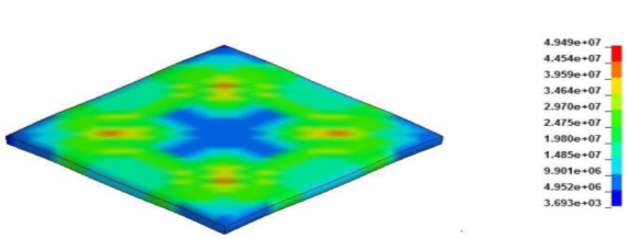
Figure7: Von Mises stress contours produced in case of mild steel programmers contact
CE 2.14 As we had to use Lab with heavy machinery and metal pieces, I made sure that every used proper safety procedure such as wearing PPE. Toolbox talks and near miss discussions were conducted before every session. That was the reason project was completed without any accidents.
Summary
CE 2.15 The timely completion of this project boosted up my technical knowledge and had an ever lasting impact on my people and time management skills. Later on, during one of my internships I realized that my quality check department was facing a material failure issue. Keeping in view this project I performed the drop testing and deduced that the material wasn’t strong enough to resist the stresses and buckled in extreme loading conditions. My study was well praised and they switched from Steel to Aluminum and since then have got fewer failures.
Cite This Work
To export a reference to this article please select a referencing stye below:
Related Services
View all


DMCA / Removal Request
If you are the original writer of this essay and no longer wish to have your work published on UKEssays.com then please click the following link to email our support team:
Request essay removal