Material Failure Analysis
| ✅ Paper Type: Free Essay | ✅ Subject: Engineering |
| ✅ Wordcount: 2588 words | ✅ Published: 30 Aug 2017 |
Question 1)
There are axles on all vehicles such as cars as the axle supports the wheels parallel to the opposing wheel whilst holding the balance of the body of the car. It also transmits torque from the axle to the wheels to give it power that is efficient in the movement of the car. Other vehicles such as heavy-duty trucks will not have a shaft like the front beam axle therefore it “serves only as a suspension and steering component.” (Vehicle Axle, 2017)

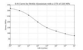
It is likely that the rear wheel axle was failed by fatigue as this is very common. The axle must be able to carry the weight of the vehicle and any cargo that has been loaded. This is usually directed at heavier vehicles such as commercial vehicles that carry around goods. Over time the axle could wear down if excess stress is applied to the axle. This is called a high-cycle fatigue which can be shown by an S-N curve otherwise known as the Wohler curve. August Wohler “was a German railway engineer, best remembered for his systematic investigations of metal fatigue.” (August Wohler, 2016) As we can see from Figure 1, this is a Wohler curve example for brittle aluminium that shows when you apply stress over the Ultimate Tensile Strength (UTS), the life reduces over time and wears out and would break which relates to if stress above the UTS is applied on the rear axle it could also lead to it breaking.
When too much stress (more than what the recommended axle capacity) is applied to the vehicle, the axle begins to form small cracks wearing down the structural integrity over time. Stress on the rear axle could also be applied from things such as driving in harsh conditions like bumpy roads or potholes. Another very common reason (especially older vehicles) if the vehicle does not get the proper maintenance that could damage the vehicle over time from parts such as shafts, gears, components of the axle or “rusted parts that have not been cared for”. (How do you break an axle?, 2017)Â These therefore could potentially lead to the axle breaking by fatigue over time.

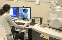
 The way we can analyse if the rear axle was broken on impact is by using a method called fractography. Fractography is a method that is used “to determine the cause of failure of engineering structures”. (Fractography, 2017) For material science, fractography is used to check crack growth behaviour. The method used for this is carried out by using an optical microscopy (figure 2) with angled lighting on the broken axle to find out the degree of cracking and possibly the origins. This process is enough to pinpoint the cause of the cracking and the growth pattern. Common reasons that could cause the material to crack are contaminations, stress concentrations etc.
In conclusion many factors can separate if the rear axle breaking was caused by fatigue failure or failure on impact. It could vary for reasons such as if the vehicle had been carrying a heavy load over time for example a commercial vehicle that carries goods that is heavier than the Ultimate Tensile Strength (UTS) of what the axle can hold. Proven by the Wohler curve over time the life cycle of the axle will wear down and eventually break. For vehicles that do not carry loads that apply excess stress on the rear axle, the reasoning of the axle breaking could be from natural causes from the environment such as speeding over potholes, parts rusting or no proper maintenance on the vehicle could lead to the structural integrity breaking down over time causing it to be in an accident. By using fractography on the broken axle could show leads to why the accident was caused by looking at the cracks and the pattern of the spread to see if it was caused by load or not.
Question 2)
A pulley is used to lift heavy loads or to change the direction of forces applied. It consists of a wheel with grooves on an axle that can be driven with pulley systems like wire rope, cable, chain etc. These pulleys can operate using applied human force to lift heavy objects. The reason why humans can lift heavy objects with the pulley is because the pulley system such as wire rope transmits the tension force around the pulley allowing humans use no effort because there is no energy loss because of the friction. However for much heavier items that humans cannot lift, machinery is used such as cranes. If the “pulley system does not dissipate or store energy, then its mechanical advantage is the number of parts of the rope that act on the load” (Pulley Systems, 2017).
Wire ropes are usually made from a non-alloy carbon steel with a very low “carbon content of 0.4 to 0.95%.” (Carbon steel rope, 2017) This allows the rope to have an extremely high strength that can hold large tensile forces and be able to operate sheaves (pulley with a groove) with somewhat small diameters. If no chemical/mechanical damage, excessive heat or corrosion is involved in the wire rope failing then the rope will fail in the sector which has been exposed to the highest amount of abrasion and fatigue. This means that the likeliest sector that the wire rope failure will occur can be predicted. Wire ropes also vary from different aspects such as the number of outer strands and the size of the core. For example if you had less outer strands, the core would not be able to hold the load however the outer 
 strands will hold it instead. On the other hand, if you had more strands, the core would be bigger therefore it would hold the load however the outer strands become loose over time but that would not make the rope fail.

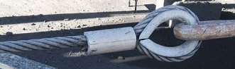 One way the wire rope could have failed is the end of the rope wearing out over time in a Flemish eye and could potentially come apart causing it to fail due to the load exceeding the weight limit of the bond between the Flemish eye and the wire rope. There are many ways that the wire rope can be terminated to prevent and stop this from happening. These include methods such as thimbles, clamps, sockets etc. with termination efficiencies that range from 70-100%. However there are also cons with some termination methods such as thimbles. There is the risk that when the wire rope is terminated, it could bend too tightly “especially when the loop is connected to a device that concentrates the load on a relatively small area”.(Wire rope bend, 2017) The wire ropes need to have a strong structure requiring it to have been stressed by things such as wear and corrosion. It also needs to be inspected using a “magnetic method capable of detecting inner wire breaks.” (Wire rope Safety, 2017)
A frequent cause for wire rope failure is corrosion. This is due to the use of a little lubrication or lubrication that has not penetrated inside the rope. The rope inspector will not see the wire rope corroding due to lubrication on the outside however the rope would be destroyed internally by corrosion and abrasion and when it goes to lift a heavy weight, it would create a 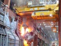 great amount of damage. Another way damage can be caused it called “jumping the sheave” which is not where the rope does not slip/jump out of the sheave but it fails to get into the sheave of the wheel instead. Steel wire ropes have a high melting point therefore can be used in hot environments such as “Ladle cranes”
  (Ladle cranes, 2017) as seen in Figure 4. However if the steel wire ropes stay in the heat for too long, the material anneals therefore making it dangerous.

 There are multiple ways we can analyse why the wire rope failing one of them being microscopic analysis. The wire rope can be analysed through this method to see the cracks in the steel. It can then be run through a “Scanning Electron Microscope” (Scanning electron microscope, 2017) done by X-ray analysis and X-ray mapping which can show every forking point of the wire as if the wire was extremely brittle.
Pulley systems have been used for a very long time and can be traced back to “Mesopotamia in 1500 B.C.” (When was the pulley invented?, 2017) so we can see that it is a very useful technique to present day. Therefore I conclude that the reason behind the rope failing is due to fatigue. There are several safety precautions for exceeding the weight limit such as Flemish eye. However there too many fatigue reasons that outweigh the limit of the rope such as the amount/types of stresses and environmental factors that can also be analysed through SEM (Scanning Electron Microscope) to see cracks in the wire rope.
Question 3)

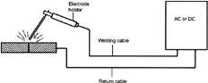 Arc welding is a common method that fuses metals together. The way this is done is by using a welding power supply that could be alternating (AC) or direct (DC) current that creates “an electric arc between an electrode and the base material.” (Arc welding, 2016) This then melts the base material to its welding point and then the melted metal will create a weld between the metals. The weld will then cool fusing them together (can be seen in figure 7). Arc welders must be trained and equipped with PPE (Personal Protective Equipment) such as visors due to the fact that arc welding produces harmful Ultraviolet radiation and toxic fumes from metals. If they do not take these precautions UV radiation can lead to ocular damage and the toxic fumes can lead to occupational disease.

 A major defect that arc welding could have is cracks (Figure 8). There are many types of cracks within the weld and it only takes one type to fail a weld inspection. You cannot go over the crack with more welding to cover it up as the weld will not be strong over use especially in relation to the missile leaning on the steel which would not last long and could cause damage therefore the weld needs to be filed/grinded out and done again.
One type of cracking is called “cold cracking”. It is not noticeable at first however over time it will be because hydrogen absorbs into the weld puddle affecting the weld. This could be because of moisture seeping into the electrode before welding. Another type of cracking is called “hot cracking” and this is noticeable right after welding. The reasoning behind this crack could be poor joint design that would not diffuse the heat. One of the other reasons behind hot cracking could be impurities such as the presence of sulphur in the welding metal which could cause problems such as change the cooling within the weld.
Many precautions can be taken to avoid cracks within the arc weld such as checking your welding equipment i.e. test your machine before you generate current to the electrode and keep your welding rod and metals in dry conditions so hydrogen or sulphate does not affect your weld. You should also make sure your plates are clean and grinded well so the arc weld fit without any problems such as the welding joint.
Steel has a very low carbon content between 0.05-0.25% which is easy to weld with because it would not harden by heat treatment. Therefore there will be less hardened zones in the heat affected zone because as carbon content increases, welding gets harder because of the quenching action. The microstructure of the weld metal is needed for the alloy of the carbon steel but in carbon, carbon manganese and micro alloyed steel, the weld metal structure is mostly affected by the welding. The structure of Carbon steel is usually affected by things such as the cooling time, plastic strain, composition etc.
The Heat Affected Zone (HAZ) is the area of the steel plates that has had “microstructure and properties altered by welding” (Heat-affected zone, 2016). The speed and temperature of the 
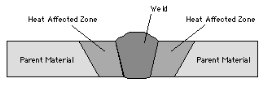 welding plays a big role as it decides the spread of heat onto the parent material (HAZ diagram figure 9). Different types of processes such as electron beam welding gives off high concentrated limited amounts of heat that results in Heat affected zone. For arc welding in steel, the HAZ is split into three sections being the intercritical, supercritical and subcritical from a metallurgical point of view. Heat affected zones are impossible to see because it makes it hard to manage the bending angle therefore “the only way to remove the entire extension of the HAZ is to machine it away” (Dealing with HAZ, 2017).
Methods to analyse weld testing are utilized to guarantee the quality of the weld after it is finished. For the most part this refers to testing and analysis concentrated on the quality and quality of the weld, yet it may refer to actions to check for the position, intensity of welds. A common method to analyse these welds are image-based such as X-ray using Machine Vision (MV). This method is done by and inspector manually to look at images of the weld and come up with a conclusion of the quality and correctness of the weld.
In conclusion, there are many deciding factors such as the microstructure when it comes to its behaviour and properties. We know that the cooling rate and composition of the welding is important in the formation of microstructures in the welding metal. I would recommend welding the steel in controlled situations at described above to prevent cracks. We know the carbon content of the steel increases therefore the weldability decreases and the hardness increases. I believe arc welding in a controlled situation such as dry conditions and testing machinery before use is a low risk of being affected by things such as sulphate and hydrogen.
Question 1)
- Vehicle Axle (2017) in Wikipedia. Available at: https://en.wikipedia.org/wiki/Axle#Vehicle_axles
- August Wohler (2016) in Wikipedia. Available at: https://en.wikipedia.org/wiki/August_W%C3%B6hler
- File: BrittleAluminium320MPa S-N curve.svg (2016) in Wikipedia. Available at: https://en.wikipedia.org/wiki/File:BrittleAluminium320MPa_S-N_Curve.svg
- How do you break an axle? (2017) Available at: https://www.reference.com/home-garden/break-axle-7c5da780a7e83eb2
- Fractography (2017) in Wikipedia. Available at: https://en.wikipedia.org/wiki/Fractography
- https://en.wikipedia.org/wiki/Optical_microscope#/media/File:Optical_microscope_nikon_alphaphot_%2B.jpg
Question 2)
- Pulley Systems (2017) in Wikipedia. Available at: https://en.wikipedia.org/wiki/Pulley#Rope_and_pulley_systems
- Carbon steel rope (2017) in Wikipedia. Available at: https://en.wikipedia.org/wiki/Wire_rope#Construction
- Wire rope Safety (2017) in Wikipedia. Available at: https://en.wikipedia.org/wiki/Wire_rope#Safety
- Ladle cranes (2017) Available at: http://www.casar.de/Rope-Selection/Ladle-Cranes
- Scanning electron microscope (2017) in Wikipedia. Available at: https://en.wikipedia.org/wiki/Scanning_electron_microscope#Materials
- SEM Scanning (no date) Available at: https://www.mri.psu.edu/materials-characterization-lab/characterization-techniques/scanning-electron-microscopy-sem
- When was the pulley invented? (2017) Available at: https://www.reference.com/history/pulley-invented-8dcaf2574d30b8ea
- Wire rope bend (2017) in Wikipedia. Available at: https://en.wikipedia.org/wiki/Wire_rope
Question 3)
- Arc welding (2016) in Wikipedia. Available at: https://en.wikipedia.org/wiki/Arc_welding
- Welding diagram (2003) Available at: http://www.globalspec.com/reference/80954/203279/chapter-6-metal-arc-welding-with-coated-electrodes
- Arc Welding Cracks (2016) in Wikipedia. Available at: https://en.wikipedia.org/wiki/Welding_defect#/media/File:Welding_cracks.svg
- Heat-affected zone (2016) in Wikipedia. Available at: https://en.wikipedia.org/wiki/Heat-affected_zone
- Dealing with HAZ (2017) Available at: http://www.thefabricator.com/article/shopmanagement/all-you-need-to-know-about-the-heat-affected-zone
Cite This Work
To export a reference to this article please select a referencing stye below:
Related Services
View all


DMCA / Removal Request
If you are the original writer of this essay and no longer wish to have your work published on UKEssays.com then please click the following link to email our support team:
Request essay removal