Investigation of Fracture Energy – GF
| ✅ Paper Type: Free Essay | ✅ Subject: Engineering |
| ✅ Wordcount: 3326 words | ✅ Published: 31 Aug 2017 |
ABSTRACT
Concrete’s inherent brittleness, low tensile strength and premature micro-cracking phenomena can be improved, in the bulk material, by embedment of carbon nanotubes (CNTs), the 1-D allotrope of carbon which exhibit a remarkable combination of mechanical and transport properties. The present research aims in investigating the fracture energy, Gf, of modified cement mortar with Multi Wall Carbon Nanotubes (MWCNTs) under 3-point bending test with acoustic emission (AE). According to Rilem recommendation, it is reported that using the fracture toughness of mortars reinforced with variable loadings of multi-walled carbon nanotubes it can be determined the fracture energy, Gf. Moreover, it is widely known that fracture energy depends on both geometry and size of the test specimen. The results of load, CMOD, AE-activity and AE-energy are analyzed.
1. Introduction
As the most widely used structural materials, concrete has been developed to meet constantly renewed requirements raised by construction of more and more structures [1]. Great research efforts are continuously invested towards improving its inherent brittleness, low tensile strength and premature micro-cracking phenomena by the introduction of third phases throughout its volume. While endowment of reinforcement and ductility are conventionally achieved through embedment of steel rods, additional reinforcement of the continuous phase can be achieved through the introduction of other micro- and nano-scale media [2-5]. However, an obvious shortage of concrete with largely enhanced strength grade is brittleness, which is of great concern related to the structural safety. Recent studies have focused on improving the properties of concrete with the addition of nanomaterials such as carbon nanotubes (CNTs) or carbon nanofibers (CNFs).
In addition, fibers control the crack patterns and determine failure modes of concrete members [6-9]. There are many fibers utilized in cement and concrete materials. The most common fibers are glass, carbon, aramid, polypropylene, and basalt fibers.
The revolutionary one-dimensional allotrope of carbon with Young’s moduli approaching 1.4 TPa, seven times higher than of high-strength steel and tensile strengths above 100GPa, fifty times higher than the same reference material. At this moment the nanocomposite materials are considered the next generation materials for electronics, aeronautical, civil engineering and other applications [4, 10-13]. Carbon nanotubes have minimum diameters of 0.4nm and are classified as single- or multi-walled (SWCNTs and MWCNTs, respectively) and they produced by chemical vapor deposition (CVD) and its variants (low pressure, thermal, catalytic and others). The most popular and affordable choice due to low commercial price are the ÎœWCNTs but they have slightly inferior performance than SWCNTS which are lot expensive. Carbon nanofibers (CNFs), a similar nanostructured material comprised of cylindrically-shaped arrangements of stacked graphene plates or cones, have also been suggested as nano-reinforcements for concrete [14]. At nanocomposite materials a very important factor which will enable efficient load transfer from the cement matrix to the tubes, is the achievement of homogeneous dispersion of tubes within the continuous phase. The dispersion of MWCNTs, ideally without significant reduction in their high initial length and aspect ratio, usually achieved through the use of surfactants and sonication processes. This part attracts rigorous scientific efforts because CNTs tend to agglomerate together due to their high surface area and the strong Van der Waals forces acting between them. The agglomerates are responsible not only for stress concentration within the cement matrix which leads to strength degradation during service life, but also to premature crack initiation and propagation [15, 16]. On the other hand, there are a lot of studies which have referenced that surfactants create side-effects in cement matrix. Makar et al. reported strong early-age bonds between cement paste and CNTs[17]. Yazdanbakhsh [14] reported incompatibility issues, during the hydration phase, between cement base and the surfactants used for improving CNT dispersion. In addition the study observed reduction in aspect ratio length/diameter of MWCNT during exposure of the tubes to the high sonication energies required for disentanglement. It was suggested that the favorable dispersion characteristics found in aqueous environment does not guarantee a similarly favorable dispersion within the cement matrix.
Enhancement of cement’s flexural toughness by CNTs hasn’t been investigated largely by researchers and so there isn’t a wide variety of reports. To the authors’ knowledge only one reference, Stynoski et al. [18] studied the fracture properties of Portland cement mortars containing carbon nanotubes, carbon fibers and silica fume using notched three-point bending test. They observed that using silica fume and carbon nanotubes together there was improvement in toughness about 35% and increment about 56% on critical crack tip opening displacement (CTODc) at 28 days. In addition using only carbon nanotubes provided. On the other hand, using only carbon nanotubes serves to increase in fracture toughness of about 5-10% at 7 and 28 days of age. In addition, the effect of carbon nanotubes has as result to increment the CTODc about 20% improvement at 28 days. But there are several of investigations which study the fracture properties of micro-fiber reinforced mortar with various additives. For example, Moukwa et al. [19] studied the effect of alumino-silicate clays on the critical stress intensity factor and CTODc. They found that the use of silica fume and alumino-silicate clays increased the values of KIC, CTODC and the compressive strength of cementitious materials. In addition alumino-silicate clays are incorporated as substitutes for a fraction of the cement, the total porosity of hardened mixtures increases compared to that of hardened cement paste with no clay addition. Sarker et al. [20] studied the fracture behavior of geopolymer concrete (GPC) as compared to OPC concrete of similar compressive strength and containing the same size and type of aggregates. They found that the failure modes of the heat cured GPC specimens were generally more brittle than those of the OPC concrete specimens. Fracture energy of geopolymer concrete was similar to that of OPC concrete and fracture energy increased with compressive strength in both types of concrete. The critical stress intensity factor of the GPC specimens was higher than that of the OPC concrete specimens for the same compressive strength and the difference in the fracture behaviors of GPC and OPC concrete is because of the higher bond and tensile strengths of GPC. Das et al. [21] replaced ordinary Portland cement (OPC) by limestone or a combination of limestone and fly ash/metakaolin and they observed that the new phases inside the mortar matrix can lead to enhanced fracture mechanics properties and ductility. Nikbin et al. [22] studied the fracture characteristics, such as fracture energy and Kic, of self-compacting concrete using notched three-point bend specimens for specimens with different coarse aggregate volume percent.
2. Materials and Test Methods
2.1. Materials, specimens and testing
The Multi Walled Carbon Nanotubes (MWCNTs) that used in the present work were synthesized via catalytic chemical vapor deposition and were commercially available by Shenzhen Nanotech Port Co. Ltd. (Shenzhen, China). Their nominal purity was higher than 97% and their amorphous carbon content was less than 3%. The nominal tube diameter ranged from 20 to 40 nm while their length ranged from 5 to 15 μm. In table 1 is shown the properties of multi-wall carbon nanotubes. Viscocrete Ultra 300 (Sika AG, Baar, Switzerland), a water-based superplasticizer comprised of polycarboxylate polymers was used as dispersion assistive agent; it was selected based on its efficiency in inhibiting air entrapment inside the specimens as well as because of its excellent resistance to mechanical and chemical attack.
Table 1: Properties of multi-wall carbon nanotubes
|
Parameters |
Values |
|
Type |
multi-wall CNTs |
|
Length |
5-15 μm |
|
Main range of diameter |
20-40 nm |
|
Production method: |
catalyzed CVD |
|
Purity |
≥ 95% |
|
Ash |
≤ 0.2 wt% |
|
Special surface area |
40-300 m3/g |
|
Amorphous carbon |
≤ 3% |
For the production of nanocomposite mortar with tube loadings variable within 0.2, 0.4, 0.5, 0.6 and 0.8 wt% of cement, the following experimental protocol was adopted. Initially, superplasticer with MWCNTs at a ratio of 1.5/1 added in regular tap water and then follow magnetic stirring for 2 min. The resultant suspensions were subsequently ultrasonicated for 90 min at room temperature by aid of a Hielscher UP400S device (Hielscher Ultrasonics GmbH, Teltow, Germany) equipped with a cylindrical 22 mm diameter sonotrode delivering a power throughput of 4500 J/min at a frequency of 24 kHz. The specific combination of ultrasonication parameters was established as optimal for achievement of suspension homogeneity without tube aspect ratio impairment [15]. The ultrasonicated suspensions were transferred, along with ordinary Portland cement type “I 42.5N” and natural sand into the bucket of a rotary mixer where it was mixed for a total of 4 minutes, in low and high speeds sequentially, as per standard test method BS EN 196-1. Immediately after mixing, the fresh mortar was poured into metallic oiled formworks, volumes of 160x40x40 mm3, where it was left for 24 hours before demolding and subsequent placement into a 100% humidity room for duration of 28 days. A total 50 specimens were prepared, divided into two sets of five specimens at each CNT formulation, 0.2, 0.4, 0.6 and 0.8 wt% of cement. In one set, suspensions were further processed in a vacuum environment for removal of entrapped air before they were mixed with the cement and sand by aid of a rotary mixer. Additional mixtures without nanotubes were also prepared for reference purposes. The above procedure is shown schematically in fig. 1. After 28 days maturation were created a notch in specimens with cut-wheel with depth 20mm.
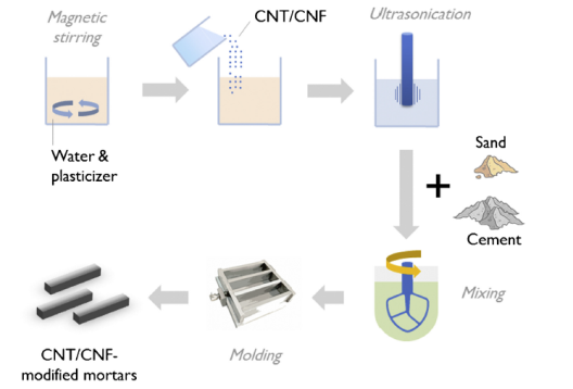
Figure 1: Schematic representation of the nano-modifield mortars manufacturing process [5]
In addition fig. 2 depicts the as-processed state of MWCNT-reinforced concrete specimens with varying tube loadings. The bottom row depicts reference specimens, whereas the top and middle rows show specimens with tube loadings of 0.6 and 0.2 wt% of cement, respectively, wherein porosity appears to increase with nano-reinforcement concentration.
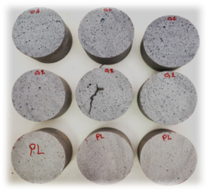
Figure 2: Various amounts of carbon nanotube loadings inside cement matrix: 0.6 wt% of cement (top row), 0.2 wt% of cement (middle row) and plain cement (bottom row)
2.2 Acoustic Emission Monitoring
Large concrete structures like buildings, storage tanks, bridges, dams, offshore structures, flyovers require reliable non-destructive testing methods for assessing structure integrity. Acoustic emission is a widely used technique for monitoring concrete structures, and is based on the phenomenon of the rapid release of energy from different localized sources inside a material generating elastic waves [23]. Such stress waves propagate through the solid due to energy released during the deformation process and the amount of acoustic energy released depends on the size, the speed of the local deformation process and the material. AE can detect lesions such as crack growth, fracture growth, monitoring deformations, corrosion etc. in a wide range of materials. The transducers are usually piezoelectric and transform the energy of the transient elastic wave to an electric waveform which is digitized and stored. The AE sensors record the accumulated activity which is indicative of the severity of cracking. Certain indices based on the magnitude or the number of the AE signals has been employed successfully in the health monitoring of heterogeneous structural materials like concrete and composites. In addition, when multiple sensors are applied, apart from the number of AE hits, it is possible to be found the source of events because of the time delay between the acquisitions of the corresponding signals at different sensors. This allows the estimation of which part of the material needs repair, which is of paramount importance for large-scale structures. Also via AE the material’s mode of fracture can be studied and characterized [24-26].
However, there are other important aspects of the AE testing, which are based on the qualitative parameters of the received signals. It has been seen that the shape of the waveform is indicative of the fracture type, something very important for the classification of cracks in different materials. Shear cracks follow tensile cracks as damage is being accumulated within the material. Therefore, the characterization of the cracking mode can act as a warning against final failure. It has been shown that tensile events are linked to higher frequency content and higher RA value, fig. 3, than shear [27-30]. This is mainly due to the larger part of energy transmitted in the form of shear waves, which are slower; therefore, the maximum peak of the waveform delays considerably compared to the onset of the initial longitudinal arrivals, This kind of classification has proven useful in laboratory conditions concerning corrosion cracking in concrete, fracture of cross-ply laminates, as well as discrimination between tensile matrix cracking and fiber pull-out during bending of steel-fiber reinforced concrete [31, 32]. In fig. 3 and in fig. 4 is given a typical AE signal and a typical AE signal due to different types of fracture respectively.
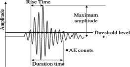
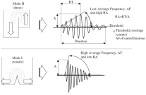
Figure 3: Typical AE signal and parameters Figure 4: Typical AE signals due to different types of fracture
2.3 Mechanical performance
Determination of the fracture toughness by means of three-point bend tests on notched beams
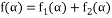
In the present study for calculation of the critical fracture toughness of cementitious materials used the Hilleborg’s [33] crack model of concrete which is similar with Dugdale-Barenblatt crack model of metals. For cementitious composite materials, such as mortar or concrete, the fracture toughness is determined using linear elastic fracture mechanics (LEFM) considerations. The P-CMOD response is obtained from notched beams, subjected to the center-point loading conï¬guration shown in fig. 5. The tests are performed under CMOD control, where this parameter is measured using a clip gage mounted on knife-edges. The thickness of the knife-edges, d, is taken into account in the calculations.
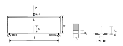
Figure 5: Three-point bend test configuration for notched beam specimen
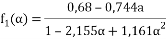
For this geometry, the stress intensity factor (KI) is given by
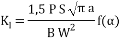
where P is the applied load, a is the crack length and α = a / W is the relative crack length (with S=3W and αo=ao/W=0,25). The geometry dependent function, f(α) is determined using two-dimensional plane stress analysis and is given by
Where
 when
when 
 when
when 
Also, in a similar way,
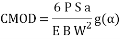
where the dimensionless geometry-dependent function, g(α), is given by
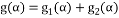
Where
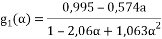
 when
when
 when
when
As it is evident from fig. 1, the CMOD is not measured exactly at the notch mouth but at a distance d, which must be taken into account for determining the real value of CMOD from that measured in the test (denoted as CMODMesured).
Therefore, 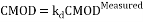
The conversion factor kd can be determined, for 1 mm  d 6 mm, from
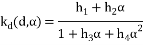
The coefficients used to compute kd for the CMOD correction are given in table 2 for different knife-edge thicknesses.
Table 2: Coefficients used to compute kd for the CMOD correction
|
d(mm) |
h1 |
h2 |
h3 |
h4 |
|
1 |
0.0050 |
275.1 |
275.9 |
0.0399 |
|
2 |
0.1508 |
162.5 |
163.6 |
0.0118 |
|
3 |
0.1037 |
104.1 |
105.1 |
0.01631 |
|
4 |
0.0777 |
76.2 |
77.2 |
0.0137 |
|
5 |
0.0623 |
60.2 |
61.1 |
0.0117 |
|
6 |
0.0521 |
49.7 |
50.6 |
0.0106 |
For large α (> 0,4) the correction is insignificant, hence for specimens with relative notch lengths in the order of 0,4, no correction needs to be applied. Moreover, for thin knife-edges (d < 2 mm) the correction is always negligible.
Determination of the fracture energy by means of three-point bend tests on notched beams
The fracture energy is defined as the amount of energy necessary to create one unit area of a crack. The area of a crack is defined as the projected area on a plane parallel to the main crack direction. This test method is not recommended for fiber-reinforced concrete. The fracture energy is determined by the equation,
 [N/m (J/
 ]
]
Where, Wo (Nm), is the area under the load-deformation curve shown in fig. 6
 (kg) ;
m1 = weight of the beam between the supports, calculated as the beam weight multiplied by S/L (fig. 1).
The length L of the beam as well as the span S during the test must be measured with an accuracy of at least 1 mm;
m2 = weigth of the part of the loading device touching the beam which is not attached to the testing machine, but follows the beam until fracture;
g = acceleration due to gravity (9,81 m/s2);
δo = deformation of the beam at fracture (m), as shown in fig. 2;
Alig = area of the ligament (m2), defined as the projection of the fracture zone on a plane perpendicular to the beam axis.
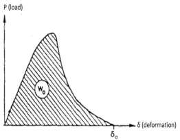
Figure 6: Load-deformation (CMOD) curve
Test procedure for fracture energy measurement
The test is performed with an approximately constant rate of deformation, which is chosen so that the maximum load is reached within about 30-60 seconds after the start of the test. The deformation of the center of the beam and the corresponding load are registered until the beam is completely separated into two halves. In case the deformation is not measured directly on the specimen it is recommended that before measuring the load-deformation curve the load is cycled 3 times between 5% and 25% of the expected maximum load. The load should be measured with an accuracy of at least 2% of the maximum value in the test. The deformation must be measured with an accuracy of at least 0.01 mm. Finally, the Crack Mouth Opening Displacement (CMOD) will be monitored during the test performed with controlled load in a closed-loop testing machine. The load will be applied at a rate between 2 and 3 N/s. A plot of CMOD versus applied load will be produced. Mechanical characterization under three point bending testing was performed on an Instron 5967 testing frame (Instron, Norwood, MA, USA) equipped with a 30kN loadcell. For the accurate recording of displacement C.M.O.D were used a Crack Opening Displacement (COD) Gauge extensometer with gauge length 10mm by Instron company.
3. Results and Discussion
The effect of CNT presence and concentration to the flexural and compressive strength has investigated in previous study. The researchers were observed that subjection of the suspension to the vacuum-assisted air removal procedure significantly enhanced the material’s flexural strength, compared to non-vacuumed suspensions. The maximum improvement in flexural strength, compared to the control specimens for vacuumed suspensions, appeared at 0.4 wt% MWCNT loading and was approximately 17% improvement at 0.2, 0.6 and 0.8 wt% loadings were 12, 10 and 9% respectively [4]. In the present study, the fracture energy of vacuum and non-vacuume nanocomposite mortar, Gf, as the way the fracture energy effects on the acoustic emission energy are investigated. In respect to the flexural strength the researcher observed that the specimens had the similar behavior as shown in table 3. The flexural strength calculated by using the following equation, where L, B, W and a0 are specimens dimensions presenting in fig. 5.
σ = 
Table 3: Comparison results of Flexural strength between specimens with and without notch.
|
Flexural Strength |
Flexural Strength with notch |
|||
|
CNT loading, |
Non-Vacuumed |
Vacuumed |
Non-Vacuumed |
Vacuumed |
|
0 (plain) |
5.36 ± 0.38 |
5.43 ± 0.23 |
5.72 ± 0.21 |
5.64 ± 0.25 |
|
0.2 |
4.15 ± 0.28 |
6.09 ± 0.43 |
4.73 ± 0.22 |
5.98 ± 0.11 |
|
0.4 |
4.61 ± 0.48 |
6.34 ± 0.67 |
5.00 ± 0.34 |
6.74 ± 0.13 |
|
0.6 |
4.97 ± 0.36 |
6.01 ± 0.66 |
4.83 ± 0.33 |
6.12 ± 0.31 |
|
0.8 |
4.78 ± 0.21 |
5.92 ± 0.5 |
4.87 ± 0.28 |
6.35 ± 0.39 |
It is widely known that CNTs increase the mechanical properties. Table 4 shows the results of effect of CNTs to the fracture energy, Gf, for vacuumed and non-vacuumed specimens. It is clearly that CNTs increase the fracture energy and the maximum value appears in the rate of 0.4% wt. cement CNTs. Above the rate of 0.4% there were reduction in the fracture energy however the values of Gf continues are higher than control specimens. In addition, all non-vacuumed specimens showed slightly elevated values than the control specimens but lower for vacuumed specimens because of porosity which is created because of CNTs.
Table 4: Comparison results of Fracture energy between Vacuumed and Non-Vacuumed suspensions
|
Fracture Energy [N/m (J/m2)] |
||
|
CNT loading, |
Non-Vacuumed |
Vacuumed |
|
0 (plain) |
1.1655 ± 0.063 |
1.1281 ± 0.060 |
|
0.2 |
1.1681 ± 0.122 |
2.0338 ± 0.086 |
|
0.4 |
1.6910 ± 0.115 |
6.5373 ± 0.369 |
|
0.6 |
2.1460 ± 0.050 |
2.9987 ± 0.383 |
|
0.8 |
1.8185 ± 0.200 |
2.4623 ± 0.165 |
Except for plain specimens which had similar fracture energy, the fracture energy of the specimens which had been in vacuum was increased. Gf of the nanocomposite with 0.2% and 0.4% wt. cement CNTs was found to be higher at about 80% and 479% respectively related to control specimens while for 0.6% and 0.8% wt. cement CNTs was found an increment at about 166% and 118% respectively. On the other hand, non-vacuumed nanocomposite specimens with 0.2% wt. cement CNTs were found it that had limited growth about only 0.2%. Greater increase of approximately 45%, 84% and 56% showed the nanocomposites specimens with 0.4 %, 0.6% and 0.4% wt. cement CNTs respectively. Comparing the two types of mixtures, vacuumed and non-vacuumed, the results showed that the fracture energy increment for all rates for vacuumed specimens. Specifically, for the rates 0.2% and 0.4% wt. cement CNTs the increments were about 74% and 287% respectively while for 0.6% and 0.8% wt. the increments were only 40% and 36% respectively. The entire above are shown in fig. 7. Finally, fig. 8 shows a typical load-CMOD graph for all rates, 0% up to 0.8% wt. cement CNTs, of vacuumed nanocomposite specimens and non-vacuumed specimens.
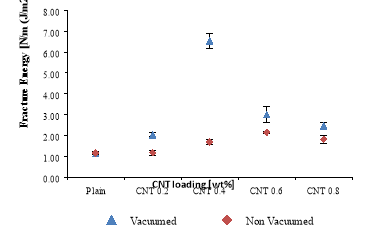
Figure 7: Diagram of Fracture Energy, Gf, results


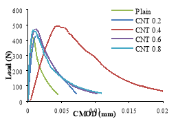
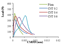
Figure 8: Typical load-CMOD curve for all rates of nanocomposite specimens for a) vacuumed and b) non-vacuumed are presented.
For Acoustic Emission (AE) monitoring in real time under three point bending tests of CNT-reinforced concrete specimens two R15a AE sensors were used, with broadband response ranging from 50 to 400 kHz and a maximum sensitivity at 150 kHz, attached on the lower section of the specimen. The R15a is a narrow band resonant sensor with a high sensitiv
Cite This Work
To export a reference to this article please select a referencing stye below:
Related Services
View all


DMCA / Removal Request
If you are the original writer of this essay and no longer wish to have your work published on UKEssays.com then please click the following link to email our support team:
Request essay removal