Industrial Automatic Drilling Machine
| ✅ Paper Type: Free Essay | ✅ Subject: Engineering |
| ✅ Wordcount: 1031 words | ✅ Published: 18 May 2020 |
Introduction
In this scenario, advancement of technology changes the method of production from manual to automation. In fact, automation plays essential role for the product quality and production efficiency. There for, in this project I’m going to introduce a drilling robot how it drills into the spur gears at a gear Production Company.
Project Background
In this project I’m going to use spur gears, which are drilled by the drilling robot at the center of it. In order to developed such a system first of all, I had to design a system in machine simulation by using some components like drilling robot, conveyor belt, couple of photocells and so on. Secondly, basis on the simulation I developed a ladder logic, and the perfect combination of both designs gave me desirable outcome.
Problem Statement
In this project it is difficult to design a ladder logic program according to the design of machine simulation. If we missed one output, all the system may not work. Hence it is very important to develop error free ladder program to simulate and runs the system. Apart from this, final product packaging was also troublesome issue but by we all know that trial and error is a key of success, and which is exactly happed we me and at the end I got solution.
Project Objectives
- Development of machine simulation design in the machine simulation3 by using robot conveyors, photocells, pushbuttons, and couple of pushers.
- Gives appropriate inputs/outputs and commands to each and every component, which we used in the machine simulation.
- Design the ladder logic program of simulation design in the EasyPLC and connect it with the simulation design.
Methodology
Description of selection project
With a view to show a working of robot and conveyors in the production department I select it.
- PLC: in this project I used EasyPLC software for ladder diagram. For the ladder design I used timer, counter, conditions, close/open loops and set/reset coils.
- Working: it works on the basis of given and output and for that we can different types of programming languages but I used ladder logic for this project.
- Application: Before development of any automation system we should use to design all the system and programing
Robot
I used a drill robot for this project; it drills the spur gears by doing drill arm up and down. It is a kind type of Polar robot also know as spherical robots. Its arm connected at the base with joints like twisting. (RobotWorx, 2014)
Project Design
The system starts by pressing start button, which on the work part creator followed by pusher arms, photocells, drill robot, conveyors and ended at storage system. Which is given in the figure below.
Selection system parameters
For this system I used pneumatic arm for pushing spur gears to the drill station and conveyor, secondly I used photocells to active pusher arm at the presence of the gear. I used timer for drill work, and counter for work part count. Besides these, I select conveyors for the gear transport through the storage.
Project working principles
In the industry this system automatically drills the spur gears at proper center and works effectively. 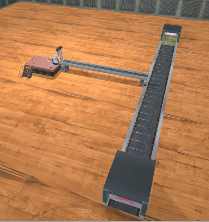
Figure 1 drilling system
In the given figure we can see that left hand side system produce the spur gear and from the top a box comes at T-section, where counter will center the number gear and let the box run after 12 gears. While at the bottom it storages.
Results and Discussions
Variables
For the automation of my system I used following variables with appropriate outputs, inputs, counter, timer, set/reset coils and open/close contacts.

Table 1 Variables
Ladder program
Start Stop
For the staring of the system I used one close contact with input that allows starting the work. For the stop I used open contact with start button to stop the system. Finally, once the working start it allows to produce work parts (Spur gear).

Figure 2 start/stop conveyors
Release New Gear
Once the system detects box, and pusher 1 back, it creates new work part (Spur gear).
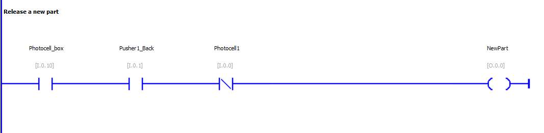
Figure 3 Release new Gear
Pusher 1
Presence of the new work part is input for pushers one, so once it detects gear by photocell push it to the drill station. And second network I used for move back position of pusher 1, by adding some open contact cell with drill worked variables.
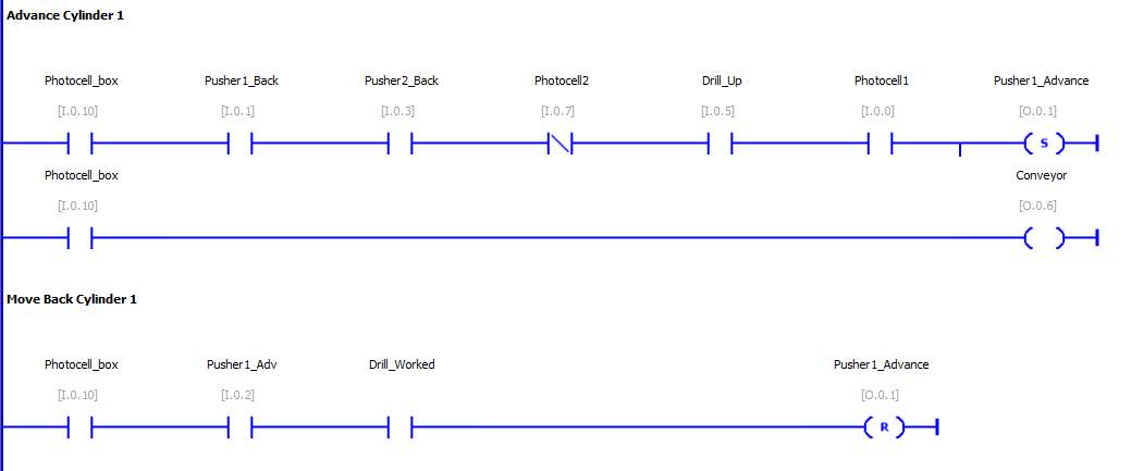
Figure 4 Control system of pusher 1
Drilling robot
Controlling is not a big deal if use separate it works in small portions and try to fix it step by step, so I did exactly the same. For this program firstly I developed individual working and later merged them together and give signal command. So this portion starts with pusher 1 advance drill starts working, secondly, it moves down with set coils. Where, the drill works for a couple of seconds.
Furthermore, I by the third network drill stop working and move up at ideal position. Forth network shows conditions of the timer. Finally the last network is a trump card of PLC like it has to modify the work part after all process without it we cannot complete the simulation. For it I used combines output like once the drill start working modifier change the work part and we get final work part.
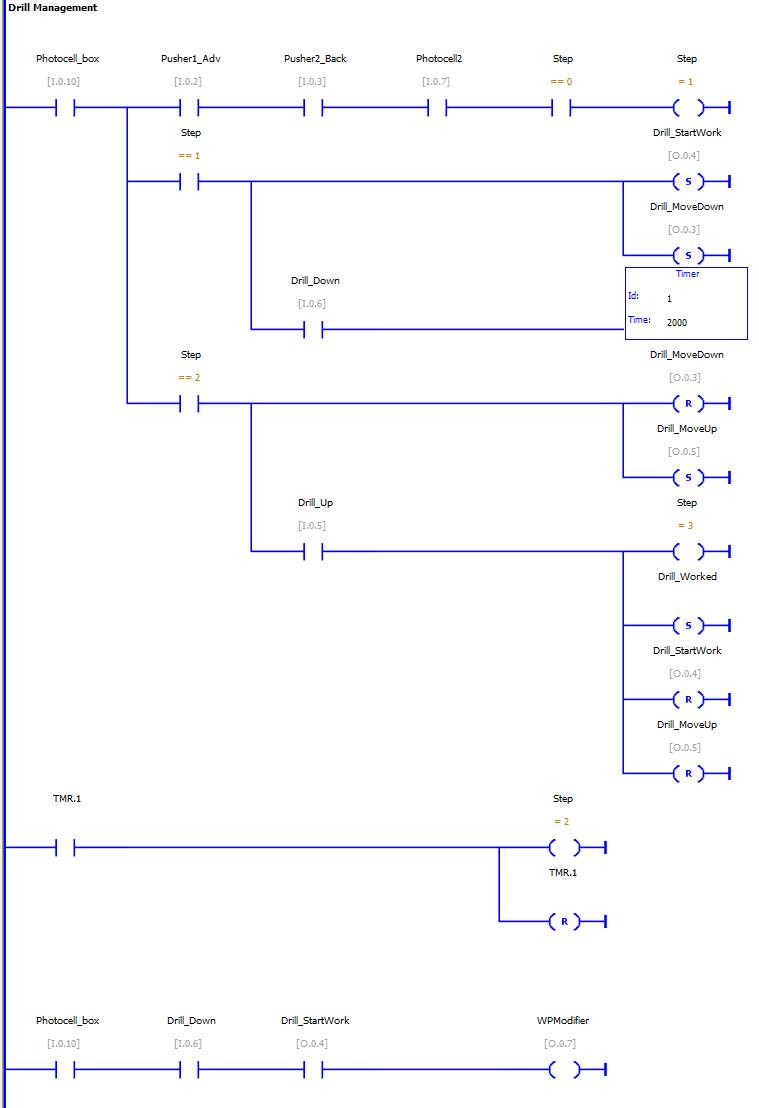
Figure 5 Control system of drilling robot
Pusher2
Once the gear being drilled by the drilling robot, it actives and push it to the conveyor. For this system I had to use a sequence of close contacts like pusher 1 back, drill work, phocell2, drill up with set coil output. And also I used another set coin for conveyor, which starts with the pusher 2-advance command.

Figure 6 Network diagram of pusher 2
Product Packaging
Following system 1, I used for the counting of the gears once it counts 12 pic it detect to the main conveyor and let it to run the main conveyor. Another network verify the presence of 12 gears and let them to the storage room.

Figure 7 programming of packaging
Bibliography
- RobotWorx. (2014, jan). What Are The Main Types Of Robots? Retrieved from www.robots.com: https://www.robots.com/faq/what-are-the-main-types-of-robots
Cite This Work
To export a reference to this article please select a referencing stye below:
Related Services
View all


DMCA / Removal Request
If you are the original writer of this essay and no longer wish to have your work published on UKEssays.com then please click the following link to email our support team:
Request essay removal