Implementation of Solar Tracking System Using RTC
| ✅ Paper Type: Free Essay | ✅ Subject: Engineering |
| ✅ Wordcount: 1309 words | ✅ Published: 31 Aug 2017 |
ABSTRACT:
The main objective of this project is to track the solar energy efficiently and using the same for the house hold applications like glowing Small Bulb, Mobile Phone Charging etc., Commercial made solar trackers to any solar panel array help in increasing the time of the panels facing the sun and allow them to produce their maximum power. Unfortunately they can be expensive to buy. We decided to make our own solar tracker to see if we could reduce the cost. We did not want to re- invent the wheel but wanted to make it more affordable. We started out small and came up with the idea of solar tracking using time instead of using a device that would sense where the sun is and moving the panel towards it. The objective of this project is to control the position of a solar panel in accordance with the motion of sun. Thus our objective is efficient utilization of the solar energy for development of nation and clean environment.
Key Words: Solar Tracker, RTC, LDR
I. INTRODUCTION:
Today, 70% of the population in Indian rural areas experience a dramatic situation where the electric supply is very low and irregular, and in some cases, completely absent from 80,000 villages in the country. The country suffers from unequal energy distribution, with power cuts of 2 to 3 hours in major cities, and in rural areas from 6 to 10 hours during the hot season (May to June). Up to 50% of households in India have no access to modern lighting and the electric grid did not reach remote places of the countryside, with some provinces lacking electricity in the 95% of the region.
There are some solutions like solar electricity from solar panels. Although many assume that renewable energy is too expensive for the poor but if it is combined with affordable financing mechanisms, it can be fully implemented and makes this type of clean electricity (and many others like portable rechargeable lamps) a viable option for millions in India. Both renewable and non renewable resources are being used for production of electricity to meet the needs. But non renewable resources are under the stage of extinction so it is better to choose the renewable resources.
II. EXISTING SYSTEM:
The simplest of all uses an LDR – a Light Dependent Resistor to detect light intensity changes on the surface of the resistor. Other methods use two phototransistors covered with a small plate to act as a shield to sunlight, as shown in Fig. 2. When morning arrives, the tracker is in state A from the previous day. The left phototransistor is turned on, causing a signal to turn the motor continuously until the shadow from the plate returns the tracker to state B. As the day slowly progresses, state C is reached shortly, turning on the right phototransistor. The motor turns until state B is reached again, and the cycle continues until the end of the day or until the minimum detectable light level is reached.
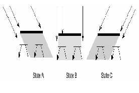
Fig.1: Principle of operation of an LDR
The problem with a design like this is that phototransistors have a narrow range of sensitivity, once they have been set up in a circuit under set bias conditions It was because of this fact that solar cells themselves were chosen to be the sensing devices. They provide an excellent mechanism in light intensity detection making use of renewable energy (solar energy) to produce power. The same energy which is generated further used mobile phone charging, household applications such as glowing small bulb etc., The diagram shows the overview of our project, when the system is on Real Time Clock gives the auto update of Time, date to microcontroller, this information is displayed on LCD through microcontroller. According to the time provided by RTC stepper motor will rotates with particular angle to change the position of solar panel to absorb solar energy. The energy absorbed by solar panel will charge battery, From battery it is given to mobile phone charging circuit which is further used to charge the mobile phone. At the same time the energy stored in the battery used by power circuitry for glowing small lamp etc.,
FUNCTIONAL BLOCK DIAGRAM:
because they are sensitive to varying light and provide a near linear voltage range that can be used to an advantage in determining the present declination or angle to the sun. As a result, a simple time operated solar tracking system using RTC based control system is proposed, with the tilt times of a panel position with respect to natural position of the Sun has been
RTC DS1307
MICRO CONTROLLER
AT89S52
MECHANICAL ROTATING UNIT
DISPLAY UNIT
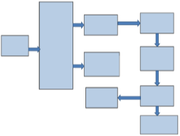 LCD 16X2
POWER SUPPLY
SOLAR PANEL
BATTERY CHARGING UNIT
BATTERY POWER
CIRCUITARY
implemented as an algorithm to controller.
III. PROPOSED SYSTEM
Now a day’s power problem is becoming big issue in society to minimize that we came up with this project. Here we are
Fig2: Block diagram of proposed solar tracking system.
The main components used are microcontroller (AT89S52), RTC (DS1307), ADC (MCP3201), Op-Amp (LM324N), 16X2
LCD, Voltage controller (7805). The solar panel, Battery, DC motors are connected externally. The solar panel used in our project is made up of poly-crystalline cells. For these cells aiming is not critical as the cells are picking up the light from many different angles.
IV. WORKING
The power supply is given to the tracking system from external battery.7805 voltage regulator converts this incoming power supply into 5 volts in order to provide supply to other components in the system. The program to the AT89S52 micro controller is given through ISP pins. Based on RTC , the number of tilts of the panel will be set manually using four switches that are fed as an inputs to the 74LS21 AND gate and its output as an interrupt to the controller. Real Time, Tilt time settings are displayed on LCD which is connected to Port 1 of the micro controller. In this project, we use 4 tilts for tracking purpose and 5th tilt for bringing the panel back to the initial position. The RTC continuously runs and sends a high output to the microcontroller at our prescribed tilt time. Then microcontroller sends a high output to the L293D driver which drives the DC motors connected to the panel. The panel rotation or tilt angles will be initially fixed in the program that is given to the microcontroller. The output of solar panel is connected to OpAmp which amplifies the signal and gives it to the ADC which is connected to the port 1 of the microcontroller. Voltage generated by the panel as per the individual tilt time is displayed on LCD. Display of LCD is shown in fig 6.
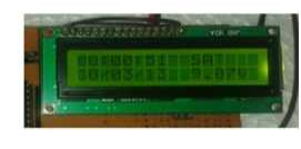 Fig 3: LCD displaying the time and date
LCD is used as the display unit. It stands for Liquid Crystal Display. These components are “specialized” for being used with the microcontroller. LCD screen consists of two lines with 16 characters each. Each character consists of 5x7dot matrix. Here we use LCD to display real time provided by RTC.
EXPERIMENTAL RESULTS:
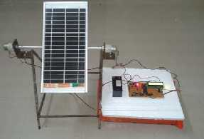
Fig 4: Prototype of Time operated solar tracking system using RTC

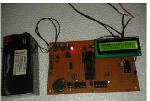 Fig 5: Control equipment of solar tracking system
CONCLUSION:
The design of microcontroller based on efficient solar tracking system with real time clock is developed and described. The proposed system provides a variable indication of their relative angle to the sun by comparing with pre defined measured readings. By using this method, the solar tracker was successfully maintained a solar array at a sufficiently perpendicular angle to the Sun. The power increase gained over a fixed horizontal array was in excess of 40%. The proposed design is achieved with low power consumption, high accuracy and low cost.
References:
Table 1: Captured Panel voltage with proposed
tracking system.
|
S.NO |
TIME |
PANELVOLTAGE (V) |
|
1 |
8.00 AM |
9.0 |
|
2 |
9.00 AM |
12.5 |
|
3 |
10.00 AM |
13.0 |
|
4 |
11.00 AM |
13.5 |
|
5 |
12.00 PM |
14.0 |
|
6 |
1.00 PM |
14.5 |
|
7 |
2.00 PM |
12.5 |
|
8 |
3.00 PM |
11.4 |
|
9 |
4.00 PM |
9.3 |
|
10 |
5.00 PM |
6.5 |
|
11 |
6.00 PM |
1.5 |
Table 2: Captured panel voltages without proposed tracking system
Cite This Work
To export a reference to this article please select a referencing stye below:
Related Services
View all


DMCA / Removal Request
If you are the original writer of this essay and no longer wish to have your work published on UKEssays.com then please click the following link to email our support team:
Request essay removal