GSM based Wireless Notice Board
| ✅ Paper Type: Free Essay | ✅ Subject: Engineering |
| ✅ Wordcount: 1756 words | ✅ Published: 30 Aug 2017 |
2.2 BACKGROUND
The use of scrolling display boards for advertisement is becoming common these days at various shops, shopping centers, railway and bus stations and other such places. It is becoming an effective mode for communicating with the public and providing them information. The issue with such displays is when frequent updating of the messages is required. It becomes inflexible, time consuming and a technician needs to go to that location of display board and plug the computer to it and then update it. it doesn’t give the flexibility to change the message from any remote place. Another issue is with the placement of display boards, it cannot be placed at any place due to its complex and delicate wiring.
2.3
To overcome such problems, I designed a GSM based Wireless LED notice board. It is basically a display system that uses real time noticing, b sending messages through mobile phone in the form of SMS. In such system, there is no requirement of reprogramming the code to update or change the message that needs to be updated as the whole process is based on wireless technology. A multiplexing method is used to drive the LEDs. And the power requirement for display module is also reduced.
2.4 OBJECTIVES
I aimed to develop a moving sign board which can be controlled by the user by sending a SMS. The user can change the scrolling/display message immediately unlike the old device which requires personal attention at the location using a desk bound device like PC or laptop. My project will let user update it even from a remote distance. Once the message is displayed and is in use, it gets deleted from the system memory to allow new updates to be stored and making space for upcoming SMS. Also, I wanted to design a model which has reduced complexity and simplified hardware and wiring requirements.
2.5
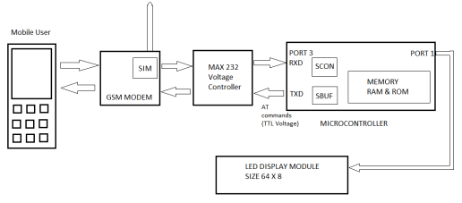
Wireless technology is an upcoming technology, due to this reason I planned a project based on it. It implements the wireless communication between a mobile phone and a display board. It uses a combined feature of microcontroller and wireless technology to construct an accurate and effective communication system. The user makes use of a simple GSM based mobile handset which will help in sending messages for display purpose via SMS to various display boards. A GSM modem is used at the receiver end which detects and receives upcoming new messages. Proper coding is set in the microcontroller which gives AT commands to read the SMS that is received from the modem and is then stored in the microcontroller.
2.6
The nature of my project initially was research and survey based along with problem solving. I had to consider the safety issue and fast track transmission of the information. The duties I was required to perform are:
- I had to divide the project in smaller parts and assign time-duration for each task.
- I was involved in intensive research and analysis based on the topic of interest for my project. I had to perform survey on various microcontrollers, peripheral devices for e.g. LCD, transmitter and receiver circuits, GSM and many more based on the need of the project.
- I projected a schematic diagram with the help of ORCAD software.
- I designed the PCB layout.
- After having the PCB layout I was required to make the hardware structure.
- Which was followed by writing the code for the working of the device.
- Lastly, it involved preparation of report and presentation for the entire project.
- It was my duty to keep my project guide updated with the progress of the project.
2.7 PROFESSIONAL ENGINEERING ACTIVITY
To begin working on my project, I started studying topics of interest and related to my project. After processing and analyzing the information found based on my survey, I started designing the block diagram for my project. I used ORCAD software to design the schematic diagram. It was a new software for me, so it took time in understanding its functions and tools. I structured my drawing in such a way that the project focuses on the transmission of textual data through air interface with the help of GSM through asynchronous serial communication. When a unique pass key is entered, the data gets displayed on the LCD. Also, it will receive and accept data from dedicated and registered user only by performing address matching.
2.8
Various components that were used are described below:
- Power supply – I used a step-down transformer of 230V primary to 5V secondary voltage that would give a power supply of +5V. This circuit also provides a variable 12V supply to the motor drivers.
- GSM Modem – in the receiving section, it consists of a slot which holds the SIM card. The SIM stores the messages that are sent by the user. It works on single supply voltage of 3.4V – 4.5V.
- Max232 level convertor – it is a dual driver or receiver which acts as an interface medium between the microcontroller and the modem.
- Microcontroller – I used the 89S52 microcontroller which is a 40-pin powerful controller which consists of several features. It provides a special feature of data signal and clock signal which is required for scrolling the messages.
- 64×8 LED dot matrix – it is formed by wiring multiple LEDs together in rows and columns. It is done so that it minimizes the number of pins that are required to drive them. Each character is displayed by scanning of either rows or columns.
- Shift register IC74LS154 – it is a high speed 8bit Serial-In Parallel-Out shift register. I have made use of shift register to minimize the number of I/O pins that would be used to drive the column of LED matrix.
- Crystal 11.0592MHz – such high value crystal helps in reducing the flickering effect that is seen in the LEDs.
2.9
After finalizing the components, I went ahead to connect each component to the PCB. After laying out the PCB me and was shown to my project guide for any improvement possibility and to get feedback on it. After getting the final confirmation from my supervisor I connected the components and completed the full hardware structure. The next task was writing the code for its functioning. I prepared a flow chart to follow a well-defined path while writing the code. I used keil Microvision software to write my code. It develops a HEX file which can be loaded into the microcontroller. I wrote my programming code in Embedded C language. I divided my working in two parts, so the code was written in two parts.
2.10
The display process begins by writing ‘0’ on all rows. This will result in blanking out of all LEDs at the beginning. The microcontroller uses ASCII code for each character that must be displayed. It uses this value to access the corresponding display pattern in a character look up table. The display will be sent out to the display shift register in serial manner. For but with value ‘1’, the LED will be kept off and for bit with value ‘0’, the LED will be kept on. This process gets repeated for first line of the other five display matrix. And thus, enabling the first pin. The same process is repeated for every row till all the rows are displayed. In row scanning, appropriate logic levels are set and passed to the columns and each row is selected for about 1ms time. Thus, creating a persistence of vision effect and the image is displayed as a still perceived image. The microcontroller uses and generated a HEX value for every character that needs to be displayed.

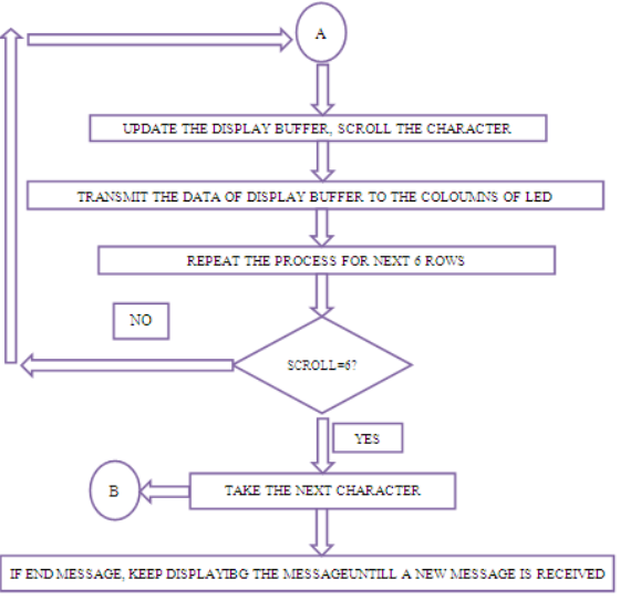
2.11
The second part involves scrolling of the message. This effect is achieved by defining seven display buffers, each of size 32 bits and stores the bit information of 64×8 LED in the matrix. The scrolling process for displaying the message begins from right to left. All the column values for all the rows are shifted to the left direction by giving a suitable volume of shift step. This will help to move the character from right to left. After successfully shifting of the character, the row values of next character are taken up. This is done after scrolling it for 5 time per character to accommodate many characters simultaneously. For every shift, the display buffer gets updated. Every character is shifted six times to fully load into the display buffer. Thus, the process continues until all the characters in the messages are loaded. After loading of each character, the message will continue to scroll until a new message is received. The microcontroller automatically stops the display and extracts the new message from SIM card on the arrival of new message. It then executes the above cycle for new display process which scrolls down the new message.
2.12
On completion of the software and hardware part of my project, I performed a test run on it to check the working of the project. On facing difficulties, I performed troubleshooting on the whole system and gave it a run again. Constant helped was received by my faculty members during any difficulty. Major problem faced by me was in completing the programming code of the model. As my project’s main heart was the software. I referred many software books and coding languages to understand the problem and solve it. Another issue was related to the receiving the signal from the GSM module to the microcontroller. I thought the problem was in the GSM module, but on later evaluation of the problem, I came to know the problem was in the connection, the input pins for the microcontroller was mismatched and soldered in wrong place. To rectify the issue, I studied my circuit diagram again and soldered it to the correct place.
2.13 SUMMARY
To conclude, my project explains each development step I took for designing the GSM based notice board by integrating features of all hardware components used. Each module is reasoned out and placed carefully, thus making the unit to work best. The speed of the display can be controlled through the software and the message is displayed as required. Keeping a good scope open for future use in various industries such as food industry, in trains, in educational institute etc. The project gave me a good experience in my own field. I developed many technical skills, managerial skills, and problem solving skills. I believe I made a good use of my academic knowledge that I had gained during my bachelor’s and applied it to my project. The project was successfully completed on time. I gave weekly report and presentation to the project guide.
Cite This Work
To export a reference to this article please select a referencing stye below:
Related Services
View all


DMCA / Removal Request
If you are the original writer of this essay and no longer wish to have your work published on UKEssays.com then please click the following link to email our support team:
Request essay removal