Fault Detection Robot for Underground and Overhead Cables
| ✅ Paper Type: Free Essay | ✅ Subject: Engineering |
| ✅ Wordcount: 1722 words | ✅ Published: 30 Aug 2017 |
CAREER EPISODE – 1
1.1 INTRODUCTION
During my journey of engineering, I completed a project named ‘Fault Detection Robot for Underground and Overhead Cables’. It was completed in my 6th semester while pursuing Bachelor of Technology in electronics and communication engineering from Guru Nanak Dev University, Gurdaspur, India. It was performed under the guidance of Prof. Anu Sheetal. The entire project was completed in six months from January 2012 to May 2012. Thus, my very first career episode is based on this project performed by me.
1.2 BACKGROUND
Normally most of the companies prefer to lay wires through underground. Wires are laid underground for various purposes. The reason for doing this is to protect the wires from any climatic conditions and changes. But while considering this positive factor there are cons of this method too. There occur problems while laying wires and during service and maintenance it becomes very costly, time consuming and difficult to fix and solve the issue. Also, cable can break due to any reason then it gets difficult to locate them and replace it. Basically, in manual technique of replacing cables, approximate location I found and the cables are dug out and manual checking is done to find the exact point of problem.
1.3
To overcome such challenges, I have designed a robot which can find faults and the place of complaint, making it easy for engineers and technicians to dig a hole at the precise place for error solving and fixation. The technology used behind the working of such robot is electromagnetic theory for detecting the discontinuity of the cable wires. Induced magnetic field is generated when a low frequency based signal can pass through the wire with the help of signal injector, which helps in finding the place of possible defect. The robot can locate the position of the fault or short-circuit issue from external surface and point out the exact place of discontinuity.
1.4 OBJECTIVES
The main idea and goal behind employing such project is to benefit the industries laying wires underground for various electronics, electrical or other purpose. In this project an overhead wire fault detection and location system is introduced as the main or fundamental for industrially controlled computers. The project was executed to overcome the problem to repair faulty wires which required the help of experienced and practical trained operators. The accuracy and precision of short circuit fault detection is improved and upgraded by using the combinations of different methods like current rate of change and zero detection are used, along with using different and new technology based hardware and software. Features like 5th harmonic current and ground phase voltage drop was integrated to it. The project was used and put to operation and it worked in good running condition.
1.5 MY WORK DUTIES
To implement and achieve success in this project, I started planning on how to approach the problem statement and what could be the possible solution for it. which followed by initial understanding on the working principle of the project. After making a work flow on the approach, I decided upon the components that were required for its implementation. A budget was made and followed all the time and a safety level was maintained during the progress of the project. Later staged involved in planning and designing of the PCB layout based on the block diagrams and the circuit diagram. Coding was done for the working of the project which was followed by performing certain tests and troubleshooting the whole device to find any faults and resolve them on time. The last stage involved preparation of the presentation and reports. My duties also involved meeting the supervisor weekly and updating her about my project progress.
1.6 PERSONAL ENGINEERING ACTIVITY
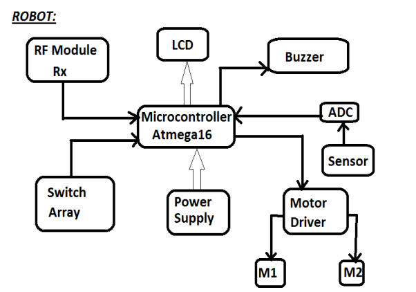
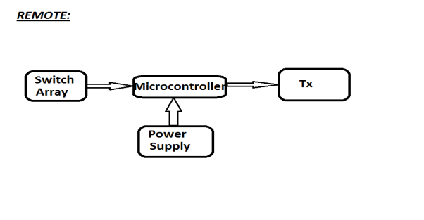
The execution part for my project began with outlining and understanding of all possible differences amongst industrial robots, service robots and their process of application or working. Along with that I also analyzed the challenges that are faced due to its application and different methods that could be employed to detect the fault and isolate the faults. I also included few examples for comparison of methods relating the situation. Based on their experimental results, I came up with my block diagram for the project. It has two parts one for the robot and other about the remote.
1.7
After finalizing my initial block diagram, I listed out the components that were required for the hardware structure of the robot and the remote. The components used are described below:
1. For Power Supply – Diodes of 1N4007, Capacitors of 1000 and 100 µf, IC7805, LEDs, Resistors, Push Buttons. Using these components, a power supply consisting of three parts namely, the rectifier unit, filter unit and regulator unit is designed for giving supply to my device.
2. LCD 16×2 – for displaying the location of faults by displaying a message or small written signal
3. Tx IC – HT12E
4. Transformer – 0-12V and 500mA
5. Motor driver IC – L293D
6. RxIC – HT12E
7. Buzzer – for alerting on finding a fault in the wiring
8. Transistor – BC547
9. Motor – 60rpm, to drive the robot
10. Microcontroller – ATMEGA16, the coding and the program is written and loaded into it for the functioning and signaling of the robot.
11. Magnetic field sensor – ZMY20, extremely sensitive sensor which is used for measurement of magnetic field or detection of magnetic ports. It has magneto-resistive effect of thin film perm alloy.
1.8
With the help of above components, I started to design and implement my hardware. I started with designing the power supply and then the robot. After completing the structure for the robot, I made a remote to operate it from a distance with the help of IR radiations. Once my whole device/robot was ready, I mapped a flow chart which described the working and the functioning of the device. The flow chart took lot of efforts as every small point had to be noted for the functioning of the robot. The flowchart can be seen below.


1.9
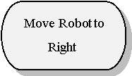
The core idea behind this robot was for short circuit detection that occur in the underground cable breaks. The continuity of the cables is first checked using a multimeter as the cables are laid across large areas. After detecting the stretch of wire where the problem of discontinuity occurs, the robot is made to use for detecting the final and precise location of the breakage or fault. External remote navigator circuit is used for the robot and it is placed on the cable. A wire is also connected to the signal generator unit. The robot is positioned in such a way that the discontinuity lies in the forward direction and the robot moves along that direction.
1.10
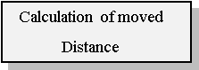
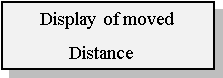
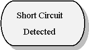
A 3KHz signal is passed through the wire and a power is supplied to the robotic unit. An electromagnetic field is generated as per the Faradays law, after the current starts receiving and moves around. This electromagnetic field will generate a voltage that will be provided using the microcontroller RA0 pin and thus controlling the movement of the robot. On reaching the point of discontinuity the robot will not generate electromagnetic field, which will trigger the buzzer circuit connected to it indicating the fault and location of the issue. The HALL sensor unit can be used and provided to get the exact distance that the robot moves in finding the discontinuity and the LCD module connected to it will display the details. Once the location of fault is found, the cable operators and technicians can dig that ground and resolve the problem easily.
1.11
Based on the working, I planned the flowchart for the coding and programming part of the circuit. I used the software called BASCOM-AVR which supports the 8051 microcontrollers and Ateml’s AVR microcontrollers. Both coding and testing can be performed using this software. I wrote a code for the below flow chart and successfully loaded it into the microcontroller to check it’s working. Robokits AVR USB programmer is used to load the program that is made in BASCOM into the microcontroller after generating a HEX file of the program. The best advantage of working on BASCOM is that it has menu options specially for troubleshooting your program.


1.12
After completing both hardware and software part for this robot, I gave it a test run to see its functioning. I faced an issue while running the robot, initially it didn’t detect or generate an electromagnetic field which was required to detect the faulty cables. So, I made use of magnetic read switch which could generate magnetic field of 440V or above and It was cheaper than the magnetic field sensors. On considering the safety perspective, there was a risk due to the use of high voltage of 440V. Thus, I decided to use a magnet to generate the require magnetic field and current instead of providing such high voltage supply. So, once the robot senses the magnetic field around the magnetic read switch that is generated with the help of magnet, the buzzer will start to work. Another issue was replacing this component i.e. to replace the magnetic sensor with a magnet because all the connections were done and the circuit could get complicated. To do that, it took lot of patience and it had to be done carefully. This was the major problem I encountered during my project.
1.13 SUMMARY
Thus, to save the manpower and wastage of time, I developed such robot that detects the faulty cables. I believe it will be helpful to various companies. The robot is designed to be user-friendly and easy to access. It is also cost-effective and controlling and maintenance is very easy. It has lot of scope for expansion, it can be used to detect faults at places which is not accessible by human hand or places which require large amount of safety.
1.14
This project was the first project of my bachelor’s degree, so it held lot of importance, and it taught me a lot. I gave a final presentation and a report document stating the work I did and the completed working and description of the project. I presented it to my faculty staff and in front of my classmates. I got good help and support from my guide in all difficult situations. It used my basic programming knowledge. It boosted my confidence in my field. I got motivated and inspired to implement and research new projects which would use more advance electronics and telecommunication knowledge.
Cite This Work
To export a reference to this article please select a referencing stye below:
Related Services
View all


DMCA / Removal Request
If you are the original writer of this essay and no longer wish to have your work published on UKEssays.com then please click the following link to email our support team:
Request essay removal