Examination of Solar Cell Reliability
| ✅ Paper Type: Free Essay | ✅ Subject: Engineering |
| ✅ Wordcount: 2511 words | ✅ Published: 18 May 2020 |
Abstract
Recently, solar-photovoltaic (PV) systems have significantly contributed to growing renewable sources of electricity all over the world. The contribution of Solar PV systems as a renewable energy source contributed 303 It contributed to 303 GW throughout the world at the end of 2016. It has thus attracted a lot of research in this energy as a lot of money is being invested in this technology. But this growth can be easily hampered if unexpected failures occur due to the long downtime periods. Hence RAM i.e., reliability, availability and maintainability assessment needs to be done for the solar-photovoltaic systems. The factors that affect the performance of PV module and the modes for the PV degradation are also discussed. The accelerated aging and PV module qualification standard tests are explained. The failure mode analysis of PV modules is also covered in the paper.
Keywords
Reliability, Availability, Maintainability, Solar-photovoltaic (PV) systems, Accelerated testing, Failure mode analysis degradation.
- Introduction
To establish some of the definitions upfront, we start out with either a film, if you are depositing a thin film material, which is usually divided into discrete devices using laser processing or we can start with a discrete wafer which has been processed into a cell. The module is combination of many of these cells. Cells can be tied up in series or parallel depending on what sort of voltage and current output we desire from the module. And finally, the modules combined to make an array. Modules require very little maintenance, typically 2-3 rinse per year. There are no moving parts in the module. They generally have a 20-30 years manufacturer warranty. A circuit module follows something very similar to the figure 1 shown below. For historical reasons, the crystalline silicon solar cell modules have typically had strings around 36 cells connected in series. This yields a maximum power point voltage in the range of 17-18 volts. This enables us to hit, even under lower light conditions, the overpotential needed to charge a rechargeable battery. There are various failure modes and degradation mechanisms which leads to reduction in power output or cause module failure. Most of these mechanisms are water ingress or temperature stress.
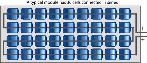
Fig 1. A circuit model of a solar cell. [1]
In the article [1] presented at the 27th european photovoltaic solar energy conference and exhibition, the PV standards, their qualification and testing and safety standards are discussed. The international standards set by PV module QA task force for the Internattional Electrotechnical commission (ICE) are mentioned. Further it concludes that the participation in such task force has significantly increased and the standards are being actively developed since then.
The paper [2] talks about RAM analysis of grid connected solar PV systems. It is a study of seven practical layouts of grid connected PV systems. The probability distriibution function for each of the faiure rate subsystems and subssemblies is calculated. Lognormal distribution is considered to be the best of the PDF of all the subassemblies. The expected lifetime is also caculated in this paper.
The paper [3] uses the RBD approach i.e., a reliability block diagram to find the system behaviour. Standard methodology to characterize the systems reliability and availability is described. The analysis is done for 5 year time period.The mean availability is predicted using the model. There are some insights on why the model differs from the reported results.
- Layouts of Solar-PV systems
The appropriate layout needs to be selected as the layouts have a considerable impact on the reliability. The selection depends on certain factors like control and operating capabalities, and the mode of operation. There are basically two modes of operation. Off-grid are which allows us to store solar power in batteries for later use and grid connected are the ones which can generate power only when the utility power grid is available. Below figure shows the classification of the solar PV systems. They are further classified by the grid-reliability level. They are grid connected with either insufficiently low reliability or sufficiently high reliability. The off-grid systems are classified into two main types of load carrying systems, they are deferrable loads and non-deferrable loads.

Fig 2. Types of Solar-PV systems [4]
Subsystems in Solar PV system and their subassemblies:
- PV array- Solar cell, Front glass, Encapsulate, Interconnect, Solder bond, Junction box
- BOS- Bypass diode, AC/DC switch, Grid protection, DC combiner, connector
- Inverter- AC/DC contactor, DC-link capacitor, Microcontroller, Cooling fans, PCB
- Storage- Battery, Control unit, charge controller
- Converter- DC-DC converter
Over 90% of the solar cell modules today are connected to the grid. As grid systems become more common, the importance has been shifted to matching the output of the solar module with whatever technology is being used to convert the DC power into AC power
Now, higher packing fraction enables lower glass encapsulant costs per watt peak. The lower packing fraction increases optical concentration. To put this module in a three-dimensional framework, we have the interconnected cells, the encapsulant above and below.
The basic layers responsible for generating the electricity are p-type and n-type layers. The solar cells are a system with multiple connections, components and layers. Back electrode layer, front grid, coating for anti-reflection, plastic or glass cover and encapsulant material are some of the common layers found in every cell. The number of layers can increase with the type. The reliability of some of the systems are interdependent of the reliability of its subsystems and component. The systems reliability is highly critical of components having high failure potential. RAM analysis aims to find the items with the highest critical impact to improve the overall reliability of the system.
- Tests for PV module
To achieve success in commercial field of PV, safety of the already deployed modules and the long-term reliability. Today most PV modules have a warranty of about 25 years and the maximum allowable degradation rate of 0.8% per year. What we are interested in finding out is that if the module that is being used will be able to have a service life of 25-30 years. IEC61215, IEC 616646, IEC 62108 are the certification/qualification standards for Crystalline Silicon module, thin film modules and CPV modules respectively. They help in finding out manufacturing design, materials and the flaws in the process which lead to premature field failures. The question needs to be asked if the qualification tests are enough for a 25-year lifetime. The answer is no.International PV Module QA Task Force operating with these 9 task groups.
1) Guideline for Manufacturing Consistency
2) Testing for thermal and mechanical fatigue
3) Testing for humidity, temperature, and voltage
4) Testing for diodes, shading and reverse bias
5) Testing for UV, temperature and humidity
6) Communication of PV QA ratings to the community
7) Wind Loading
8) Testing of Thin Film Modules
9) Testing of CPV Modules [1]
- Challenges in PV Reliability Studies
The predicted lifetime of PV modules is several decades. The investors find it risky to invest in a technology which could take up to decades for testing. It is rather not considered an option which takes decades in finding the failure modes and degradation analysis of the PV modules. Hence PV modules are subjected to accelerated aging tests which help in shortening the test time with the help of simulated test conditions. These tests are more severe than the actual field conditions at which the solar PV modules operate. To cut costs and keep up with the pace of the market, they need to be done with minimum sample size and the shortest testing times. Hence accelerated aging tests are developed. The basic equation for the expected number of forecast hours is described below.
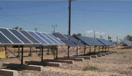
Fig 3. PV panels in field test [6]
The expected number of exposure hours E can be forecast as follows:
E = NKT/H
Where,
N = observed number of occurrences of a cell in a historical time period
H, K = data collection interval (in hours),
T = forecast time period.
- Accelerated Aging Testing
In such type of tests, the basic approach is to apply higher levels of stress than the actual conditions over short time period for failures to occur like when they are being used. Accelerated tests are used to shorten the test times using simulated conditions. Both, hard failures like reliability and soft losses like degradation can be induced on the PV module with AT. The accelerated aging tests for the solar-PV module are classified as:
- accelerated qualification testing (quality confidence- minimum),
- accelerated comparative testing (quality confidence- medium)
- accelerated lifetime testing (quality confidence- maximum)
In the above mentioned three types of aging tests, the first two are qualitative tests and accelerated lifetime test is a quantitative test. The qualitative tests, the prediction of life is not done but the focus is on finding the failures and the failure modes. Quantitative testing predicts the life of the module working on aspects like mean time to failure at certain conditions using some of the accelerated testing. [2]
|
Field failures |
Causes/Mechanisms |
Accelerated stress test |
|
Broken Interconnects |
Thermal expansion and contraction |
200 Thermal Cycles (TC200) Mechanical load (ML) |
|
Broken cells |
Mechanical stresses |
TC200 ML Hail |
|
Corrosion |
Moisture induced corrosion of cell metallization |
1000h Damp heat (DH1000) |
|
Delamination |
Adhesive bond sensitive to UV or contamination from the material |
DH1000 Humidity freeze 10 cycles (HF10) Ultra-violet (UV) |
|
Encapsulant discoloration |
Heat and UV |
UV |
|
Solder bond failures |
Stresses induced by thermal cycling or vibration |
TC 200 ML |
|
Hot spots |
Operating current > Isc |
Hot spot test (HS) |
|
Bypass diode failures |
HS Diode test |
|
|
Back sheet |
UV |
Table 1: Checklist of Design Failure Modes and Relevant Qualification/Safety Tests
The table 1 provides the information on major failure modes associated with crystalline silicon modules which include broken interconnects, broken cells, corrosion, delamination, discoloration of encapsulant, solder bond failures, broken glass, hot spots, ground fault, junction box and module connection failures, structural failures, bypass diode failures, and arcing. The causes associated to them are also listed. Most of the field failures can be found out with visual inspection. Broken cells, hot spots and bypass diode failures are the only few which require Electroluminescence (EL), Infra-red scan (IR), OC diode inspections with handheld device characterization testing respectively.

Fig 4. Graph of failure rates and the type of inspection required.
It shows that the humidity and the damp heat are the most commonly found reasons for failures.
- Failure mode and analysis
7.1 Determining the occurrence of the failure can be done in three steps:
- Each PV module should be inspected thoroughly for defects, then should go through its specific characterization test.
2. CNF/1000 or cumulative number of component failures per 1000 to the operating time of each failure mode

…… (1)
where operating time is in Years.
3. Occurrence or frequency ratings are assigned to each failure mode.
7.2 Failure/Degradation Mode
The failure modes lead to immediate warranty returns and degradation modes of PV module lead to power degradation towards warranty limit. are broken interconnects, solder bond failure, severe corrosions,

Fig 5. The maintenance data represents failure causes of solar PV from the year 2005-2014.
Fig 5. shows the analysis for the field failures. The solar PV module failure mode were observed. The tests done are on Crystalline silicon PV modules. It is observed that the encapsulant discoloration has the highest percentage of failure at 25%. While the hotspots account for lowest percentage of failures. The maintenance data represents failure causes of solar PV from the year 2005-2014. Studying various types of defects gives us an insight on which of the subassemblies fails their respective subsystem. The types of failures that occur are solder failure, encapsulant discoloration, back sheet detaching, hotspots, bypass diode failures, delamination and other few rarely seen failures. Below Fig 6. shows the defect in the module, the hot spot failure which affects the power generation capacity of the adjacent cells in the module. Fig 7. shows the delamination failure which occurs when the bond in the glass and the attached plastics begin to separate. This leads to moisture problems and lets the air between it, which causes corrosion and power failure.

Fig 6. Module Hot Spot Failure

Fig 7. Module Delamination Failure
Based on the subsystems in solar PV system and their subassemblies these defects can be correlated to the subsystem with which the subassembly belongs to.
7.3 The RAM analysis
The PV array subsystem is the subassembly with highest failure rate as encapsulate and solder bonds show the highest failure rates. So here we can say that it has the lowest reliability of all other subsystems in the PV system.
The connector subassembly has lowest repair rates among this subsystem.
The controller sees the highest failure rate in the storage subsystem hence it has the highest availability of all the subsystems.
The life of AC-DC inverter is low as it has high failure rate of all PV subassemblies.
The maintainability is highest for charge controller of storage subsystem and DC combiner of BOS subsystem. The connector has the lowest maintainability.
- Conclusion
The reliability for prediction of PV module lifetime in any environmental condition has always been a challenging task. The modules have gone through a dramatic change in 30 years and yet no methodical study on predicting the lifetime of solar PV modules have been carried out. To replicate the exact results as the field study for reliability issues, the accelerated tests give some pretty accurate results. Even though the testing technology has improved greatly, it remains a question on how to test the modules for a lifetime of 25+ years. Identifying the major failure modes and degradations under any climate, determining the stress factors and conducting appropriate testing would be the best possible approach to this problem.
- References
- Wohlgemuth, John, et al. “Developing Standards for PV Packaging Materials.” Reliability of Photovoltaic Cells, Modules, Components, and Systems IV, 2011, doi:10.1117/12.892794.
- Sayed, A., El-Shimy, M., El-Metwally, M., & Elshahed, M. (2019). Reliability, Availability and Maintainability Analysis for Grid-Connected Solar Photovoltaic Systems. Energies,12(7), 1213. doi:10.3390/en12071213
- Kuitche, Montgomery, Wu, & Arizona State University. (1970, January 01). Graduate College. Retrieved from https://repository.asu.edu/items/27386
- Shibboleth Authentication Request, www-sciencedirect-com.proxy.binghamton.edu/science/article/pii/S1364032113004917.
- Sharma, Vikrant, and S.s. Chandel. “Performance and Degradation Analysis for Long Term Reliability of Solar Photovoltaic Systems: A Review.” Renewable and Sustainable Energy Reviews, vol. 27, 2013, pp. 753–767., doi:10.1016/j.rser.2013.07.046.
- Freeman, Janine M., et al. “Evaluating Energy Impacts and Costs from PV Component Failures.” 2018 IEEE 7th World Conference on Photovoltaic Energy Conversion (WCPEC) (A Joint Conference of 45th IEEE PVSC, 28th PVSEC & 34th EU PVSEC), 2018, doi:10.1109/pvsc.2018.8547454.
- Klise, Geoffrey Taylor, et al. “PV System Component Fault and Failure Compilation and Analysis.” 2018, doi:10.2172/1424887.
- 791. Thin films photovoltaic cells for solar energy conversion applications. (1964). Vacuum,14(8), 314. doi:10.1016/0042-207x(64)91995-5
Cite This Work
To export a reference to this article please select a referencing stye below:
Related Services
View all


DMCA / Removal Request
If you are the original writer of this essay and no longer wish to have your work published on UKEssays.com then please click the following link to email our support team:
Request essay removal