Evaluavation of Dynamics of Controlled Rolling Motion Using Multibond Graph Approach
| ✅ Paper Type: Free Essay | ✅ Subject: Engineering |
| ✅ Wordcount: 2398 words | ✅ Published: 23 Sep 2019 |
CE 1.1 INTRODUCTION
This research project has been carried out by me for the fulfillment of the award of MTech degree (Mechanical Engineering) in the year 2012. In this research project, a problem of the dynamics has been defined and evaluated as mentioned in the title. This project was submitted to Deenbandhu chhotu ram university of science and technology, Sonipat for the evaluation and completion of the post graduate engineering degree in mechanical engineering (CAD).
Deenbandhu chhotu ram university of science and technology, Sonipat has been established as an engineering college in the year 1986 on the name of Sir Chotu Ram, who was a renowned revolutionary in favor of agriculturists. Later the college upgraded to university in the year 2006.
The details of the project are mentioned below:
The Chronology:
Duration: 6 Months
Dates: Jan 2012 to June 2012
Location:
Sonipat, Haryana- India
Organization/Institute:
Deenbandhu Chotu Ram university of science and technology, Sonipat, Haryana- India
Position Title:
Engineering scholar
CE 1.2 Background
CE 1.2.1 Nature of the overall project
The dynamic analysis of rolling motion can help in studying rolling pairs in machines, mechanisms, vehicle dynamics, vehicle suspensions, etc. Dynamics of rigid body can be formulated based on the principle of work and energy, impulse and momentum method or by using Euler’s equation of motion. But as system complexity increases, order of governing differential equation increases it becomes difficult to solve system dynamics using Euler equations or any other method. The complexity of the problem further increases when a system involves multi energy domain systems. Modeling a system in different domains needs a univariant approach. Hence in this project I used an approach known as Multi bond graph theory with the help of which we can bring energy conversion between different domains on to one platform. Not only that, bond graph approach also allows us to systematically organize large number of equations and makes it easy to find out the dynamic behavior of the system.
With the help of above-mentioned approach, mathematical model of the rolling motion of a disc on an elastic surface was developed. The bond graph model so developed can be used as a capsule for an object for modeling big system having rolling pair.
C.E.1.2.2 Objectives of the project
The main objective of the project was to develop mathematical model of rolling of disc on thin layer of elastic material using bond graph.
Here dynamics of rolling disc is solved by Multi bond graph approach as it is easy as compared to other methods like finite element method (FEM), finite element analysis (FEA) etc. Although FEM is also used now days but in case of dynamic problems FEM formulation is not that convenient approach. Hence, showcasing an easy way of modeling was the other one.
The purpose of this work was not to validate rolling motion, rather to show the difference between modeling with a classical mechanical method and by using the bond graph approach.
The developed model can also be used as a basic model for solving highly complex models which involves numerous rolling mechanisms.
C.E.1.2.3 milestones of the project
Word bond graph object (WBGO) for rigid body dynamics was developed first, to start with the process.
Then, I added contact interface to Word bond graph object (WBGO).
After that, I modeled frictional forces at the contact interface according to the voigt model.
Next to that, I added WBGO of proportional derivative to control the motion of the rigid body.
Then I assembled all the WBGO to generate the final bond graph model for the system (A disc rolling on the elastic surface).
After that I created the codes in MATLAB language as per the final bond graph model.
Finally, I tested the model by simulating it in MATLAB platform and plotted all system states.
C.E.1.2.4 REPORTING STRUCTURE
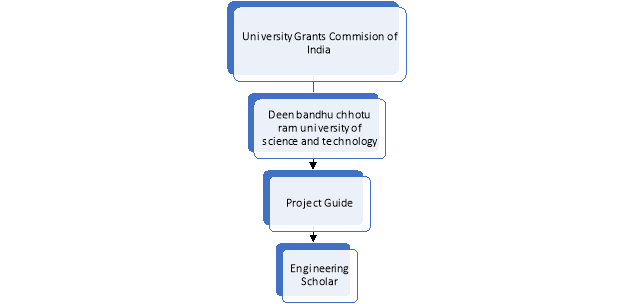
The reporting structure along with my role, of the project has been demonstrated with the help of chart. My role in the project was of engineering scholar who has to perform all the project activities individually.
C.E.1.2.5 DUTIES AND RESPONSIBILITIES
As I was the sole owner of the project, so all the project activities were carried out by me under the guidance of “Project Guide”. Below mentioned are details of the duties and responsibilities.
I did the thorough analysis of the rolling motion and its importance in the various other mechanisms, along with learning MATLAB coding language and Bond Graph Approach.
I tried to evaluate the benefits of the targeted problem along with effort measurement.
After finalizing the problem, I created bond graph model of the dynamics of the rigid body.
I integrated the bond graph model of the rigid body with the interface dynamics.
I did the frictional analysis between the body and elastic surface (system).
I merged the proportional derivatives to the system to convert system into controlled motion system.
I performed the detail analysis of the final bond graph model of the system for the required output.
I created the MATLAB code for the overall bond graph model of the system.
I tested the simulated model in MATLAB system for different variations.
I analyzed the output of the simulated model and compared the results with desired ones.
I finalized the way of simulation showcasing in MATLAB.
C.E.1.3 ENGINEERING ACTIVITIES
C.E.1.3.1 PROBLEM IDENTIFICATION AND DEFINATION
First and the foremost important task of the project was to define the problem and finalize the scope of the work. The problem definition includes different task which are mentioned below:
Problem identification
This includes analysis of the benefits of the problem solving in today’s world and in future. Also, in this step, benefits of the solution need to be compared with efforts, to finalize the problem. In my project, after analysis I found that outcomes of the project outweigh the efforts and can be highly beneficial for other scholars.
Problem definition
This step includes the finalizing an appropriate definition of the problem in an understandable manner. In my project, in this step created the definition of the project which exactly shows my work.
Project Scope
In this step, limits of the project are defined to finalize the extent of the work need to be included. In my project, I finalized that I will focus only on the elastic surface and not include non-elastic surface for the analysis.
C.E.1.3.2 LITERATUTRE SURVEY
This step includes the analysis of the history of the problem and related topics. In this step, I drilled down in the various researches, which were carried out earlier on the similar kind of problem. This helped me to gain insights of the various techniques now researchers are using to solve this kind of problems.
C.E.1.3.3 RIGID BODY DYNAMICS FORMULATION OF THE SYSTEM
In the rigid body dynamics formulation, I defined the basic rigid body on the surface of an elastic material. The equation of the dynamics of a point are formulated first. Below shows the pictorial representation of the point P with respect to a moving and an inertial frame.
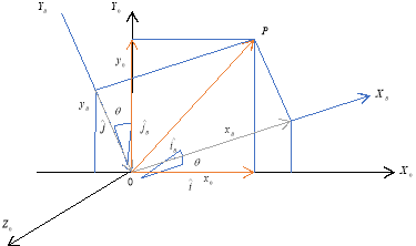
After creating the point equation, then I integrated it to create an “Rigid Body”. The integrated equation gave me, the dynamics of the rigid body with respect to a moving and a inertial frame. Below is the pictorial representation of the rigid body with respect to two frames.
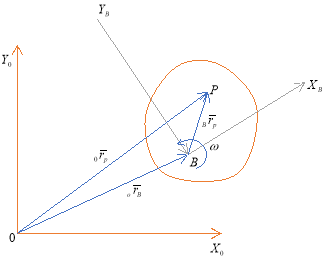
The equation mentioned below served the basis of the analysis.

C.E.1.3.4 BOND GRAPH MODELING OF THE SYSTEM
For Bond graph modeling of the system, I assumed a thin layer of elastic material between the disc and surface as demonstrated with the help of the picture.
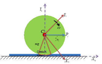
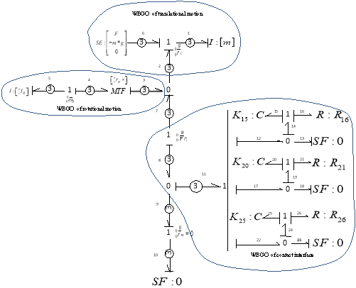
With this assumption, I created a bond graph model of the different subsystem also known as “Word Bond Graph Object” (WBGO). WBGO are created for rigid body dynamics and contact interface separately. After that, I integrated the two WBGO to obtain the dynamics of the rolling motion on the thin sheet of elastic material. The final bond graph model is shown in the picture below.
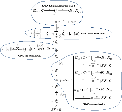
After creating the bond graph model of the system, I created the WBGO of the proportional derivative (PD) controller and added that, to the system. The purpose of the PD controller is to control the velocity of the disc using distance and time. The WBGO of the whole system along with the PD controller is shown in the picture below.
C.E.1.3.4 SIMULATION AND ANALYSIS
C.E.1.3.4.1 INTRODUCTION
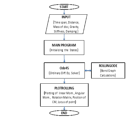
After the creation of the bond graph model of the whole system, I created the code for the simulation in MATLAB platform. For this, I used ODE45 solver as the equation from the bond graph can be directly used in the ODE45 solver.
Below shown is the flow chart that I created for the simulation code.
Below mentioned are the major parameters that i used in Simulation:
|
PARAMETERS OF DISC |
VALUE |
|
Radius of disc |
0.05 m |
|
Thickness |
0.005 m |
Table1: Parameters of disc
|
PARAMETERS |
UNITS |
Values |
|
Time Span |
Second |
[0 2] |
|
Mass of disc |
Kilogram |
0.5 kg |
|
Stiffness of springs k15 k20 k25 k30 |
Newton per meter |
10000 N/m |
|
Damping coefficients of dampers R16 R21 R26 R31 |
Newton-sec per meter |
20Ns/m |
C.E.1.3.4.2 SIMULATION RESULTS
I tested the model through simulation and simulation results are discussed below.
C.E.1.3.4.2.1 SIMULATION AND ANALYSIS OF THE RIGID BODY DYNAMICS WHILE ROLLING
In this simulation, I simulated and analyzed the dynamics of rigid body while rolling. I applied a horizontal force of 1 Newton at the center of mass of the disc to provide motion. Various states are shown with the help of graphs below
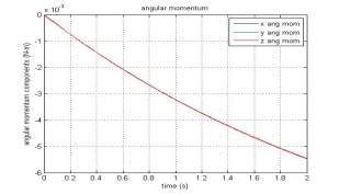
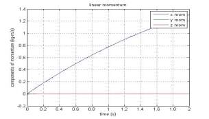
linear momentum with respect to time Angular momentum with respect to time
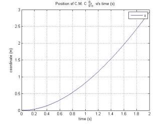
Position of center of mass with respect to time
C.E.1.3.4.2.2 SIMULATION AND ANALYSIS OF THE RIGID BODY DYNAMICS WHILE ROLLING CONTROLLED BY PD CONTROLLER
In this simulation, I simulated and analyzed the dynamics of rigid body while rolling, controlled by PD controller. PD controller helps to control and give jerk free motion to the disc. Various states are shown with the help of graphs below.
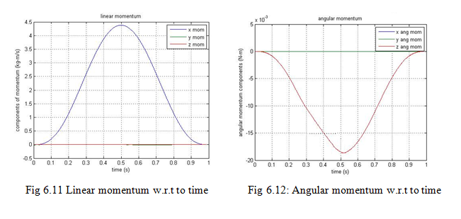
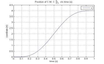
Position of center of mass with respect to time
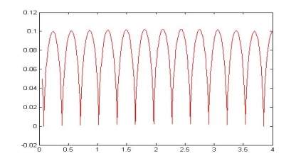
Figure 6.17 Locus of a point on the circumference of the disc
C.E.1.4 APPLICATION OF ENGINEERING KNOWLEDGE AND SKILLS
In this project, I applied numerous engineering skills to solve the problem. Few of them are listed below
First, identifying a technical problem requires immense amount of topic research. Literature survey of the previous researches helped me to identify and then define the problem.
Second, I applied rigid body dynamics knowledge to study the rolling motion and its effect on its environment.
Third, I learnt and applied Bond graph technique to the system to put all the conversions on one platform.
Fourth, I applied the coding knowledge of MATLAB to simulate the problem.
Last, I applied the knowledge of Microsoft office to present the work in a understandable manner.
C.E.1.5 MAJOR CHALLENGES
In this project, I faced several challenges which enhanced my skills in the end. Details are highlighted in the below mentioned bullet points.
The foremost challenge was to identify and define the problem. As I already mentioned, literature survey of the previous researches helped me to overcome this hurdle.
Learning the basics of rigid body dynamics was another challenge, in which my guide helped me immensely.
Bond Graph approach was an all-new technique for me, as it was never been in my curriculum. Learning a new approach with in stipulated time was a hard task to accomplish.
Learning a new coding language MATLAB as mechanical engineer was another tough task for me.
Completing the project in the time frame was biggest challenge. I putted huge effort and time to solve the problem along with carrying out the documentation, in which my time management skills helped me.
Lastly, satisfying the panel with the work and project details was another challenge. I answered all the queries of the panel to satisfy them. Also, I demonstrated the work in very effective and understandable manner with help of my Microsoft office skills.
C.E.1.6 SUMMARY
This project taught me numerous things related to time management and documentation.
I learnt how to apply the engineering skills to execute the project and deal with in-between challenges.
In this project, I acquired new engineering skills like MATLAB coding and Bond graph technique, which could be fruitful for me in the future.
I also learnt how to identify a problem and various ways of solving them, along with opting for the best solution.
This project also helped me to enhance my decision-making skills.
I also learnt how to carry out a research project in a timely manner.
As it was a single-handed project, it helped me to learn, how to carry out any project individually and make it a success.
As I was the first to submit my project, I received appreciation from my guide and institute along with the post graduate degree in mechanical engineering.
Cite This Work
To export a reference to this article please select a referencing stye below:
Related Services
View allDMCA / Removal Request
If you are the original writer of this essay and no longer wish to have your work published on UKEssays.com then please click the following link to email our support team:
Request essay removal


