Energy Conversion & Energy Transfer Assignment
| ✅ Paper Type: Free Essay | ✅ Subject: Engineering |
| ✅ Wordcount: 905 words | ✅ Published: 31 Aug 2017 |
- The technical specification for a transformer may be found by examining its name plate.
All transformers on the distribution and transmission network have a name plate. This plate has useful information about the transformer, e.g. – how it is cooled, its KVA rating, the year it was mad and its LV – HV arrangement. The information is stamped or etched on so it is permanent. [1]
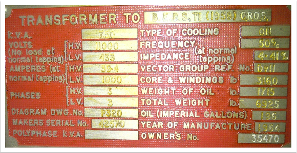
Image 1 SSE GMT Dorset
- KVA – This is the transformers apparent power rating.
- Volts – This is the Primary and Secondary voltages values of the transformer
- Amperes – This is the Max current rating for the transformer
- Phases – The amount of phases on the HV and LV sides
- Diagram DWG No – Transformer schematic reference number
- Makers Serial No – This is the serial number from the transformers manufacture
- Polyphase KVA –
- Type of cooling – The way the transformer is cooled
- Frequency – Number of cycles per second in an alternating current
- Impedance – A ratio of the transformers normal full load current to the current available under short circuit conditions
- Vector group ref – indicates the windings configurations and the difference in phase angle between them
- Core and windings – This is the weight of the core and windings
- Weight of oil – This is the oil weight
- Total weight – this is the combined weight of the oil, core and windings
- Oil – This is the amount of oil in the transformer
- Year of manufacture – This is the year the transformer was made
- Owners No – This is where the owner of the transformer can label there asset
With electrical machines it is very often the temperature rise permitted in the windings and insulation that determines the output, this applies particularly to transformers.
Transformers are identified according to the cooling medium employed and its circulation method. The designated letters are assigned.
|
Medium/Method |
Symbol |
|
|
Cooling Medium |
Mineral Oil Gas Water Air Synthetic Insulating Liquid |
O G W A L |
|
Circulation Method |
Natural Forced Forced Directed |
N F D |
The identification code used consists of 4 letters giving details of the cooling medium and circulation method for both primary and secondary cooling system.
|
1st letter – Method |
2nd letter – Circulation |
3rd letter – Medium |
4th letter – Circulation |
|
Cooling medium in contact with winding |
Cooling medium in contact with external cooling system |
||
2. The following items are associated with power transformers.
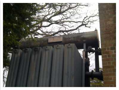
Conservator tank
The oil conservator is a single protecting device made of sheet steel, resistant or not to vacuum. It is
cylindrical and has two fixing brackets. Usually, it is placed on a structure fixed on the transformer,
above the cover level. In each side of the conservator there is one hole allowing its eventual washing during the exploitation. This hole is closed by means of a plate, which can hold (depending on the needs) an oil level magnetic indicator.
The conservator has several holes to which are connected the corresponding piping. Each one of
these piping has its specific activity (connection to the air breather, to the transformer cover,
sampling, etc.). If the transformer is equipped with on-load tap changer, the conservator is divided by a septum. The larger compartment feeds the tank of the transformer and the smaller one feeds the on-load tap changer-breaking chamber. [3]

Buchholz relay
Every type of fault which occurs in oil filed transformer gives rise to the generation of gas which may be slow in the case of minor faults or violent in the case of major faults. The Buchholz relay is inserted in the pipe connection between the transformer tank and conservator. The Buchholz relay comprises of a cast iron housing which contains 2 elements. A mercury float switch which detects a fall in oil level and a combined deflector plate and float switch mounted so that it will detect any rapid movement of oil from the transformer to the conservator.
The slow production of gas due to a minor fault causes a stream of bubbles to pass into the Buchholz chamber, resulting in a slow displacement of the oil and lowering the upper float which when sufficient will generate a “Buchholz Alarm”.
A serious fault will produce an explosive generation of gas which rapidly displaces the oil and causes a surge to pass along the pipe towards the conservator and in doing so displaces the deflection plate, operating the lower switch which produces a “Buchholz Trip” which causes the transformer circuit breaker to trip.
A leakage of oil from the transformer tank causes a gradual fall in the level of oil which when sufficient will be seen by the “Buchholz Alarm” float switch.
The relay is also fitted with a petcock which can be used to take oil samples for analysis of the fault.
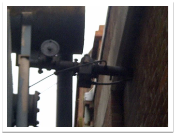
Image 3, SSE S/S Paisley Road, Southbourne, Buchholz relay
Neutral Earthing Resistor (NER)
Neutral earthing resistors are a type of protection device, protecting equipment when there is a fault on the network. They work by restricting the amount of voltage and current that flows through the neutral point of the transformer its connected to, to a level that is safe preventing any damage. Neutral earthing resistors are generally connected between ground and neutral of the transformer. [2]
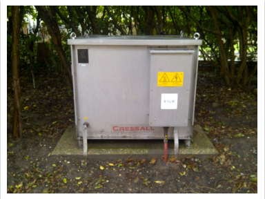
Image 4, SSE S/S Paisley Road, Southbourne, NRE
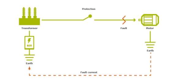
Image 5, NER Diagram – [2]
3. Circulating currents can sometimes occur in a power transformer, explain why this happens and whether it is a good thing for power transmission and distribution networks.
[4]
References
[2] https://www.captech.com.au/solution/neutral-earthing-resistor/
[3] Table from SSE Document Library Ref: TG-PS-445 33kV transformers
[4] http://www.gozuk.com/blog/circulating-current-in-parallel-transformers-585733.html
Cite This Work
To export a reference to this article please select a referencing stye below:
Related Services
View all


DMCA / Removal Request
If you are the original writer of this essay and no longer wish to have your work published on UKEssays.com then please click the following link to email our support team:
Request essay removal