Effects of Magnetic Fields Produced from Long Wires
| ✅ Paper Type: Free Essay | ✅ Subject: Engineering |
| ✅ Wordcount: 2075 words | ✅ Published: 30 Aug 2017 |
Faraday’s Law Laboratory Exercise
An investigation into the effects of magnetic fields produced from long wires and comparison of theoretical and experimental results through the use of Ampere’s Law and Faraday’s Law
Contents
3.2 Single wire experiment with Ferrite Core
Electromagnets and the magnetic fields that they produce provide the foundations for the development of various major industries in modern society, including medicine, transport and robotics. However, there can be inaccuracies with their use caused by a phenomenon known as Electromagnetic Interference (EMI). In this experiment, a search coil was placed near a fixed wire with a current flowing through it, and the induced voltage across the coil was measured and recorded as the coil was moved away from the wire to investigate the effect of distance on the magnitude of the magnetic flux while the effects of a ferrite core on the magnetic field produced were also explored. The experimental and theoretical results highlighted the same trends, confirming the expectation that an increase in distance would cause a decrease in the magnitude of magnetic flux. The differences in results can be considered due to EMI from the return connection, which can induce unwanted voltages in the circuit.
A magnetic field is the ‘region in the neighbourhood of a magnet, electric current or changing electric field in which magnetic forces are observable.’ (1) An electromagnetic field is the form of magnetic field generated by the flow of electric current; it is caused by the movement and acceleration of the electrons. (2) Electromagnets play an important role in the continued development of many major industries, while there are already numerous useful applications of them in modern society. The electromagnetic fields they produce are vital in: medical practises such as MRI scans where they are used to alter the alignment of hydrogen atoms in the body (3); the production of high-speed ‘Maglev’ trains which eliminates friction by allowing the train to ‘levitate’ (4) and the continued scientific research into superconductors and rapid acceleration which provides the basis for particle accelerators. (5)
However, constantly changing electromagnetic fields, especially in electric circuits, can cause a phenomenon known as Electromagnetic Interference (EMI) which can induce unwanted voltages and affect the performance of electronic devices. The area of engineering which aims to eradicate the problems caused by these disturbances is known as Electromagnetic Compatibility (EMC). (6)(7)
Two equations which form the fundamental basis for electromagnetism and its understanding are Ampere’s Circuital Law and Faraday’s Law.
Ampere’s Law states that the magnetic field, B, caused by an electric current is proportional to the size of the electric current. (8)
 (equation 1)
However, in this experiment, the current, I, flowing through the circuit remains constant, as does the permeability of free space,  , and 2Ï€, and therefore the magnetic field, B, is expected to be inversely proportional to the distance from the wire.
Faraday’s Law states that any change in the magnetic environment of a wire will cause a voltage to be induced in the wire. (9)
 (equation 2)
If  = BA and a sinusoidal variation of the magnetic field is assumed:
 (equation 3)
where  is the induced voltage, N is the turns on the coil, A is the area of the coil and
  is the angular frequency. As N, A and are constant, the magnetic field, B, should be directly proportional to the induced voltage, E, in this investigation.
 2.1 Introduction to Method


2.1.1 Apparatus
Agilent signal generator to vary the frequency of the signal provided to the circuit.
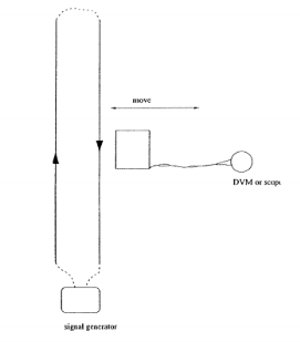
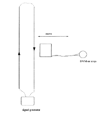
Twin wire board as shown in figures 1 and 2, containing a fixed wire, an adjustable return connection wire and a 50Ω resistor in series with the circuit.
Rectangular air cored coil of dimensions 30mm x 30mm and containing 50 turns, used to measure the changing B field from the wire.
Ferrite core to alter the effects of the B field on the coil.
Digital Multimeter to record the voltages across the resistor and the search coil, measuring with an uncertainty of +0.0005mV.
2.1.2 Procedure
The long wire board was connected to the Agilent signal generator, ensuring that the 50Ω resistor was in series with the circuit. One connection was made using the fixed wire on the board; the other was made using a long connection lead kept the farthest distance away from the experiment as possible, as demonstrated in figure 1. A sign wave signal of frequency 60kHz was selected and the voltage across the resistor recorded, allowing a current to be calculated. The rectangular search coil was then placed against the fixed wire 2cm away from the centre line and the voltage across the coil measured. The coil was then moved at a right angle away from the fixed wire in increments of 1cm and the voltage across the coil measured at each of these points. The input sign wave frequency was then altered to 30kHz and the experimental procedure was repeated. The input sign wave frequency was then returned to 60Hz and a round ferrite core inserted into the search coil; the experiment was then repeated again.
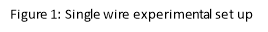
The long connection lead was then changed to provide a short connection as shown in figure 2. A sign wave signal of frequency 60kHz was again selected and the current calculated. The rectangular search coil was then placed against the short connection wire 2cm away from the centre line and the voltage across the coil measured. The coil was then moved in the same manner as above and the voltages recorded. The input sign wave frequency was again altered to 30kHz and the experiment was repeated.
The current through the circuit was calculated using Ohm’s law:
where V is the measured voltage across the resistor (3.385 V) and R is the known resistor value 50Ω, giving  = 191mA.
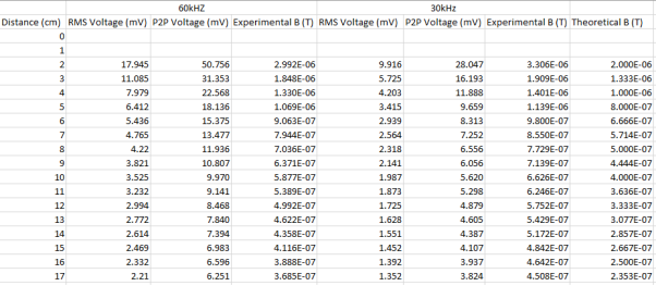
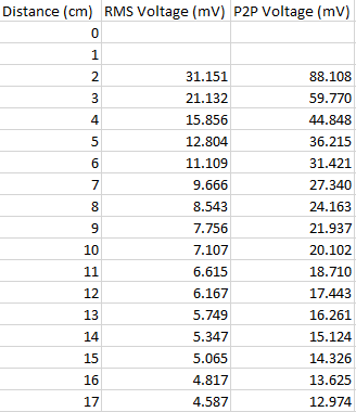
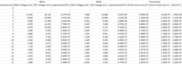
For the single wire and double wire at both frequencies, and the single wire at 60kHz with the ferrite core, the distance of the search coil away from the wire, d, and the RMS voltage across the search coil, E, were recorded and collected in three tables which can be found in Appendix A. The RMS voltages measured were then converted into peak-to-peak voltage values for use in equation 3. The resultant experimental B fields for the respective frequencies were then calculated using equation 3, using N = 50 and A = 9x and included in the tables.
3.1 Single Wire Experiment
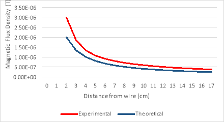
For the single wire experiment, theoretical values for the magnetic flux density at each distance were then calculated using equation 1. A graph of B against the distance from the wire was then plotted for both frequencies and a comparison between experimental and theoretical values made on both graphs.


3.2 Single wire experiment with Ferrite Core
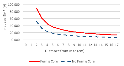
With the ferrite core introduced into the search coil, at a frequency of 60kHz, the voltage across the search coil was measured and a graph of the induced EMF, V, against distance plotted. The induced EMF without the ferrite core is also plotted for reference.

3.3 Double Wire Experiment
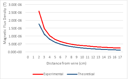
For the double wire experiment, two theoretical values for the magnetic flux density were calculated; one for the magnetic flux induced by the fixed wire and one for the magnetic flux induced by the short connection wire. These were both calculated using equation 1, using a reference of +0cm for the short connection and +15cm for the fixed wire. These values were then combined using the principle of superposition and an overall theoretical value for magnetic flux density at each distance calculated. Again, a graph of B against the distance from the wire was plotted for both frequencies and a comparison between experimental and theoretical values made on both graphs.

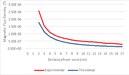

It was expected that as the distance of the search coil away from the fixed wire increased, the voltage induced across the coil would decrease and therefore the magnetic flux density, B, would also decrease. A comparison of the experimental and theoretical data points from figures 3 and 4 shows a clear correlation between the two calculations, confirming the theory discussed in section 2 of the report. The slight discrepancies between the experimental and theoretical values can be accredited to possible electromagnetic interference (EMI) from the long connection lead, inducing unwanted voltages across the coil and affecting the accuracy of the results.
The scale of magnetic flux is affected by the angle at which the flux density and the surface interact such that  , where θ is angle between the magnetic flux, B, and the normal to the surface. When the normal to the coil is parallel to the wire, θ = 90° and therefore cos(θ) = 0, proposing that the theoretical value of magnetic flux is 0. When the coil was placed perpendicular to the fixed wire, a voltage of 0.541mV was measured, which can be approximated to 0V. The small induced voltage can be considered due to the presence of a background magnetic field.
With the ferrite introduced into the search coil, the emf induced in the coil is measured to be significantly larger than with no ferrite present, as can be seen from figure 5. Due to the high magnetic permeability of a compound such as a ferrite, the magnetic field produced by the coil is concentrated in the core material, reducing the effects of EMI and increasing the induced emf in the coil. (10)
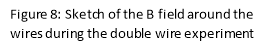
 In the double wire experiment, the voltage induced in the search coil is created through a combination of the magnetic fields produced from both the fixed wire and the short wire. Because it is a series circuit, the current is flowing in opposite directions in each of the wires and consequently, from the right-hand rule, the magnetic fields from each wire are also acting in opposite directions, demonstrated in figure 8. Therefore, it would be expected that the induced voltage across the coil, and subsequently the magnetic flux, B, would be smaller than those measured in the single wire experiment and this is confirmed through the values shown in Appendix A. As the coil is moved away from the wires, the magnetic field weakens but at a decreased rate as the distance increases; therefore, we would expect a graph displaying a reciprocal nature, achieved in figures 3 and 4.


To conclude, the experiment outlined in this report was successful in demonstrating the effects of magnetic fields produced by long wires and the effects of ferrite on the emf induced in a coil, successfully validating the theory from section 2 that the magnitude of the magnetic flux field, B, is proportional to the reciprocal of the distance of the coil from the wire.
However, the consistently higher experimental values compared to the theoretical values clearly demonstrates the possible disturbances arising from the interaction between two different magnetic fields and highlights the need to minimise these to achieve accurate results. Through the introduction of a ferrite core, this experiment was successful in demonstrating a simple method for this.
The findings from this experiment are statistically insignificant due to the nature of the apparatus used and the various possible sources of error, both systematic, because of EMI, and human, arising from the low level of accuracy when measuring distances and ensuring the coil remains parallel to the wire. However, the experiment was useful in showing the basic relationship between distance and the strength of magnetic flux, as well as highlighting the importance of finding solutions to reduce the effects of EMI on induced voltages and introducing a simple method for realizing this.
|
[1] |
Encyclopaedia Britannica, “Magnetic Field,” Encyclopaedia Brittanica, [Online]. Available: https://www.britannica.com/science/magnetic-field. [Accessed 19 October 2016]. |
|
[2] |
M. Rouse, “Electromagnetic Field,” March 2010. [Online]. Available: http://whatis.techtarget.com/definition/electromagnetic-field. [Accessed 20 October 2016]. |
|
[3] |
Institute of Physics, “Magnetic Resonance Imaging,” 2012. [Online]. Available: www.iop.org/education/teacher/resources/teaching-medical-physics/magnetic/file_56290.pdf. [Accessed 20 October 2016]. |
|
[4] |
K. Bonsor, “Maglev Train,” 13 October 2000. [Online]. Available: http://science.howstuffworks.com/transport/engines-equipment/maglev-train.htm. [Accessed 19 October 2016]. |
|
[5] |
M. Williams, “Use of Electromagnets,” 13 January 2016. [Online]. Available: http://www.universetoday.com/39295/uses-of-electromagnets/. [Accessed 21 October 2016]. |
|
[6] |
Andi, “What is electromagnetic interference and how does it affect us?,” [Online]. Available: https://www.westfloridacomponents.com/blog/what-is-electromagnetic-interference-emi-and-how-does-it-affect-us/. [Accessed 21 October 2016]. |
|
[7] |
M. Soleimani, “Faraday’s Law,” University of Bath, 2016. |
|
[8] |
D. Wood, “Ampere’s Law: Definiton & Examples,” [Online]. Available: http://study.com/academy/lesson/amperes-law-definition-examples.html. [Accessed 22 October 2016]. |
|
[9] |
Hyper Physics, “Faraday’s Law,” [Online]. Available: http://webcache.googleusercontent.com/search?q=cache:85jQ17DaK1wJ:hyperphysics.phy-astr.gsu.edu/hbase/electric/farlaw.html+&cd=2&hl=en&ct=clnk&gl=uk. [Accessed 21 October 2016]. |
|
[10] |
Wikipedia, “Magnetic Core,” [Online]. Available: https://en.wikipedia.org/wiki/Magnetic_core. [Accessed 23 October 2016]. |
 Single Wire
Single Wire with Ferrite Core
 Double Wire
Cite This Work
To export a reference to this article please select a referencing stye below:
Related Services
View all


DMCA / Removal Request
If you are the original writer of this essay and no longer wish to have your work published on UKEssays.com then please click the following link to email our support team:
Request essay removal