Effects of the Geometrical Conditions on Side Channel Pump
| ✅ Paper Type: Free Essay | ✅ Subject: Engineering |
| ✅ Wordcount: 3853 words | ✅ Published: 30 Aug 2017 |
Effects of the Geometrical Conditions on the Performance of a Side Channel Pump: A review
Appiah Desmond, Zhang Fan, Yuan Shouqi and Osman Majeed Koranteng
National Research Center of Pumps, Jiangsu University, Zhenjiang 212013, China
Abstract
The side channel pump is a type of regenerative pump which plays a role in between the centrifugal pump and the positive displacement pump. This kind of pump delivers a high head at relatively small flows compared with other axial and centrifugal pumps even though it requires a low specific speed. This paper firstly focuses on the physical principle behind the flow characteristics illustrating the complex flow inside the side channel pump. Further discussions disclosed that, the hydraulic performance of the pump greatly depends on the variations of the geometrical parameters. This review draws conclusion that, enhancement of the computational modeling techniques will improve the efficiency of this pump thereby broadening its applications.
Keywords: Side Channel Pump, Hydraulic Performance, head, geometrical parameters, computational modeling
1.0 Introduction
The side channel pump since its inception in 1920 by Siemen and Hinsch [1] has had great influence in the world of engineering. This pump plays a role in between the centrifugal pump and the positive displacement pump. The side channel pump is a kind of regenerative pump which has a low specific speed and requires minimal Net Suction Pump Head (NSPH). Due to its unique properties to self-prime and transports both liquids and gas, it has been used mainly in the fields of oil and gas industry, mining and other applicable fields. Most of these pumps have the ability to handle liquid with gas or vapor inclusions up to about 50% and also other media close to their boiling point [2]. The side channel pumps base its operation on the momentum transfer principle moving from the impeller blade to the fluid in the side channel of the pump [3, 4].
The side channel pump delivers a large head performance at relatively small flows [5]. The fluid gets into the pump and leaves after numerous impeller movements. The fluid velocity and its head increase causing it to have the capability to produce a head (pressure) compared to the axial and centrifugal pumps. Due to the smaller pressure difference, a fluid entering this type of pump closer to its vapor pressure is less susceptible to the pressure change that can bring about cavitation[4]. Over the years, the enhancement of the total efficiency of this pump still remains a challenge to engineers and scientist. The flow rate of fluid in the side channel pump is significantly influenced by the impeller designs on this basis urgent attention needs to be given to the design and optimization of the impeller and side channel [5, 6].
2.0 Flow Mechanism
The side channel pump mainly features a side channel in figure 1a. and an impeller usually with 18 to 26 blades figure 1b, which delivers the fluid circumferentially. The assembly of the side channel and the impeller is shown in figure 1c. The fluid flows in a straight line from the inlet of the pump and leaves through the outlet in a helical form after numerous re-entries into the rotating impeller. This effect causes an upturn in the pump head (pressure) from about 5~10 times better than the impeller of a common pump rotating at the same speed [5, 6].
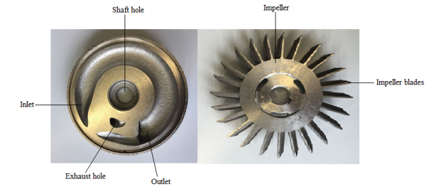
- side channel (b) radial impeller
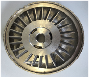
- The assembly of side channel and impeller
Figure 1: Typical side channel with radial impeller
This makes the flow of fluids in this kind of pump very complex as depicted in figure 2. The pump does not transport the same volume of fluid that enters out meanwhile some portion of the fluid moves back into interrupter gap and is conveyed by the pressure side of the blade to the suction side [6]. Shirinov and Oberbeck [3] explained the movement of gas in the side channel pump. They pointed out that the momentum acquired by the blades of the impeller is transferred to the gas. The velocity of the gas is then increased both in the axial and radial direction by the impeller blades in the side channel.
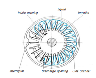
Figure 2. Flow pattern of liquids in the Side Channel Pump [5]
The turbulence and the circulation models are largely used to describe the performance of the pump and also the characteristic curve computation. The side channel pump efficiency is usually below 40% because it is a type of a regenerative pump [5, 6]. Basically, the flow is very dependent on the orientation of the impeller, impeller blade and the side channel. There are many configurations of the impeller blade and shapes of the channel as depicted in figure 3 by Song et al. [7].
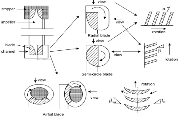
Figure 3: Different kinds of blade and channel shapes [7]
A study by Senoo [8] on the influence of the developing area for different geometries of the inlet region of the regenerative pump observed the large channel region at the inlet port as capable of developing high pressure head leading to a better cavitation performance of the pump. Song et al. [7] developed a model for the flow theory in the regenerative pump to help address the lapses in the works of Senoo[8] and Wilson et al. [9] which mainly concentrated on the exchange of momentum of the flow. There were inaccuracies of some of the models suggested by [8, 9] to reduce the losses and slip factor links. This made the accurate prediction of the off-design flow conditions very incapable. Song and his colleagues [7] concentrated on introducing vibrant mathematical algorithms demonstrating the true behavior of the flow in the developing area of the inlet region. They based their research on assumptions which guided them in arriving at some meaningful conclusions. The velocity triangle relation between absolute velocity, V relative velocity, W and the impeller velocity, U was defined based on the velocity triangle in figure 4 at blade inlet, R1 and blade outlet, R2.
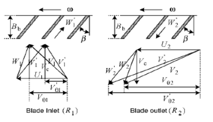
Figure 4: Velocity triangle at locations R1 and R2 [7]
From figure 5, there is no tangential velocity in the front and rear faces of the blade region. Thereby, the continuity was defined in equation 1 based on their first assumption that the flow should be steady and incompressible.

 (1)
(1)
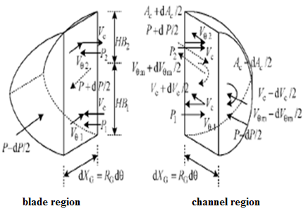
Figure 5: Elements of one side channel and blade [7]
They developed the first-order nonlinear Ordinary Differential Equation (ODE) for predicting the circulatory velocity which showed a good agreement when its results were compared with that of experimental results.
A new branch of fluid mechanics developed in the last decades called Computational Fluid Dynamics (CFD) has been employed lately in the modern engineering science to analyze the flow of fluids in turbo machines. The study of the fluid flow in the side channel pump using the CFD tool and an analytical method was the centered of BÓ§hle and Muller’s [10] research. They developed an analytical model for the flow taking into consideration some assumptions. A momentum balance was expressed for the control volume of the flow in a circumferential course.
 (2)
(2)
Where Cin = uniform velocity in circumferential course
Csc = uniform velocity in the side channel
á¹exch = mass exchange flow
p = static pressure
A =Side channel cross-section area
A1 = surface control volume
Ï„ = mean shear stress
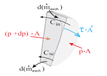
Figure 6: momentum balance [7]
The efficiency of the impeller and side channel was defined as
 (3)
(3)
Where ηimp = impeller efficiency
Pexch = Exchange work Power
Pshaft = Power of shaft
Phydr = Hydraulic power losses
 (4)
(4)
Where ηsc= side channel efficiency
Peff = effective power
á¹ = side channel pump mass flow
g = acceleration due to gravity
H = head of side channel pump
Cin = uniform velocity in circumferential course
 = flow rate volume
A =Side channel cross-section area
Based on the efficiencies of the impeller and the side channel, the efficiency of the side channel pump, η was computed to be
 (5)
(5)
Later, Kristof and his colleagues [11] also applied the CFD to model the flow course in the side channel pump as displayed in figure 6. A technique was modeled to optimize the orientation of the blade and the shape of the side channel to control the flow losses. They carried out simulations with the k-ω turbulent conditions based on a 40100 cell tetrahedral mesh.
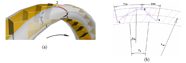
Figure 6(a) and (b): Typical flow course with the side channel pump [11]
In 2005, Engeda and Raheel [12] presented mathematical tools capable of examining the complex flow inside the regenerative pumps. These mathematical tools were used also used to develop the prediction performance code for regenerative pumps
3.0 Effects of the Geometrical design of the parameters of the Side Channel Pump
The performance of the regenerative pump was examined by Iverson [13] with his focus on the shear stress generated by the impeller on the fluids. He then confirmed on his resulting expressions (two shear coefficients and an average impeller velocity) through experimentations. A mathematical tool was proposed by Wilson et al. [9] to investigate the performance of regenerative pumps which used radial blades. Equal pressure head rise and circulatory velocity through the channel region was anticipated by Wilson and his team. Much attention was given to the spiral flow to achieve many ways of curtailing the losses. Their results provided experimental verification after comparing the numerical and experimental performance curves. Yoo et al. [14] also tried to develop advanced mathematical equations to calculate the geometry of the rotating flows. They offered enhanced models to examine the flow rate, the average radii of the inlet and outlet impeller and the slip factor based on the exchange of momentum proposal by Wilson et al [9]. The models required an experimental boost to evaluate an empirical number in the proposed experimental model. The effect of the blade angle was not considered thus limiting the applicability as a design tool.
The variation of the radial blade numbers, the clearance and the channel region of regenerative pumps were conducted by Shimosaka and Yamazaki [15]. Investigations conducted by varying the dimension of flow channels, impellers and clearances on a regenerative pump concluded that, the characteristic dimension of the flow channel is related to the clearances effects, which in turn influences the pump efficiency. The characteristic dimension of the flow channel was introduced as a special dimension which was given as:
 (6)
(6)
Where Rmis the characteristic dimension of flow
A is the cross-sectional area of the flow channel
 is the circumferential length of the blade(vane)
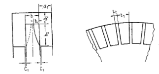
Figure 7: Flow channel and blade profile
They reported that a suitable Rm would yield a high efficiency of the pump. Therefore, the value of the Rm determines the permissible clearance. The pump efficiency was also strongly influenced by the number of blades (vanes) which is dependent on the characteristic dimension of the flow channel, the thickness and length of the blade and the width ratio as shown in figure 7. It was established that the efficiency of the pump varies with different width ratios of the vane groove which aids in the determination of the blade number.
Width ratio, (7)
(7)
Defining Z = Number of blades
D = Diameter of impeller
t1 = Peripheral width of blade groove
t2 = Peripheral length of blade groove
Additionally, Yamazak et al. [16] also carried out works to investigate the efficiency of the regenerative pump. Unlike Shimosaka and Yamazaki [15], they used the non-radial blades and concluded that the blade angle and the cross-sectional area of the flow channel play a vital role in the determination of the head (pressure) loss in the flow channel.
Δh = Hs – Hmin(8)
Where Δh = the magnitude of head loss
Hs = the suction head
Hmin = the minimum pressure head in flow
It was noted that the magnitude of Δh reduces to almost half that of water with the same velocity in the event of high viscous liquid. Motivated especially by the observations made by [15, 16], Grabow [17] also took into consideration the effects of the impeller, the number of blades and the role of the radii and thickness of the blades during his research study. The blade angles were varied to define a very satisfactory exchange of energy and pressure head levels, which in effect helps to evaluate cavitation performance better. Bartolini and Romani [18] also affirm that, the flow rate of the regenerative pumps depends on the optimization of the impeller flow. A new theory was proposed by Badami [19] on the calculation of the circulation flow rate of the regenerative pumps. This model took into account the field of the centrifugal force in both the side channel and the blade orientation. Also, his work also considered the influences of the geometry of the blades (number and angles) and the area of the side channel. Earlier it had been discussed by Sachs and Shirinov [20] that the best number of blades depends directly on the diameter of the impeller and inversely proportional to the side channel’s size. After that work, Shirinov and Oberbeck[3] then focused their investigations on the transportation of gas in the side channel pump by using different blade profiles. They compared C, V, and Y blade profiles with the radial (T) blade profile as shown in figure 8.
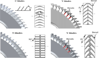
Figure 8: Impeller with different blade profiles
After comprehensive comparisons, it was established that blade profile C gave an optimal performance at pressures exceeding 20kPa meanwhile at pressures from 100Pa to 20kPa, the impeller with blade profile V (Chevron) recorded an optimal performance because there was a high transfer of momentum from the impeller to the gas inside the side channel within such pressure range. An extensive experimental research was also conducted by Choi et al. [21].Their work was mainly focused on the limitations of [14, 15, 17]. They examined the effects of the geometry on the blade on the efficiency of regenerative pumps. Ten different configurations of blades which comprised straight inclined blades with angles of 0°, ±15°, ±30° and ±45° and chevron impeller blade with chevron angles of 15°, 30°, and 45° were used in conducting the experiments. The measured performance of the pump were measured based on the dimensionless flow ϕ, head coefficient, ψ, efficiency, η and power coefficient, τ.
 (9)
(9)
Where Q = volumetric flow rate
Qs= rigid-body rotational volume displacement rate
 (10)
(10)
H = head
Ug = rigid body rotation velocity
g = acceleration due to gravity
 (11)
(11)
The experimental results showed that the pressure head and the pump efficiency is greatly related to the geometry (shape and angle) of the blade as revealed in figure 9(a) and 9(b).
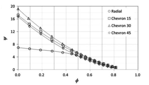
Figure 9(a). Pump curve characteristics for the different blade orientation [21]
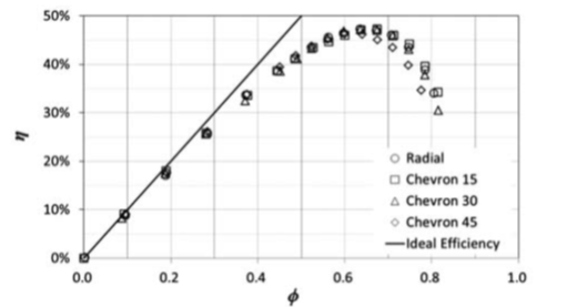
Figure 9(b). Efficiency curve characteristics for the blade orientations [21]
The chevron blade(V-shaped) with chevron angle of 30° recorded the highest head performance with a better pump efficiency as revealed in figure 8(a) and 8(b) after a comparative test of all the ten blades showing that there was an optimum chevron angle of around 30°. This report showed good agreement with the work of [3] because of the high energy transfer at high pressures. The variation of the Reynolds number plays an important role in the performance of the regenerative pump computationally and experimentally. It was established by Horiguchi et al. [22] that, as the Reynolds number declines the pressure head of the regenerative pump rises at low flow rate and reduces at high flow rate. This effect of the Reynolds number is greatly affected by the degree of the shear force applied the impeller and the shear stress exerted by the fluid on the casing wall. Meakhail and Park [23] with the help of the CFD put forward an improved model to enhance the efficiency of the regenerative pump. They based their arguments on the experimental works conducted by Meakhail et al. [24], Abdou et al. [25] and Abd El-Messih et al. [26] on the same kind of pump. They then confirmed their numerical model with the experimental results which were in good correlation.
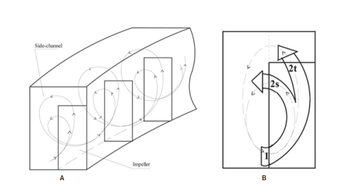
Figure 10a: Spiral flow course [23] Figure 10b: Impeller and Side channel dimensions [23]
The improved model considered the tip (β2), side (β2s) and inlet (β1) angles since a part of the fluid flowing leaves at the tip of the impeller and the other part of the fluid leaves at the side as indicated in figure 10. The CFX software was used to compare the efficiency of the pump with radial blades of different β2s at the tip of the blade and β1 for the same β2. They confirmed that the side-blade angle has a significant effect on the performance of the side channel pump. The FLUENT software was applied in the examination of the flow of the fluid in this kind of pump by [27, 28]. The experimental results corroborated the CFD analysis. They also used a one-dimensional method to describe the energy transfer inside the regenerative pump and estimate the influence of the geometry of the blade on the efficiency of the pump.
The performance of the regenerative pump was examined by Karanth et al. [29] numerically with the help of CFD. They studied the complex nature of the flow of fluid inside the regenerative pump. It was discussed that the number of impeller blades had a great significant on the performance of the pump. The head performance of the pump appreciates with the increase in the number of blades. Following the works of [29] the CFD was also applied by Maity et al. [30] to simulate the flow of fluids in regenerative pumps. It was established from their work that the pressure head loss can be minimized by curving the outlet flow domain as indicated in figure 11.
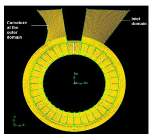
Figure 11: Regenerative Pump model displaying the curvature in the outlet domain [30]
It was indicated that there is a high rotating stalling flow at the outlet of the pump because of the reduction of the area. This effect enhances the static and total pressure across the pump. Hence, the curvature in turn increases the net pressure head by reducing the vortex flow as in shown in figure 12.
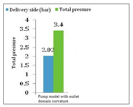
Figure 12: Bar diagram showing the total pressure for the Pump model with outlet domain curvature [30]
They also ended that, the net pressure is significantly enhanced by locating the blades on either side of the impeller by offsetting. Moreover, the net pressure is also affected by varying the number of blades on either side of the impeller. Fleder [31] numerically and experimentally examined the effects of the geometry of the blade on industrial side channel pumps in 2012. Two different impeller blade profiles were developed using ANSYS CFX 13.0 and subjected to investigations as shown in figures 13 and 14.
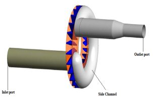
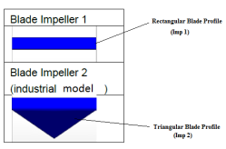
Figure 13: Design of the Side Channel Pump [31]Figure 14: Impeller Blade Profiles [31]
He concluded his work after comparison of the computational and experimental results. The experimental validation was done with a rotational speed of 750 rpm. The Imp 1 depicted good accordance both numerically and experimentally. Meanwhile, Imp 2 recorded a faster head rise because of the higher circulation frequency. This, in turn produces a greater multi-stage influence as depicted in figure 15.
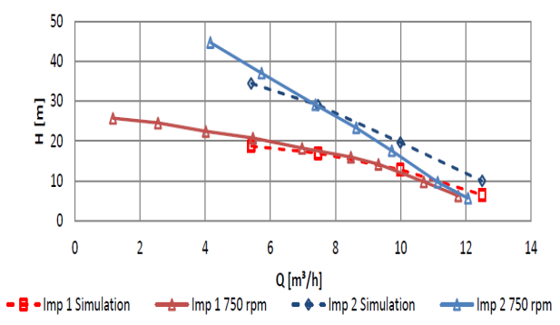
Figure 15: Assessment of the pressure head performance of the simulated and experimental results for Imp 1 and Imp 2[31]
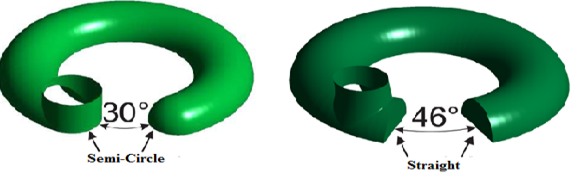
In addition, Fleder again with Bohle [32] carried out advanced studies to improve the performance of the side channel pump. In this paper, they extended their scope not only to cover the blade profile. The impeller diameter, the size of the gap, interrupter size, side channel height and the shape of the side channel were the main parameters considered. Variation of the height of the side channel, h, the width of the blade, w and the length of the blade, l, were applied to two different pump models in figure 15.
Pump Model A Pump Model A
Impeller Diameter = 150 mm Impeller Diameter = 160 mm
Gap Size s, = 0.2 mmGap Size s, = 0.4 mm
Interrupter size = 300Interrupter size = 460
Side Channel height, h = 35 mmSide Channel height, h = 40 mm
Shape of Side Channel = semi-circleShape of Side Channel = Straight
Figure 16: Variations in the pump models A and B [32]
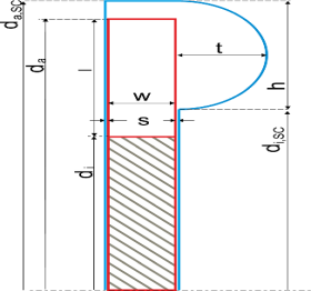
Figure 17: Parameters of the Side Channel Pump [32]
The ICEM software was applied to develop the computational models which were meshed using the structured hexahedral multi-blocks grids. They chose k-w-SST profile to assess the flow fluctuations. It was gathered that the efficiency of the pump is dependent on the ratio of the side channel height, h to the blade length, l. Furthermore, sharper pressure head features and meaningfully greater efficiencies are achieved with a gap reduction of the pump.
The work done by [21, 31, 32] on the influence of the blade angle motivated Nejadrajabali et al.[4] in 2016 also to analyze the pattern of the flow and the improvement of the efficiency of the pump by modifying the geometry of the blades. Their focus was on the effect of the variations of the angle of the blade, β numerically on the efficiency of the regenerative pump such as the side channel pump. The investigations were carried out using two sets of impellers i.e. (the symmetric blade angles and asymmetric blades angles). The symmetric blade angles were designed with the same inlet and outlet angles of ±10o, ±30o and ±50o whiles the asymmetric blade angles were also designed with the inlet set to 0o and different outlet angles ranging from ±10o to ±50o as illustrated in figure 18.
Forward/backward β1,2 = ±10o Forward/backward β1,2 = ±30o Forward/backward β1,2 = ±50o
- Symmetric blades with equal inlet β1 and outlet β2 angles
Forward/backward β2 = ±10o Forward/backward β2 = ±30o Forward/backward β2 = ±50o
- Asymmetric blades with inlet β1 = 0o
Figure 18: Geometrical designs of impellers [4]
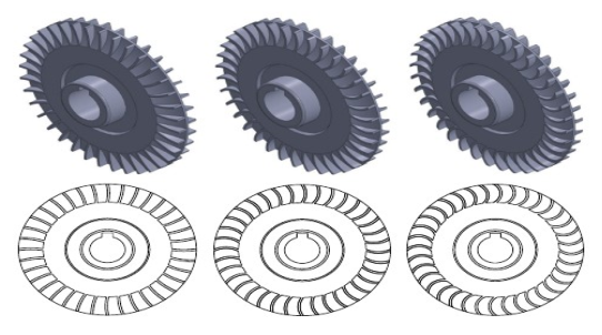
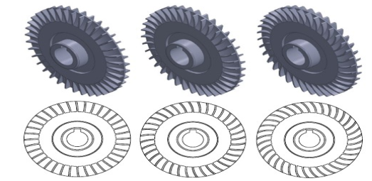
These geometrical designs were well enhanced with the application of the CFX software using the Reynolds decomposition to evaluate the complete 3D Reynolds-averaged Navier-Stokes equations. It was pointed out after the numerical simulations that, the forward symmetric blade angles compared with the other models recorded higher coefficients of heads and displayed a better performance. Recently, Zhang together with his colleagues [33] improved the head pressure performance of the side channel pump by varying the suction side blade angles from 00 to 300 as indicated in figures 19 and 20.
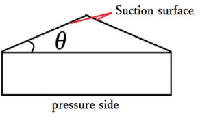
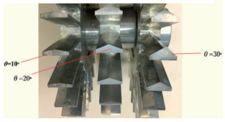
Figure 19: Cross-sectional area of the blade [33]
Figure 20: The impeller with various suction side blade profile
angles indicating θ = 100, θ = 200 and θ = 300 [33]
The CFX 14.5 commercial software was used to simulate the turbulence based on the k-w SST model. After experimentally comparing the results with the numerical simulations, it was recognized that the head performance appreciates with increasing suction side blade angles within a certain range. Even though the impeller blade profile with suction angle 300 recorded the optimal head performance, there was no significant advancement in the efficiency of the side channel pump. The regenerative pump (side channel pump) records efficiencies lesser than other types of pumps like the axial and centrifugal pumps. BÓ§hle et al. [34] lately attempted to improve the efficiency of the side channel pump by using the direct method in the context of the CFD simulations to calculate the massive losses which are associated with the various kinds of internal flow patterns of the fluid. The second law of thermodynamics was main physical principle applied in the estimation of the internal losses due to the flow patterns. According to Spurk and Aksel’s [35] proposal expressed in equation 10, the specific entropy s is a state variable agreeing with the second law of thermodynamics appreciates in all real and irreversible mechanical process in the case of turbomachinery.
 (12)
(12)
Where  = density of the fluid
s = specific entropy
u = velocity component in x – direction
v = velocity component in y – direction
w = velocity component in z – direction
x = x – coordinate
y = y – coordinate
z = z – coordinate
 = heat flux density vector
 = Dissipation
 = local dissipation by heat transfer
After the applications of three different models ( i.e. k-ϵ model, k-ω model and the k-ω -SST model) to calculate and locate the coefficient of the losses, they remarked that the k-ϵ model and k-ω model predicts estimates regions of higher coefficient of losses matched to the k-ω-SST model.
4.0 Conclusion
Though there have been several investigations into the theory of the flow principle of the fluid and variation of the geometry of the impeller and side channel, t
Cite This Work
To export a reference to this article please select a referencing stye below:
Related Services
View all


DMCA / Removal Request
If you are the original writer of this essay and no longer wish to have your work published on UKEssays.com then please click the following link to email our support team:
Request essay removal