Development of a UAV for Team Purpose
| ✅ Paper Type: Free Essay | ✅ Subject: Engineering |
| ✅ Wordcount: 1723 words | ✅ Published: 31 Aug 2017 |
Career Episode 3
CE 3.1 Introduction
During my final year of my Bachelor’s Degree in Electronics and Communication Engineering I made a project known as ‘Loon Copter’. This was a group project as it held a lot of importance in my career. It was completed in the allocated 6 months’ semester duration of my 8th i.e. final semester of my engineering. I completed my bachelor’s degree in engineering from Medi – Caps Institute of Science & Technology, Indore, India. My project guide was Prof. Sachin Puntambekar.
CE 3.2 Background
The primary need for this project is for the development of a UAV (unmanned aerial vehicle) which can be used for collaborative teaming purposes. The main intension behind configuration of this loon copter was to develop a UAV suitable for operations in dangerous situations like in forests or urban areas. They are mostly termed as MAV i.e. micro air vehicle. To keep the replacement cost low, the overall cost and complexity of the MAV should be kept low. Thus, components used by remote control flight hobbyists should be accessible for commercial off-the-shelf (COTS) should be the area of target. It is a cost-effective project with future scope.
CE 3.3
The basic ideas behind this project was to make one that could be either purchased or can be built in-house. For adding new feature and functionality I had to undergo surveys that could help find out the unmet needs and that can be added to the drone. So, from my survey I decided upon a drone that is not only waterproof but that can be submerged into the water and function there. The idea was inspiring as it was creative and innovative. There has been a development on waterproof drones that could land in water with the help of air floatation devices but homemade DIY drone that could go underwater was something new.
CE 3.4
Loon copter is a multi-mode vehicle which was named after a diving duck in Michigan that has the ability of traditional exploration vehicle for rescue and research work like:
1. on land: it can hold sensors that are below water’s surface and it is buoyant.
2. in air: it can hover over large areas like traditional drones.
3. underwater: it can replace the remotely operated underwater vehicles i.e. ORVs.
The objective and aim behind this project is that using the combination of aerial, underwater and on surface in a single drone that would help to develop new possibilities. Due to its size and its feature of underwater use it can travel large distance in short span of time when compared to submarines. It also has the feature to enable sensor loitering over large area of interest to hover upon as a multi-copter when compared to a winged aircraft.
CE 3.5
For the development of this loon copter I had to start with various research work and had to look at the problem statements. I started by undergoing various literature review from various engineering technology magazines and from the internet. Then my duties as a team leader, further involved diving the entire project into various parts and designing of its structure and work flow so that I could assign it accordingly to my team mates. I had to divide the project in parts along with assigning time slot for it so that the whole project is completed on time. The later part involved deciding upon the component requirement based on its precision to work and its ability.
Then preparation of schematic diagram for the hardware had to be done so that I could start with the implementation of the hardware outer structure based on the layout designed for the PCB i.e. printed circuit board. I had to look at all the safety rules and regulation and take proper measures when needed as being a team leader. And then it involved the final software coding part so that the project comes alive. At the end, it ended with a preparation of a small presentation along with detailed description of the project in the report.
CE 3.6 Professional Engineering Activity
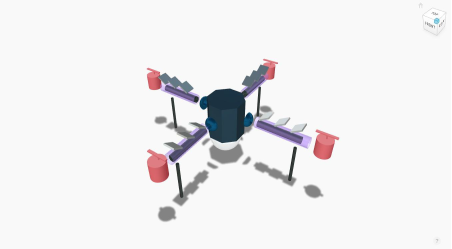
After involving in research on various loon copters, I involved myself in designing rationale of the 3D model of loon copter. It generally uses a design that makes use of an open-air mount for electronics systems. A watertight box had to be installed in the electronic system so that the quad can be submergible in water. In my project, I bought an outdoor surge box which was used as the watertight box for the exterior frame of the quadcopter. It was suitable for my system due to its large volume that was enough to hold the flight controller along with the mounts for the arms along with being light enough in terms of weight for the flight.
The box can be designed in customized form to house electronics in the outdoor environment such that it has gaskets that are surrounded on the outer side of the box. This helps to open and close as per the need and requirement to the interiors of the box along with keeping it watertight at the time of flight or submersion.
Below Diagram shows the 3D model of my project loon copter.
CE 3.7
The next step involved designing of the arm which was made up of ½ inch PVC piping that are connecting the watertight electric housing box to the rotors and the flight motors. PVC was chosen as it is light in weight and strong and can be waterproofed by applying PVC cement. And the wires can pass through them as they are hollow.
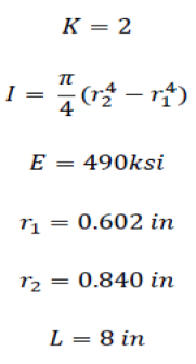
The main issue with the arms is the buckling force at the PVC tube at its hub connection point. It is calculated based on the following formula:
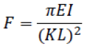
They are fixed at the connection point and the motors will be used to apply the force at the end, and using the following formula the buckling force is calculated to be 5440 lbf.
CE 3.8
The next stage was about selecting the propeller and for that the load that the quadcopter will lift had to be considered and was the main concern. For my project the all up weight (AUW) would be approx. 2.5kg i.e. 5.5 lbs. considering the safety factor and versatility of the quadcopter, it should be able to lift double the AUW. Thus, propeller was designed to lift at least ½ the AUW. For this the most convenient was to use long propeller with slow spinning rate. It involved a lot of trial and error methods in terms of the size and pitch.
The later process was the selection of the motor that would run the whole system. It was selected based on the weight and the type of propeller and bearing in mind the AUW of the quadcopter. So, looking at the calculation of 2.5kg AUW and 12 x 3.5 prop, a minimal 708kv/motor was required to lift at least 5kg of weight. And with this criterion, I found a motor that could be used for this process that was Aero sky performance brushless multi-rotor motor MC2217 of 800KV.
CE 3.8
After choosing the right components based on its requirement and looking at various calculations, I then started with working on the wiring and the connection of the hardware structure of the quadcopter. The wiring diagram can be seen below.
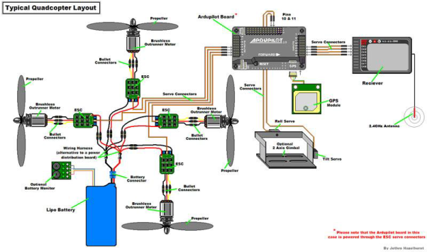
It can be said that the drone was designed and implemented using this wiring schematic diagram and it was such that it weighs 8 pounds and the motors and propellers were purchased within the assigned budget. Also, a ballast was constructed to increase its natural buoyancy from -1.5lbs to +3lbs of the craft and it can be adjusted to -2lbs. The arms could yield 5000 times higher to the expected max. load which was much higher than that was required. The deflecting arms wouldn’t have any effect on the propellers too.
CE 3.9
Therefore, after its complete design and structure it self-stabilized with the help of arrays of sensors integrated on it. The camera attached and mounted at the top of it are used to provide surveillance of the terrain and the loon copter attains an appropriate lift. The remote controller is used to give commands to the copter so that it can work and function as per the user requirements. The areas that are in-accessible to humans physically can be reached using this loon copter and it will provide a real-time audio-video transmission.
CE 3.10
There were certain difficulties I faced while executing this project like first was to stabilize the flight, when I used an aluminum frame there was no stability and the frame didn’t absorb the vibrations of the motor. So, to overcome that problem I used PVC. The other problem faced was with the weight of the frame. Due to the use of wooden frame, more power was required to lift such heavy weight. So, for that I made use of powerful motors with the velocity of 980KV and 18000rpm approx. so they could easily lift the whole structure. The third problem that occurred during this project was the concern of power supply. As the motor that was used was more powerful so it would in the end require high power for execution and for that regular batteries would not be sufficient. Therefore, I made use of lithium polymer battery also known as LiPo battery that was fulfil my requirement of battery that would provide 2000-2200 mAh current rating approximately.
CE 3.11 Summary
It can be further extended to monitor hazardous parameters like overheat or gas leakage. One can apply SMS technology to send commands for it to function. It can be used to have a feature like it can be expanded to control the air and mobility of air power roles and for cross governmental cooperation. These are few examples.
Overall, after this project I learned to manage a team and how to handle tough situations. I had to coordinate with my project guide as well as the team mates. I had to keep a balance of work and keep into account all the progress that was made. I applied a lot of my engineering knowledge into this project and in return I also gained relevant knowledge though rigorous and intensive research and analysis on various components and related topics. It was a great learning experience. At the end a detailed project report was made on my project.
Cite This Work
To export a reference to this article please select a referencing stye below:
Related Services
View all


DMCA / Removal Request
If you are the original writer of this essay and no longer wish to have your work published on UKEssays.com then please click the following link to email our support team:
Request essay removal