The Design of a Voltmeter-Ammeter Using PIC Microcontroller
| ✅ Paper Type: Free Essay | ✅ Subject: Engineering |
| ✅ Wordcount: 977 words | ✅ Published: 30 Aug 2017 |
In electrical or electronic engineering, the voltmeter and ammeter are important devices and are used to measure current and voltage. These devices are very important as they give you an understanding of what is happening in an electrical or electronic circuit. Without these devices we wouldn’t be able to determine numerical values of voltage and current therefore we wouldn’t have the ability to solve electrical problems.
The main objective of this project is to gain experience with the design process covering all aspects of the design process.
Two software packages will be used to orchestrate the design process of the circuit and complete build of the project. These packages are OrCAD PCB Editor and Auto-Cad Inventor.
This will entail everything from the designing and building of the circuit, using the software package OrCAD PCB Editor the design process will begin designing the circuit by applying all the necessary components for the Volt-Ammeter.
The circuit will be built using a PIC microcontroller with a built in LCD screen which will illuminate the voltage and current readings.
The second stage will be using the design package AutoCAD Inventor. This is a design software that is used to design the casing of the product with all the specifications needed to give the product the compact finish needed to complete the product before presenting it to the customer.
A volt-ammeter is the project designed for Napier University so the students can benefit from an easy to use product having the ability to test, measure and do calculations when measuring voltage and current.
The finished product must have certain specifications which will make the device portable, easy to use and compact and also making the device durable so the students can use the device safely without encountering any problems or difficulties.
The budget for the project has to be under £40 per unit so the university can benefit from the finished designed product.
1.2.1 Functionality
Electrical measurement devices are used to digitally calculate electrical quantities. Two of the more common quantities are voltage and current.
A volt-ammeter is perfect as an addition to any electronic projects like battery chargers or power supplies where it is a necessity to monitor current and voltage consumption. Regarding this project, a PIC16F876A microcontroller will be used to interface the LCD screen.
1.2.2 Engineering requirements
The volt-ammeter device will be designed to measure an output voltage ranging from 0-70v/0-500V with a resolution of 100mV which will be carrying a current between 0-10A with a resolution of 10mA.
The volt-ammeter will have a step up and step down button for added calibration to make it possible to measure voltages over 70V and to measure current over 10A.
A PIC 16F876A microcontroller will be used in the volt-ammeter. The microcontroller will have a built in analogue to digital controller with a blue/green illuminated LCD display.
|
Voltage Supply |
6V-30V |
|
Voltage Input |
0-70V / 0-500V |
|
Voltage Resolution |
100 mV |
|
Current Consumption |
100mA – LCD Backlight |
|
Current Input |
0-10A (or more) |
|
Current Resolution |
|
Figure 1- performance table
1.2.3 Additional Specifications
Because the Volt-Ammeter is designed with very few External components it will be made possible to meet the specifications fitting all the components onto a small PCB making it possible for the finished product to be a very handy and portable meter.
The meter will be able to produce readings that are accurate, this is due to the calibrated software that is built in and additionally the 1%metal film resistors.
There is only one supply voltage needed and this can be acquired by using any mains power supply. The completed meter will only consume 10mA from the backlight of the LCD screen when switched on and 3mA when not in use.
When the 10 Ohm resistor is disconnected the backlight of the LCD display will be switched off
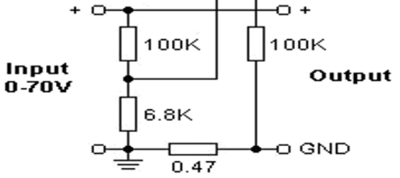
Figure 2 – external components
1.2.5 Casing Specifications
- The casing needs to be compact so it can be hand held for ease of use.
- Compact with all wires concealed to illustrate a safe finished product.
- Waterproof for protection from electrocution and to prevent damage to components.
- Additional fittings for PCB placement.
- LCD Screen placement on front of casing. (central)
- CMOS FLASH-based 8-bit microcontroller.
- Performance speed of 200 Nano Seconds.
- Flash Program Memory.
- Program Memory 14 KB.
- 368 RAM Bytes.
- 2 x 8-bit, 1 x 16-bit Timers.
- Analogue to Digital Converter- 5 channel, 10-bit.
- 2 Comparators.
- Temperature Range -40 to 125 degrees Celsius.
Figure 3 – PIC Microcontroller
2.1.1 Voltmeter
when measuring voltage between two points in an electrical or electronic circuit a certain device must be used. This device is a voltmeter and is intended to measure either direct current (DC) or alternating current (AC).
There are two types of voltmeter, these devices are either analogue voltmeters or digital voltmeters.
The analogue meter has a current meter in series with a high resistance. This high resistance is needed otherwise the circuit being tested will be disturbed due to a significant amount of current being drawn.
A digital voltmeter displays numerical values; these values can range of 1000v to 3000v and can increase in powers of 10.
2.1.2 Ammeter
An ammeter is the instrument needed to measure electrical current that flows through a circuit. The ampere or amp is the unit of measure for current.
Conclusion
The writing and design of this project has been made possible due to the applied theories and practical skills that I have learnt and administered in integrated circuit design.
The knowledge I have gained has given me the skills to produce design and construct operating systems that are capable of performing practical tasks. Because of these skills it has given me the confidence to write design and produce this project which is titled ‘The Design of a Volt-Ammeter using PIC microcontroller’.
http://pic-microcontroller.com/voltmeter-ammeter-using-pic-microcontroller/
http://www.microchip.com/wwwproducts/en/PIC16F876A
http://whatis.techtarget.com/definition/voltmeter
http://study.com/academy/lesson/what-is-an-ammeter-definition-function-quiz.html
Cite This Work
To export a reference to this article please select a referencing stye below:
Related Services
View all


DMCA / Removal Request
If you are the original writer of this essay and no longer wish to have your work published on UKEssays.com then please click the following link to email our support team:
Request essay removal