Conveyor Based Sorting System: Overview Detection Approach
| ✅ Paper Type: Free Essay | ✅ Subject: Engineering |
| ✅ Wordcount: 2344 words | ✅ Published: 31 Aug 2017 |
Abstract:
When the objects move on the conveyor belt, they fall into the receptacle at the end of the belt. Once the bin is filled the conveyor belt must stop in order not to overfill the bin. To make this possible we could use some sensors in the receptacle and link the belt and the weighing scale (on which the bin is placed) through programming so that when the receptacle reaches to certain weight the belt automatically stops. Some of the weighing sensors and level detectors are discussed in this report to reach a conclusion to decide the right method of approach to stop the overflowing of objects into the bin.
Weight measuring sensors:
There are various types of sensors used in measuring the weight of objects with different sizes and shapes. Strain gauges, load cells (of different types and shapes) and force sensors are some of the measuring sensors which are used in electronically weight measuring equipment.
These sensors are installed in devices that measures the changes of force applied on them or the change of pressure on the particular spot of object or even the tension of the object.
Our aim is to choose an approach for an overflow detection system when at the end of conveyor belt, the coloured objects are collected in a large bin. That is placed on the weighing device which accurately measures the weight of the bin/receptacle with the objects, and once it’s filled the conveyor belt/PLC stops and prevents the bins from overflowing.
In this concept, to measure the weight, we could use different sensors like load cells of different types and strain gauges.
1. Strain gauges:
It is a device with varying resistance when certain amount of force or pressure, tension and weight is applied. It also converts them into measurable electrical resistance. This is the reason most of the load cells and electronically weight measuring scales are based on this strain gauge principle. Strain is a physical property of a material when it undergoes external displacement or deformation. Thus, this types of sensors can be used to measure both expansion and contraction.
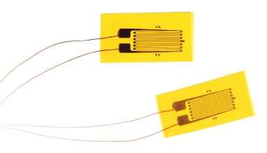 Strain gauge model
The image1 above shows a typical metal-foil strain gauge which is widely available in the market.
Strain gauges are mounted or glued to the surface of a solid material and when the material is compressed or stretched, the electrical resistance increases or decreases respectively.
Generally, a Wheatstone bridge is used to change the varying resistance into varying voltage as the change in resistance is relatively small when using strain gauges to measure the weight of an object.
Still, the output analogue signals are amplified further as this output signals from the Wheatstone bridge is still smaller when compared to the PLC in the design which is expected to be around 0 to 10V.
The picture below shows the typical circuit of a strain gauge connected to the Wheatstone bridge (also known as Quarter bridge strain gauge circuit). The resulting output voltage is always a millivolt unit.
Depending on the use of whole structure, the number of strain gauges connected to the Wheatstone bridge varies.
Let’s assume that, the weighing device below the receptacle/bin is fitted with the strain gauge, then every time an object falls into the bin causes a change in the tension in the gauge resulting a change in resistance.
The picture2 below shows the typical assembly of strain gauge and Wheatstone bridge.
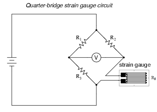
The output voltage is normally measured using a voltmeter connected in circuit but can also be calculated using the following equation,
The receptacle is assumed to be placed on the weighing scale which tends to be wider and a bit spacious which makes, using a single strain gauge to cover the whole space is not ideal. To improve the accuracy, we could use more than one strain gauge to cover the space on weighing scale.
Advantages of strain gauge:
Using strain gauges in the design have some pros and cons. Some of the advantages include,
- In a strain gauge, there are no moving parts but only a strip
- It is very small and easy to use on a piece of solid object
- When it comes to cost, it’s very inexpensive and easily available
- In our design, using more than one strain gauge to cover the weighing scale improves the accuracy.
Disadvantages of strain gauge:
- The strain gauges need to be calibrated for it to work per desired design
- Overloading can be a problem; the strain gauges measure the stress on the scale in micro strain. Therefore, if the bin is slightly overfilled or even the load in it is beyond the limit then the results may be degraded. Just for a reference the limit normally be ±3000 micro strain.
- If the wires of the get wet or not protected against humidity, the resulting electrical resistance might lead to parasitic results. If the design was to be open and wires are exposed to spillage which may cause errors in the result.
2. Load cells:
A load cell is a device which uses one or more strain gauges in its design to measure the force applied on the surface and change it into an electrical signal. Load cells can be in various types like hydraulic, pneumatic load cells, piezoelectric and capacitive load cells. Since it uses more strain gauges in the design which increases the accuracy of the model.
Generally, Copper (Cu) and Nickel (Ni) alloys are used in the construction of the strain gauge load cells. When the length changes in the electrical conductor due to the stress applied on the free end, the resistance of electrical conductor also changes. in strain gauge load cells, use of Cu and Ni in this model is beneficial as the applied strain is virtually proportional to the change in resistance. This change in resistance is used to measure the strain applied if its connected to appropriate measuring circuit.
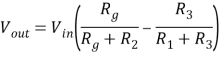
This is a model image3 of a binocular beam strain gauge load cell which is more than one strain gauge and when there’s stress applied on the free end, stretch in the gauge causes change in electrical resistance and thus the weight of the bin is measured.
Hydraulic load cells are also known as force balance devices, one of the types of load cells which measures the weight of an object as pressure changes in internal filling fluid. As the force or pressure changes on the loading surface, pressure of the fluid inside the cell is also increases.
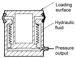
The image4 above is a simple design of hydraulic load cell with the hydraulic fluid inside.
Advantages of load cells
Some of the advantages and disadvantages of the load cells are discussed below.
- It comes in various shapes and sizes like rugged shape and it’s in compact construction
- Load cells doesn’t have any moving parts inside the structural design
- Since they have wide surface area which also has wide range of measurement
- Since our design (assumed concept) has a static weighing machine below the receptacle, load cells can be used and they also be used in dynamic loading
- Load cells are highly accurate since the loading surface is solid and wide area which covers the loading surface of the weighing machine.
Disadvantages of load cells
- Compared to the strain gauges, load cells are solid and larger in size and shape
- As they have a solid structure and of different shapes, it may be hard to mount on any surface
- Just like a strain gauge model, calibration with these load cells is also essential in the process of measuring the weight of the objects fall into the receptacle
- They are slightly expensive and a very costly signal conditioning
3.Force sensor resistor:
Force sensor resistor which is also known as force sensitive resistor (FSR), is a resistor material where the resistance changes whenever the force or pressure changes on the surface. When compared to the strain gauges and load cells, FSR measures the compressing force or weight differently by directly correlating the strain of the beam to the applied force on the surface.
Piezo-resistive force sensor is one of these types of force sensors. It is a strip of layers with different form of inks which can detect the applied force or stress on the material where the strip is attached to.
The image5 blow shows the simple construction of a special FSR called Piezo resistive force sensor.
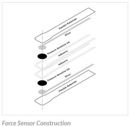
Every time each object falls into the receptacle or bin, the force is applied on the surface of the weighing scale which then compresses two layers of pressure sensitive ink within the flexible and adhesive substrate layers in the sensor. This pressure creates the tension in the layers converts them into electrical signals which then can be calibrated just like the load cells with the help of programming with engineering force units.
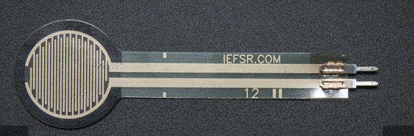
This is an image6 of a Round Force Sensitive Resistor (Model: Interlink 402 with ½ the diameter sensing region from the measuring surface).
Advantages of Force resistive sensor
- FSR are generally very small and thin (about 0.2mm) and very flexible in construction which allows them for unobtrusive measurements to be taken in practical application
- These types of sensors are programable and customizable per the specification of the design concept
- These sensors are very cost effective and readily available in the market
- They are also inexpensive in programming or signal conditioning in electronics
- They only consume very low power and its light weight as its very thin in structure
Disadvantages
- In measuring weight or pressure applied these sensors are very inaccurate with the results like ±5% of full scale than a load cell
- They are calibrated by us, the users, which can lead to manual errors whereas load cells are programmed by the manufacturers if ordered directly
Different approach than programming:
Level detectors:
Other than using just weight sensors to detect the weight of the receptacle and stop the overflow when the objects are filled, we could also use some level detectors at the top of the bin to detect whether the objects have reached the top while the object fall into the bin from the conveyor belt.
For an effective way of stopping the overflow, mix use of both level detectors and weight sensors would improve the accuracy to stop the overflow. A typical level detector is used to detect once the material is at the determined point within the receptacle which is also known as Point Level Sensor (PLS).
These sensors can be used to detect the levels of the objects at high, low and intermediate levels of the bin. These also must be programmed or calibrated to the desired level in the bin for the accurate results.
Image7 below shows the typical model of Rod pointing level sensor which can be used to measure the liquid, slurry materials, powders or solid objects levels in a vessel.
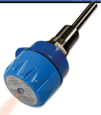
This sensor has a self-built alarm and LED indicator which can be activated when the objects in the vessel reaches the desired indication point. It has no moving parts in the assembly and since its simple design which makes it easily mountable on any part of the receptacle to our desired level.
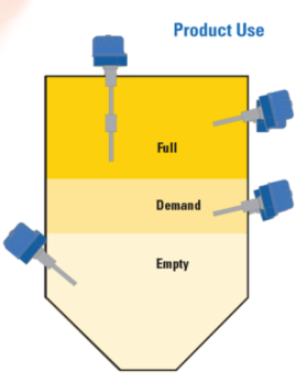
This image8 shows the ways of mounting the sensors in various levels of the bin.
Conclusion:
Weighing scale and conveyor belt are linked through the program so that when the receptacle is filled and desired weight is reached, which then signals the conveyor belt to stop filling the bins. This is the assumed concept for which we were using weighting sensors to detect the weight of the bin and stop overflowing. For this we can’t just use programming to stop the overflow we would also need some additional sensor to detect the weight or the maximum level that the objects can reach.
Therefore, to achieve the higher accuracy we could use both level detecting sensors and weighing sensors in the concept to stop the overflow of objects.
Load cells are preferable means of sensing the weight of the receptacle to stop the overflow. Load cells are the sensors with the solid base where more than one strain gauges are mounted which improves the accuracy of measuring the weight of the bin.
If we use strain gauges to measure the weight, we would be using more and more strain gauges to cover the wide area where the bin is placed. This could increase the cost of the project and using more gauges may result to find the average value between them to detect the weight which not be accurate. Using more strain gauges may also result in massive circuits and lots of wires hanging all over the places. So, if there’s any faults in the circuits, it may be hard to find it.
Load cells are the right choice since they have no moving parts in them which makes them more easily mounted under the receptacles.
Use of both load cells and Level detectors in the design may benefit the approach to stop the overflow of the objects from the receptacle.
References:
Appmeas.co.uk. (2017). Load Cells | Force Sensors | Force Transducers | Load Measurement. [online] Available at: http://www.appmeas.co.uk/load-cells-and-force-sensors.html?gclid=CLSe34mxzNICFQsR0wodQu8Nmw [Accessed 12 Mar. 2017].
Binocular load cell. (2017). [image] Available at: http://www.instrumentationengineers.org/2013/07/load-cell-working-types-advantages-and.html [Accessed 10 Mar. 2017].
En.wikipedia.org. (2017). Wheatstone bridge. [online] Available at: https://en.wikipedia.org/wiki/Wheatstone_bridge [Accessed 12 Mar. 2017].
Force sensor Construction. (2017). [image] Available at: https://www.tekscan.com/resources/ebook/load-cell-vs-force-sensor [Accessed 12 Mar. 2017].
Hydraulic load cell model. (2017). [image] Available at: http://www.instrumentationengineers.org/2013/07/load-cell-working-types-advantages-and.html [Accessed 10 Mar. 2017].
Level detector. (2017). [image] Available at: http://www.blueleveltechnologies.com/products/modelVHS.html [Accessed 12 Mar. 2017].
Round FSR model 402. (2017). [image] Available at: https://www.adafruit.com/product/166 [Accessed 12 Mar. 2017].
Strain gauge. (2017). [image] Available at: https://www.slideshare.net/mac899/strain-gauge-23842407 [Accessed 9 Mar. 2017].
Tekscan. (2017). Load Cell Vs. Force Sensor. [online] Available at: https://www.tekscan.com/resources/ebook/load-cell-vs-force-sensor [Accessed 12 Mar. 2017].
Us, C. (2017). Load cell working, types advantages and disadvantages. [online] Instrumentation Engineering. Available at: http://www.instrumentationengineers.org/2013/07/load-cell-working-types-advantages-and.html [Accessed 12 Mar. 2017].
Cite This Work
To export a reference to this article please select a referencing stye below:
Related Services
View all


DMCA / Removal Request
If you are the original writer of this essay and no longer wish to have your work published on UKEssays.com then please click the following link to email our support team:
Request essay removal