Chemical Engineering and Clean Technology : New Reactor Types
| ✅ Paper Type: Free Essay | ✅ Subject: Engineering |
| ✅ Wordcount: 2319 words | ✅ Published: 23 Sep 2019 |
CHEMICAL ENGINEERING AND CLEAN TECHNOLOGY WORKSHOP:
NEW REACTOR TYPES
The chemical sector has long been seen being socially dangerous and “dirty”. Increased global competition has forced industry to look at green routes for achieving efficient manufacturing processes. Since the 21st century, significant amounts of research have been carried out into the development of sustainable and environmentally friendly techniques for chemical synthesis, with the main goal being the reduction of waste generated by the chemical industry. [1]
The reactor is often seen and described as the “heart” of chemical processes. Downstream processes are a function of the reactor performance, particularly in such features as degree of control, selectivity and heat and mass transfer. Moreover, the upstream processes can be regarded as a series of steps with the only objective to get the reactants to the best possible condition for input to the reactor.
Flow chemistry and continuous processing can offer many ways to make synthesis a more sustainable procedure. These technologies provide significant improvements in mixing and heat management, scalability, energy efficiency, waste generation, safety, access to a wider range of reaction conditions, and unique potentials in heterogeneous catalysis and multistep synthesis. [2]
In this regard, a type of reactor that is becoming increasingly of interest is the membrane flow reactor. In this apparatus, the membrane could have multiple functionalities, it can work as a separator for recovering reaction products in situ, or for catalyst recovery. As for most other separation techniques the key feature of membrane reactors is their ability to take reactions to completion by continuous product removal.
Many types of membrane reactors have been developed and tested in the last two decades. One form of membrane reactor which is attracting attention, even if proposed in 2003, is the tubular inorganic catalytic membrane (TICM) described by Centi et al. Its applications range from refinery uses to environmental protection. Lower pressure operation, allowed by the possibility of putting the catalyst into the membrane pores, combined with better three-phase contact in comparison with other reactors, leads to higher selectivity and yield. The reduction of nitrates or nitrites in water using a tubular membrane reactor configuration (Fig. 1), was also described by Centi et al. (2003). Furthermore, their study showed that the membranes could be regenerated intermittently by removing them from the reactor, calcining and pre-reducing with helium/hydrogen, and once reintroduced, the membranes were essentially immaculate.
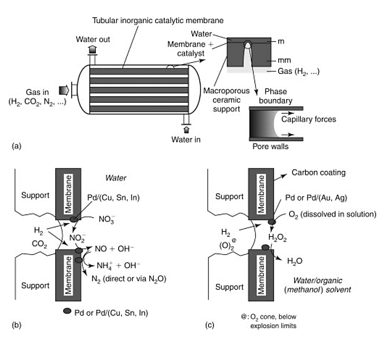
Fig 1. Configuration of a tubular inorganic catalytic membrane reactor module (Centi et al., 2003) [3]
Among membrane reactors, gas–liquid–solid (GLS) and liquid–solid (LS) type slurry reactors are widely used in the chemical, fine chemical and pharmaceutical industries. Applications include hydrogenation, condensation, esterification and enzymatic conversion processes. In these slurry processes the catalysts must be recovered externally from the reaction mixture. This filtration step is not beneficial for the process, it does often lead to catalyst attrition and deactivation, as well as operation and handling problems. Moreover, attrition of catalyst particles can cause loss of catalyst particles and emissions to the environment. Inefficient use of the catalyst, combined with extensive residence time distributions, can lead to undesired by-products.
A membrane slurry reactor would be a solution to these drawbacks. In the membrane slurry reactor concept, improved control of process conditions and a more efficient use of the catalyst are guaranteed by membranes and heat exchanger tubes, which allows separation and heat transfer within the chemical reactor. A main advantage is, however, that the membrane slurry reactor can bring the use of more selective catalysts (enzymes) and subsequent selective product recovery, leading to higher conversions, reduction of the amounts of by-products and emissions and optimisation of the quality of the main product. The membrane slurry reactor therefore takes an important step towards a more sustainable, green chemical industry.
Heat exchanger tubes and hollow fibre membranes located within the reactor allow the removal of reactants and products from the system. Remarkably, the use of a membrane reactor for the enzymatic hydrolysis of casein has been reported by Trusek-Holownia (2008). [3]
A more recent work, shows the development of a scalable, safe and sustainable thin-layer membrane reactor for homogenous Cu(I)/TEMPO alcohol oxidations and heterogeneous Pd-catalysed hydrogenations by Mo et al. This is particularly interesting since among numerous pharmaceutical transformations, gas–liquid reactions (e.g. aerobic oxidation and hydrogenation) show appealing atom economy in comparison to other chemical transformations. Furthermore, the overall availability of gaseous reagents and simple downstream separation make gas–liquid reactions potential green chemistry processes. However, concerns of process efficiency, scalability and safety of gas–liquid systems limit their use for pharmaceutical applications, and this becomes even more challenging when heterogeneous catalysts are involved. The safety profiles are though significantly improved when gas-liquid reactions are carried out in continuous flow reactors, where there is no high-pressured gas in the headspace and the reactor volume is contained. In addition, the increased interfacial area per volume in flow reactors accelerates multiphase mass transfer rates. The continuous reactor developed by Mo et al uses a Teflon AF membrane, inserted between two sheets of thin-layer carbon cloth (Fig. 2a), which enables superior gas–liquid mass transfer performance. The carbon cloth layer works as a heterogeneous catalyst support, making this reactor design applicable for heterogeneous catalytic gas–liquid reactions. Additionally, most of the gas is consumed during the reaction, removing the need for recycle and enhancing the safety of the process by minimizing the amount of gas required. Another important feature to underline is that the membrane reactor is also stackable, allowing for scale-up. [4]
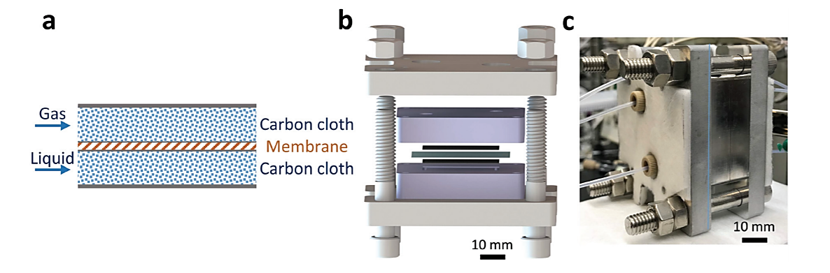
Fig. 2 (a) Gas–liquid membrane reactor schematics. (b) Exploded-view CAD drawing of the gas–liquid membrane reactor. Two thin black layers are carbon cloth; the blue layer is a Teflon AF membrane. (c) Photograph of assembled single-layer membrane reactor. [4]
The main advantage of using a Teflon AF membrane is related to its high permeability to the only gas phase, which enables the separation of the two different phases while allowing gas to diffuse through the membrane into the liquid phase. Moreover, the design of the reactor was planned to minimize the thickness of the combined assembly (carbon cloth: 300 µm and Teflon AF membrane: 40 µm) in order to improve the mass transfer phenomena. In addition, this reactor can handle high pressure operation (tested up to 3.1 MPa), improving the solubility of H2 in the organic solvent and therefore intensifying the hydrogenation process. For the study reported, the membrane reactor (Fig. 2b and c) was fabricated out of aluminium, due to the inferior cost of the material. To achieve higher chemical compatibilities, the reactor could also be coated with perfluoro alkoxy alkane (PFA) or fabricated out of stainless steel. The internal temperature is controlled by cartridge heaters combined with a proportional–integral–derivative (PID) temperature controller. For the system maintenance, it is necessary to rinse the reactor liquid side with appropriate solvent and the gas side with nitrogen, before the beginning of a new procedure. Once the reagents are introduced into the reactor, the gas side must be pressurized while maintaining a low (∼150 kPa) transmembrane pressure with the back-pressure regulator (BPR) on the liquid section, which is required to prevent the passage of the gas through the BPR and the disruption of the membrane.
Pt and Pd heterogeneous catalysts appeared both to be good alternatives for hydrogenations reactions, but experiments proved the former to be too aggressive, leading to the formation of by-products, while Pd showed a better selectivity towards the desired product. Once optimized the reaction conditions, the membrane reactor has been used to carry out numerous hydrogenations with different substrates, proving itself to be efficient. [4]
Aerobic oxidation reactions could be an attractive alternative to conventional approaches employing stoichiometric oxidants. However, the concrete use of aerobic oxidation in large-scale synthesis advances safety concerns, i.e. the formation of explosive mixtures (flammable organic solvents in oxygen). Micro-structured flow reactors are currently used for aerobic oxidations, because of the intrinsic safety of their microchannels. However, the explosive mixture is still present. Tube-in-tube membrane reactors show great potential to avoid the formation of this dangerous mixtures, but still have inherent scalability issues for large-scale synthesis. Implementing the thin-layer membrane reactor designed by Mo et al. offers the opportunity to make aerobic oxidation reactions both safe and scalable for industrial applications. Instead of using a catalyst-embedded carbon cloth layer, virgin carbon cloth was installed in the membrane reactor, along with the same Teflon AF membrane to accommodate the homogeneous catalytic (Cu/TEMPO) aerobic oxidation. Meanwhile, the Teflon AF membrane separates the oxygen and organic solvent to circumvent the formation of explosive mixtures. Many substrates were examined in the membrane reactor with optimized conditions, and all products were achieved in excellent yields.
The residence times required to reach full conversion were around 1 min, significantly shorter than the several-hour reaction times required under batch conditions. Furthermore, the capability to handle high pressures in the membrane reactor would intensify this reaction by orders of magnitude compared to batch processing.
In trickle-bed or packed-bed reactors the scale-up process is particularly problematic due to the change in multiphase hydrodynamics, mass and heat transfer properties within different scales. The simplified fluid hydrodynamics in the thin-layer membrane reactor allows for straightforward scale-up with a stackable design. The stackable design maintains a fixed heat and mass transfer distance (carbon cloth thickness) while increasing the reactor size laterally and in parallel, leading to preserved heat and mass transfer advantages of the single-layer membrane reactor while meeting the required productivity. As shown in Fig. 3, the main channels of a 3-layer stacked membrane reactor distribute or collect gas streams and liquid streams into or from each layer. [4]
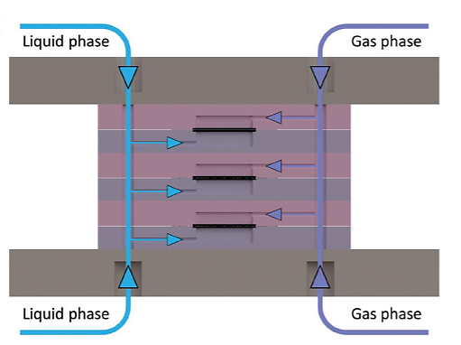
Fig 3. Cross-section of the inlet channels in a 3-layer stacked membrane reactor with blue arrows indicating the liquid flow and purple arrows indicating the gas flow. The outlet channels collect flow from each layer with reversed arrow directions.
In conclusion membrane reactors properties make them in general an interesting type of reactors to work with and on in the future. For example, their high surface to volume ratio guarantees higher reaction rates, reaction and separation can occur in one step reducing the overall cost and the presence of less stagnant zones gives a good catalyst reactivation, therefore membrane reactors are to consider as a sustainable and greener option compared to other reactor types currently used in industry.
The Teflon AF membrane reactor is of certain interest since both the membrane design and the guidelines for safe operation of oxygenation reactions provided by Mo et al. could potentially speed up the implementation of oxygen and hydrogen as cheap, green reagents in industrial chemical applications. In comparison to other membrane reactors the thin layer design maximized mass transfer in gas-liquid systems and simplified the multiphase hydrodynamics for liable reactor performance and scale-up. Moreover, optimizing the carbon cloth thickness according to the reaction kinetics balanced the trade-off between reactor manufacturing cost and productivity. [4]
REFERENCES
[1] C. Wiles and P. Watts, Green Chem., 2012, 14, 38-54
[2] S. Newman and K. Jensen, Green Chemistry, 2013, 15, 1456
[3] D. Reay, C. Ramshaw and A. Harvey, Process Intensification, 2013, 121-204
[4] Y. Mo, J. Imbrogno, H. Zhang and K. Jensen, Green Chemistry, 2018, 20, 3867-3874
Cite This Work
To export a reference to this article please select a referencing stye below:
Related Services
View all


DMCA / Removal Request
If you are the original writer of this essay and no longer wish to have your work published on UKEssays.com then please click the following link to email our support team:
Request essay removal