Basic Implementation of OpenStack
| ✅ Paper Type: Free Essay | ✅ Subject: Engineering |
| ✅ Wordcount: 1033 words | ✅ Published: 31 Aug 2017 |
3.1 Basic Installation
In this project Open stack was installed through pack stack that is a repository module, help to implement various parts of OpenStack. It represents a utility which facilitates the deployment on multiple nodes for different components of OpenStack via SSH. This requires multiple pre-installed servers. In our case it is CentOS. There are two ways to work with packsack. As follows.
Packstack Interactively: the Interactive way is the user commands are run at same time as he gives the command. The user enters the command
Packstack Non-Interactively: the Non-Interactive way is the way when the user updates the file known as answer file. Enables and customize the options in the answer file, that customize file is run for OpenStack.
In this project, Non interactive is used to install pack stack. Answer file will be applied on our controller node, as all service will work in controller node. The answer file is a file that pack stack takes in order to take decisions that we put in the script, that we want to setup in OpenStack. Services will be enabled such as Glance, Cinder, Nova, Horizon, Swift, Ceilometer, and Heat as shown in FIG 3.1 and FIG 3.2
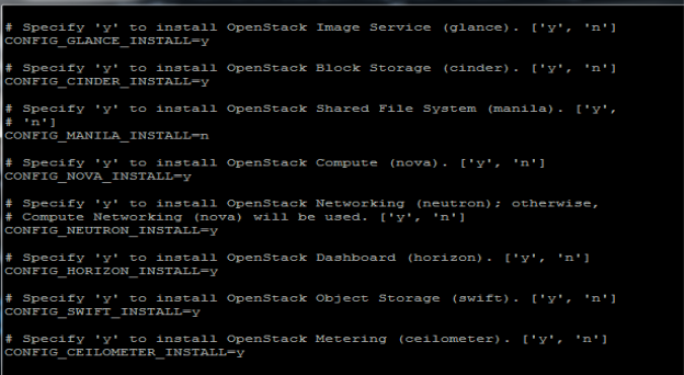 FIG.3.1 (Answer File with services)
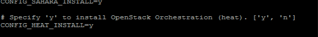
FIG.3.2 (Answer File with heat services enabled)
Answer file also consists of IP addresses of the three main nodes, Compute, Controller, and Neutron. Compute node, in this project the three nodes are on one single node as shown in FIG.3.3. All these nodes should be interconnected.
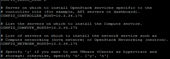
FIG.3.3(Answer File with all IP address)
Moreover, the answer file also consists of keystone authentication user and password in plain text as well as the token that is discussed in the previous chapter as well. This token allows the user to the services that user is allowed to get access.
After Answer file is modified the file is run through pack stack through the following in FIG3.4
.

FIG.3.4(Run Answer File over pack stack )
Then access the dashboard through GUI as it is successfully installed after as shown in FIG 3.5
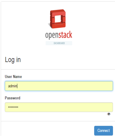
FIG.3.5 (User Authentication by open stack (Keystone))
As discussed before keystone plays the authentication role, known as identity service as well. It ask for username and password when this authentication is done the keystone provides the token to the user that consist of the services that are been allowed to the user to access
3.2 Implantation Projects and Other services
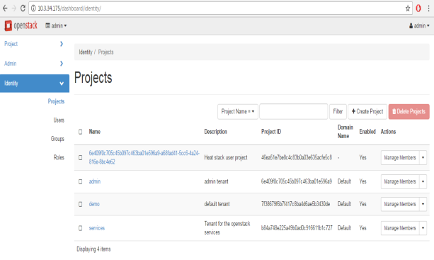
FIG.3.2 (Different projects of OpenStack)
After getting access we can see different projects. OpenStack can deal with different project at a time. Every project has different members as shown is FIG 3.3.A member can be a part of two different projects.
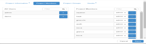
FIG.3.3 (Project Members)
The cinder volume is the block storage that is provided to the user related to different projects. This is a logical storage to every user that can be attached or detached to the user. This memory can be reused for another user as user finished his work and memory is deleted. The user can be given different memory chunk according to the use.
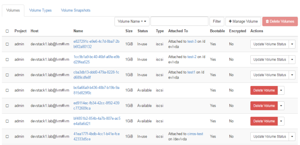
FIG.3.4 (OpenStack Volumes attached to different users)
As in FIG.3.4 different volumes are attached to different users for the project “admin”, their IDs are showing as their name with size of their volume, with the contrast of their instances those are attached to.
The next service will be glance service in OpenStack picture. Glance is the storage service that is responsible for keeping images for different instances. All the instances will run through the image file that will be stored in Glance. There can be more than one image but in our scenario its just one image as shown in FIG.3.5

FIG.3.5 (Openstack Glance service)
3.3 Networks and Router
The network is the neutron service of the OpenStack that provides the interfaces for different user and services to connect with each other. Since OpenStack deals with cloud computing with private and public cloud, therefore there will be a big role to play for NATing. As shown in FIG 3.6a. OpenStack not only provides compute and data storage service but also understands the role of networks to connect these services. In the following FIG it clearly shows the instances those are connected to a private cloud, on one side of the router with all private IP addresses, will be nated on the other side of the router through public cloud.
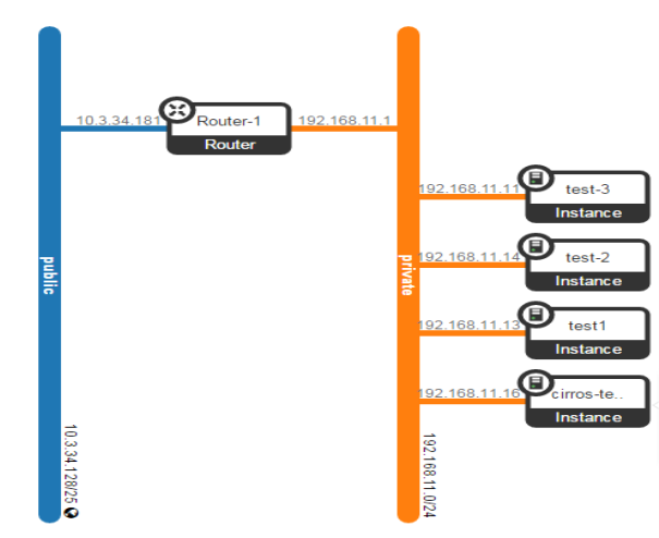
FIG.3.6a (OpenStack Network)
In other words, these private instances can also be accessed through external network. In this unit, this will be explained further.
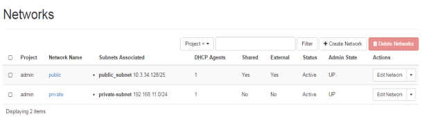 FIG.3.6b (OpenStack Network)
As shown in FIG.3.6b private and public IP addresses are shown that will be used for nating. Furthermore, router is also available is OpenStack networking services that not only help in nating but also manages the external and internal networks of OpenStack services.
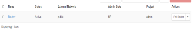
FIG.3.7 (Openstack Router)
Unlike other vendor routers, it does not need so much of command configuration, which is the best part of OpenStack router. It is capable of doing all basic required routing functions. These all capabilities plays great role in OpenStack. As shown in FIG.3.7, FIG.3.8 and FIG.3.9 some of the routing capabilities.
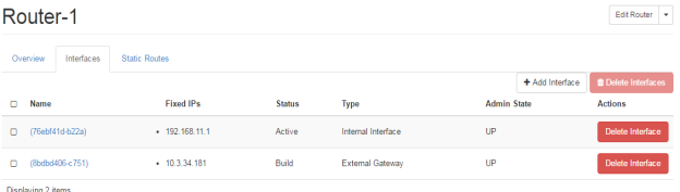 FIG.3.8 (Openstack Router)
In the FIG.3.6 you can easily identify the router ports, where the ports are assigned with the IP addresses, these are the IP addresses from the private and public cloud as shown in FIG.3.4. Moreover, this clarifies that NATing has done by the router, where one port is towards external gateway of the network. This is towards the internet in our scenario. The port is defined on internal or private network.
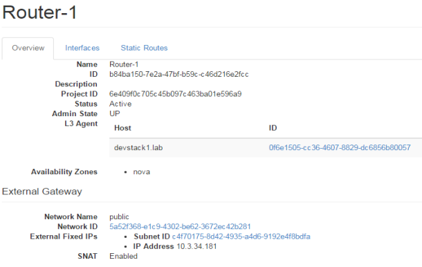
FIG.3.9 (Openstack Router)
Public IP addresses are defined as floating IP for the project that needs to be accessed from external network. In the given FIG 3.10 following floating public IP addresses are shown that are for the admin projects, where instances are also defined with their tagged names, as well as their status.
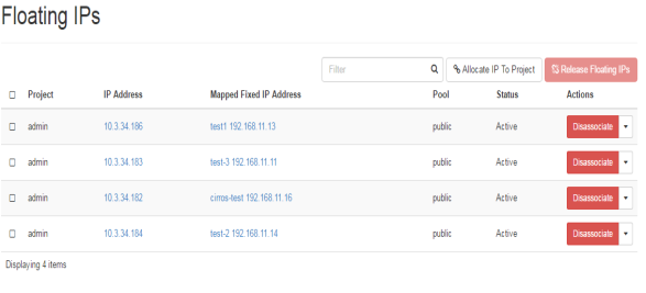 FIG.3.10 (Floating IP addresses)
For any network it very important to have systematic way of deployments and organize the way of understanding the deployment of any network. This cannot be possible without a graphical representation of network topology diagram as shown in FIG.3.11, as well as in FIG.3.6a in the beginning.
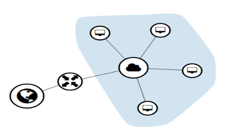
FIG.3.11 (Floating IP addresses)
Cite This Work
To export a reference to this article please select a referencing stye below:
Related Services
View all


DMCA / Removal Request
If you are the original writer of this essay and no longer wish to have your work published on UKEssays.com then please click the following link to email our support team:
Request essay removal