Automatic Fire Alarm System (A-FAS) Design
| ✅ Paper Type: Free Essay | ✅ Subject: Engineering |
| ✅ Wordcount: 4112 words | ✅ Published: 30 Aug 2017 |
ABSTRACT
The safety of the environment and individuals is monitored and maintained by the important role fire alarm systems play. Although, the usability of many of the existing fire alarm systems is known by the users, however, they are produced with high cost thus not reasonable for the low-income users. The main objective of this project is to design a prototype of an automatic fire alarm system (A-FAS) with low cost. The A-FAS designed in this project contains two systems, the detection system and the alarm system. The detection system operates as the fire detector and consists of a smoke detector, heat detector and an emergency switch as a manual call point. This paper discusses the design and implementation of a microcontroller based fire alarm system. The detectors are placed in different zones and any signal from any detector at any zone will activate the alarm system. The alarm system consists of LEDs, LCD notification, buzzer and text message notifications. Furthermore, the system is fitted with sensors at different zones to identify the presence of individuals, this feature aids the monitoring process of the system. The entire system is controlled by a microcontroller which is programmed using Arduino compiler. Upon completion of the prototype, the A-FAS detects smoke or any rise in temperature sensed by the detectors. Finally, when any of the sensors are triggered, the buzzer operates and the system sends a text message to the saved number. With the development of A-FAS, the safety of individuals and surroundings will be increased as the low cost of the system will promote users of all income levels to have one at their place or home.
INTRODUCTION
An overheated electrical appliance, a burning splinter or a burning cigarette or just about any of these can trigger a fire. Moreover, the presence of nylon settings and a sofa set which emanate poisonous gases if on fire, will render people helpless in a couple of minutes, before even realizing what is happening.
ADT Security Service and the Chubb Alarm are the well-recognized companies that deal with security systems and have been the innovative leaders in security systems. The products offered by these companies vary from intruder alarms to highly sophisticated fire alarm systems. Furthermore, the systems built by these companies are high in cost and require a scheduled maintenance to be carried out by the company’s specified authorities.
Based upon the current existing high cost fire alarm systems that are available in the market, an automatic fire alarm system with low cost has been developed. The A-FAS consists of two subsystems; detection system and alarm system.
The A-FAS detection system has smoke detecting capabilities as it incorporates an optical smoke detector. Moreover, it is interfaced with heat detector and an emergency switch. The system features counting capabilities based on infrared sensors to ease the determination of individuals in case of emergency.
The A-FAS alarm system is associated with the detection system to ease the process of alarming individuals in the event of fire. The alarm system consists of LED and LCD notifications displaying the location of the fire. A buzzer is also incorporated in the system. The system sends text message alerts as it incorporates a GSM module.
Finally, the main part of the A-FAS that controls the entire operation is the microcontroller. This thesis describes the design and operation of a microcontroller based fire alarm system that could contribute to saving lives and reduce property losses with low cost.
- Aim
The main purpose of this project is to design and prototype an automatic fire alarm system (A-FAS) with effective and competitive usage and can be produced at a low cost. This system is designed to be easy to operate by any user and is user friendly.
The A-FAS is also been designed using minimum hardware at the lower level of processing. The system is not restricted to the mentioned inputs and outputs, however, can be altered per customer needs without having to design a new system.
- Problem Identification
The complexity of the existing fire alarm system in the market nowadays is too high in terms of design and structure. Due to the complexity of the system, regular preventive maintenance is required to be carried out to make sure that the system is operating well. Moreover, the scheduled maintenance adds to the cost of the using the system. Therefore, the proposed fire alarm system is designed with a low cost and can be used by any user for safety purposes.
- Project Objectives
There are several objectives that are required to be accomplished in developing the A-FAS to determine the purpose and the direction of this project. This project aims to achieve the following objectives:
- To design a low-cost microcontroller based fire alarm system.
- To develop a prototype of the fire alarm system using smoke detector, heat detector, emergency switch and infrared sensors as inputs to the system. Moreover, using LEDs, LCD display, buzzer and text messages as outputs to the system.
- To develop a prototype with the capability of customizing the system to meet with the customer requirements with regards to the inputs and outputs, without having to redesign a new system.
- To develop an automatic fire alarm system to safeguard the user and their surroundings, while being user friendly to accommodate the need of the masses.
- Project Scope
To achieve the above objectives, the project needs to be implemented as below:
- The heart of the fire alarm system is to be a microcontroller to control the entire operations involved.
- The fire alarm system is to count the number of individuals present in the locations where the infrared modules are installed.
- Capable of displaying the source of the alarm on the LCD display.
- Capable of sending SMS notifications via GSM module interfaced in the system.
- Project limitation
Since the project is interfaced with a GSM module that needs a SIM card to send SMS notifications and thus the system is limited to the amount of credit available on the SIM. Moreover, the system includes infrared sensors that are used to count the number of people entering and exiting the zone and thus to make the system more sensitive and receive only the infrared radiation from the correct source, the infrared modules need to be placed with a minimum distance of 2 meters.
Furthermore, to receive live data from the sensors to produce visual output to the user in terms of if any sensor is disconnected from the system, the system is required to have personalized sensors.
- System Overview
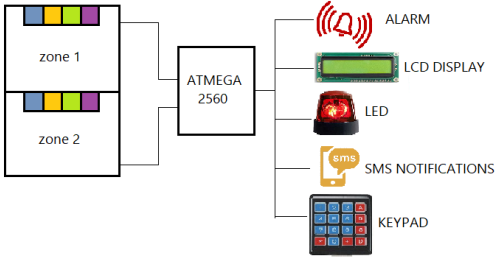 Figure 1.1 defines the inputs and outputs interfaced to the microcontroller device. The A-FAS has the features of interfacing additional inputs and outputs based on customer needs.
|
Color |
Type of sensor |
|
|
Infrared sensors |
|
|
Smoke detector |
|
|
Hear detector |
|
|
Emergency switch |


The A-FAS works in a loop checking all the input sources and acting accordingly. The smoke detector, hear detector and the emergency switch transmit a signal to the microcontroller once triggered, this notifies the microcontroller to hazard the surroundings via the output devices. A keypad is added in the system to allow the user to interface and monitor the system.
The Atmega2560 microcontroller acts as the heart of the Fire Alarm System which controls the entire system. The signals being received from the sensors are being compared by the Atmega2560 to either hazard the surroundings for the existence of fire or to hazard the surroundings for the presence of a fault in the system.
Moreover, the system can alert the surroundings via a buzzer and LED notifications as well as SMS notifications once the Atmega2560 microcontroller receives signals that there is fire present in one of the zones.
- Thesis structure
This thesis is divided into six chapters. The first chapter explains the problem statement, objectives, scopes and limitations of the project. The second chapter in this thesis is the project’s literature review, which is based on the detection components of the A-FAS, the ATmega2560 and a comparison between microcontrollers and microprocessors. Moreover, this chapter contains summary of several available inventories software available in today’s market and previous projects developed by engineers.
Furthermore, chapter three describes the phases involved in the development of the A-FAS. There are four phases involved in the production of the fire alarm system which include the research phase, the designing phase, development phase and the analysis phase. Chapter four of this thesis discusses the system design process involved and the hardware and software development. Moreover, chapter five explains the results of the system development of the A-FAS and its analysis based on the system operation and functions.
Finally, chapter six concludes the project and the recommendation suggestions for the continuity of the project and future work. The sixth chapter aids to the continuity of the project by other individuals interested as they can refer to it to develop the system.
CHAPTER II
LITERATURE REVIEW
As mentioned earlier in the previous chapter, cost factor plays a very important role in this project. Subsequently, to design a system with the objectives mentioned above requires research and studies that are described in this chapter. This chapter will include three subtopics, previous case study on fire alarm systems, hardware and software studies.
- Fire Alarm System: Related Work
According to Bao Minzhong, Jianmei, Niihau Xiao and Wang [1], the function of the fire alarm system is to detect fire at an early stage providing sufficient time to produce high reliable judgment results. If the fire alarm system nosedives to notify the user in the presence of fire for the user to take appropriate measures, the system fails as alarm systems should cause the operator to respond. Moreover, Brown Campbell [2] suggested that for a system not to fail, it must require positive feedback from the operator.
Nur Abd Aziz [3] proposed a fire alarm system consisting of three sensors, thermistor hear sensor, infrared sensors and infrared smoke sensors. The thermistor heat sensor was used to detect the rate at which temperature rises and high temperatures. The infrared sensors were used for intruder alarms to detect the presence or any motion, acting as a burglar alarm system. The infrared smoke sensors were used to identify fire in its early stages or smoldering. In the presence of fire, the water sprinklers are automatically switched on and the burglary alarm is activated. The known catalysts for fire is smoke, flame and heat but only smoke and smoke sensors have been applied and emphasized. Furthermore, when a fire occurs, the highly sensitive motion sensors will respond to normal environmental vibration which could be caused by moving cars or planes overhead.
Furthermore, Chew and Ing Ming [4] proposed a similar system consisting of smoke detector, heat detector and a burglar alarm. In the event of smoke or a rise in the temperature, the system sends a signal to the microcontroller which in return operates a buzzer. Moreover, the microcontroller operates an auto redialing telephone programmed with specific number. This system. Moreover, the system is implemented with photo-electric sensor and inductive proximity switches. The photo-electric sensor is activated when transmitter cannot send light to the receiver. The inductive proximity switch is normally used for metal detection and activates when a metal is detected in the system. Once any of the sensors is activated, the microcontroller will sound the buzzer and flash LEDs. Chew and Ing Ming categorized the system proposed for industrial purposed. The complexity of this system contributes to the inability of installing such system at homes or offices.
- Detection components of the Fire alarm system
Sensors are types of transducers that responds to a type of energy by producing another type of energy signal, usually electric [5]. Some of the sensors available include acoustic, biological, chemical and electromagnetic. These are used in many applications and are heavily used in the medicine industry and robotics as a source of detection components. The detection components of the A-FAS consist of smoke sensors, heat sensors and infrared sensors.
- Smoke Sensors
Smoke detectors are devices designed to detect a fire while it is in its early stages or smoldering, duplicating the sense of smell. These devices have gained a wide usage in the residential and life safety applications. There is no debate that smoke detectors is the single most effective method of reducing fire damages and death. 90% to 95% of fire deaths occur in residential buildings (NZFS, 1993), targeting this will help accomplish the most cost-effective results.
Studies of various types of smoke detectors, in particular photoelectric and ionization smoke detectors, illustrates that, one type of detector will be expected to perform better than the other, depending on the source of the smoke. Natarianni (1993) concludes that in flaming wood crib fires, the ionization smoke detectors activate before the photoelectric detectors. This conclusion is from simulated fires in hospital patient rooms. However, most importantly, both detectors activated before threatening the patient’s life.
Moreover, a series of full-scale tests of smoke detectors installed in corridors and bedrooms of residential areas was conducted by Kennedy et al (1978). They concluded that inadequate warning in smoldering fires were often produced by ionization detectors. Subsequently, reducing the time available for escape once activated and the escape routes may be smoked-logged.
Photoelectric smoke detectors contain a light emitting device, most commonly a light-emitting diode(LED), a smoke chamber and a photosensitive device that produced a monitored current from receiving light directly from the light source. The intensity of tech light reaching the photosensitive device is reduced by the smoke that enters the chamber. A drop in the intensity below a certain level causes a drop in the current produced by the photosensitive device, which is detected by the sensor control circuitry. Dropping the current below a preset threshold results in triggering the smoke alarm.
Table 2.1 summarizes the advantages and disadvantages of photoelectric smoke detectors. The complete specification of the smoke detector used in the A-FAS can be obtained in Appendix A.
Table 2.1: Advantages & disadvantages of photoelectric smoke detector [6].
|
Advantages |
Disadvantages |
|
|
- Heat Sensors
A heat sensor detects abnormal rate of temperature rise or high temperatures. There are numbers of various heat detectors available in the market, which include:
- Thermistor.
- Thermocouple.
- Resistance temperature device.
- Diode based temperature sensor.
There are certain features to consider while choosing the best heat sensor for any use. These features are summarized in table 2.2.
Table 2.2 Features of various heat sensors [7].
|
Thermocouple |
RTD |
THERMISTOR |
SEMICONDUCTOR |
|
High accuracy and repeatability. |
Fair linearity |
Poor linearity |
Linearity: 1oC Accuracy: 1oC |
|
Needs cold junction compensation |
Requires excitation |
Requires excitation |
Requires excitation |
|
Widest Range: -148oC to +2300 oC |
Widest Range: -200oC to +850 oC |
Widest Range: 0 oC to +100 oC |
Widest Range: -55oC to +150 oC |
|
Low voltage output |
Low cost |
High sensitivity |
10mV/K,20mV/K Typical output |
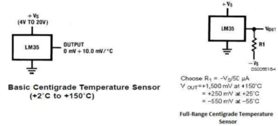
The LM35 temperature sensor are precision integrated circuit temperature sensors, which will be used to develop the A-FAS. This sensor is fully rated from -55 °C to +150 °C and with the linear scale factor of 10mV/°C. It operates from 4 to 30 V, has less than 60 µA drain current and has low self-heating (0.08 °C in still air). The control circuitry or the interfacing of LM35 is easy due to the low output impedance, linear output and precise inherent calibration. The LM35 series is available in hermetic TO transistor packages, while the LM35C, LM35CA and LM35D are available in TO-92 transistor package. The LM35D is also available in an 8-lead surface-mount small outline package and a plastic TO-220 package. [8] (Reprinted from datasheet of LM35 [8].)
The LM35 can function as a basic centigrade temperature sensor sense temperature between +2 oC and +150 oC and can function as a full -range centigrade temperature sensor sensing temperature between -55 oC to +150 oC. Figure 2.1 illustrates the circuitry for using the sensor for both functions, where +Vs is the voltage supplied to the sensor. Adjusting the output voltage of the sensor enables the temperature to be obtained in degree centigrade.

- Infrared Sensors:
There are many sensors available for obstacle detection such as infrared sensors, ultrasonic sensors, camera and laser based sensor system (LIDAR). In this thesis, infrared sensors are used to accomplish the task of counting the numbers of individuals in the placed installed.
Low cost with accuracy is one of the main objectives of this project, hence infrared sensors were selected for the design. These sensors are widely used for measuring distances and obstacle detection and have faster response time than ultrasonic sensors [10]. Moreover, power consumption of the infrared sensors is lower than that of ultrasonic sensors [11]. Infrared sensors are categorized as diffuse reflection sensors and retro-reflective sensors. The latter is mainly used in harsh environment conditions and has a larger detection range than the diffuse reflective sensors [12]. Infrared sensors utilize a light sensor to detect a selective light wavelength in the spectrum. When an object obstructs the sensor, the light from the LED is broken by the object and the signal is not received by the receiver.
- ATmega2560 Microcontroller
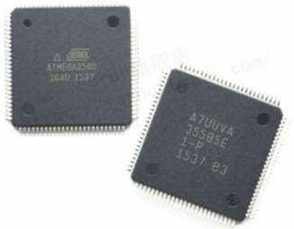
As defined by James L. Atonakos [13], microcontrollers are souped-up microprocessors with built-in features such as RAM, ROM, A/D, Interval timers and parallel input and output ports. Atmega2560 (figure 2.2), is a powerful flash microcontroller that contains many features in a 100-pin package. The datasheet of the ATmega2560 is attached in Appendix B.

The definition of a flash microcontroller is that it can be programmed and erased instantly without the usage of ultra-violet light. The Atmega2560 is an 8-bit microcontroller with a powerful execution of instructions in a single clock cycle leading to the achievement of 1 MIPS per MHz, allowing the designer to optimize power consumption vs processing speed [14]. The internal architecture of the microcontroller is shown in figure 2.3.
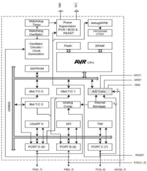

The central processing unit (CPU) is the brain of the microcontroller that controls the execution of the program, therefore able to access memories, handle interrupts and perform calculations. The microcontroller unit (MCU) consists of 256K bytes of in-system flash, 4K bytes EEPROM and 8K bytes of SRAM, which are used for memory. Other features include [14]:
- 86 programmable input and output ports.
- Ultra-low power consumption in active and power down mode.
- flexible timer/counters with compare modes and internal and external interrupts.
- Code protection facility, which is one of the best in the industry.
- Comparison between microcontroller and microprocessor
The fact that microcontrollers may have one or two operational codes for moving data from external memory to the CPU, whereas, microprocessors have many operational codes, is the best way to exemplify the contrast between microcontrollers and microprocessors.
Microcontrollers have many types of bit handling instructions, however, microprocessors have one or two. In conclusion, the microcontroller is concerned with rapid movement of bits within the chip, whereas, microprocessors are concerned with rapid movement of codes and data from external addresses to the chip.
Microcontrollers can function as a computer with the addition of no external digital parts, however, microprocessors must have many digital parts to be operational [15].
- OrCAD
Figure 2.4 shows the OrCAD software used for circuit designing, testing and circuit analyzing. Generally, OrCAD is a software used to produce printed circuit board (PCB) layouts. The circuit was drawn onto the PCB board using OrCAD Capture, where footprints for each component was researched. The design rule check ensures that there are no errors present in the circuit.


- Arduino IDE
The Arduino IDE (Integrated development environment) is a platform application from ATmega microcontrollers. Figure 2.5 shows the Arduino version used to compiling the program. Arduino IDE is used for writing, debugging, and optimizing ATmega microcontroller applications for firmware product design. Arduino programs are written in C or C++ and the software comes with a library called wiring which makes may common outputs and inputs operations much easier.


- Fire alarm systems available in the market
There are several types of fire alarm system available in the market today. The various fire alarm systems from different developers vary in terms of implementation and functionality. Research has been carried out to investigate the technology and features used to develop each of the systems and compared them with the proposed A-FAS system. Table 2.3 concludes the results on the research, [16] [17].
Table 2.3 Manufacturers products
|
Specifications |
SECURE 6000 |
INTELLIGUARD 2900 |
|
Developer |
Chubb Alarm |
ADT Fire and Security |
|
Fire monitoring |
Available |
Available |
|
Security monitoring system |
Available |
Available |
|
Service and maintenance |
Provided |
Provided |
|
Main features |
|
|
|
Cost |
$2,055 |
$1,800 |
CHAPTER III
Methodology
This methodology chapter describes the planning and research involved in the development of the entire A-FAS system. The progress of this project was due to the division of the work in four phases; research phase, designing phase, development phase and the analysis phase.
- Introduction
The fire alarm system described in this thesis is divided in to two sections, which are the hardware and the software sections. These sections play a vital role in the effectivity and the functionalities of the system. In order to start developing the project, there are few procedures that must be considered. Thus, earlier planning is important in designing and developing the A-FAS. The related phases have been illustrated in figure 3.1.
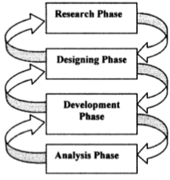

- Research phase
The first phase of this methodology deals with the system’s literature studies, research and analysis. Problem identification is included in the research phase. Moreover, the system objectives are determined by observations and theoretical information obtained from internet sources, journals, books and magazines.
During this phase, the system requirements are determined, which include the hardware and software interfacing. Furthermore, the research and analysis conducted on the existing systems available in today’s market is included in the research phase, as well as reviews on previous projects developed by organizations or individuals.
A few problems have been identified based on the current research that has been done, which include:
- Burglar alarms are combined with the fire alarms in the same system, leading to confusion and inability to identify the source of the alarm by the user.
- The systems available are designed for specific purposes, providing the user with no options of customization of the fire alarm inputs and outputs.
- The cost of the systems is too high for low income individuals to secure their lives and properties by purchasing one.
Websites and documentations were the source of reviews on analysis activities conducted in this phase. The system planning and development scheduling were then determined in this phase which suited the chosen development methodology. Upon completion of this phase, the system scopes, specifications and Gantt chart were produced.
- Designing Phase
The second phase of the system development is the designing phase. The main objective of this phase is to translate or transform the requirements and analysis obtained from the research phase into design specifications for system implementation and construction.
This phase involves a vital task for the success of the automatic fire alarm system, which is the hardware design of the system.
- Designing of the A-FAS hardware system
The A-FAS hardware design involves detection components and the microcontroller. The detections components which are the smoke detector, heat detector, infrared sensors and an emergency switch are connected to the microcontroller. The latter is the control unit identifying the source and location of the fire if any of the input detection devices is triggered. A text message will be sent and a buzzer will be activated for individuals to evacuate the premises.
- Smoke sensors
The system has been implanted using a Mercure photoelectric smoke detector. The system has the capability of being interfaced with most of the market available smoke detectors. However, to interface the smoke detector to the microcontroller, the smoke detector circuit is required to be altered. The smoke detector then sends a signal to the microcontroller in the event of emergency.
The photoelectric smoke detector used in this project is very effective and highly recommended by users, with a low cost. These devices offer high power dissipation capability and are ideally suited for hostile environments.
- Heat sensors
The LM35 temperature sensor has an output voltage which is linearly proportional to temperature in centigrade, thus the sensor is suitable for the project. The sensor draws very small amount of current which makes it very low self-heating. Figure 3.2 describes th
Cite This Work
To export a reference to this article please select a referencing stye below:
Related Services
View all


DMCA / Removal Request
If you are the original writer of this essay and no longer wish to have your work published on UKEssays.com then please click the following link to email our support team:
Request essay removal