Steps in System Design
| ✅ Paper Type: Free Essay | ✅ Subject: Computer Science |
| ✅ Wordcount: 2823 words | ✅ Published: 27 Mar 2018 |
CHAPTER 3
HIGH LEVEL DESIGN
3.0 High Level Design
The high level design discusses an overview of how a system be supposed to work and how the higher stage sections to contains the suggested answer. It would be supposed to have very less information about implementation that is no clear class descriptions and during case not even details such as data base type (relational or object) & programming language and platform.
High level design gives an overview of system flow. However, this gives more information for the user to understand the logic. Here we see the basic knowledge about the system design and architecture. Following are the issues that we see in this part which are the primary components for the design.
3.1 Design Considerations
The key design considerations of deadline constraints broadcasting in wireless network are:
- Creation of network with twenty nodes, including the base station node and its client nodes.
- Broadcasting the packets by base station to its nodes.
- Calculating all the measures and getting feedback information from all nodes for the transmission.
- According to which designing the three main scheduling policies for the broadcasting delay in the network.
- Network which does not uses network coding mechanism, designing the greedy scheduling policy.
- Network which uses the network coding mechanism for which designing the linear coding scheduling policy and pair wise XOR scheduling policy.
- Finally performance analysis is done for each scheduling policy, considering the deterministic, probabilistic arrivals of packets for asymmetric and symmetric topology.
 3.2 System Architecture of Deadline Constraints Broadcasting in Wireless Network
System Architecture of deadline constraints broadcasting in wireless network in shown in figure 3.1 System architecture is the theoretical design that describes the structural and behavioral features of a system. The description of the architecture is the official explanation of the system. That is arranged in the form that maintains interpretation concerning the structural possessions of the system. And it characterizes the system apparatus or building blocks and gives a preparation from which yield can be procured and systems are developed that are work jointly to apply in general system.
The base station will broadcast the arrival of packets using different types of systems like greedy scheduler, pair wise XOR, linear coding and feedback scheduler to the particular nodes.
Design feasible optimal policy for the broadcasting of delay in traffic. Since the base station will not having any idea regarding feedback information from all its client nodes, it cannot identify the real timely throughput established by each client node for the flow of packets. Though, with the knowledge of channel reliabilities, the base station will calculate approximately the timely throughputs by measuring the possibility that a client node gains the packet of a flow in every time gap.
There is stationary randomized scheduling policy and a positive number, which decides a schedule arbitrarily from the scheduling space where it is based on the packet coming at the creation of the period and self directed of the system history before the time interval that accomplish the system with timely throughput supplies.
A system with any coding mechanism, a designing policy aims to maximize, a policy is feasible optimal. Three different kinds of coding mechanisms, first think about a system where network coding is not been used. In each time slot, the base station will broadcast the unprocessed packet from the stream that has been produced one packet in the time interval. Deduce a few separation of flows has been produced packets at the starting of the interval the probability that client receives the packet from flow in this interval. Since the base station can make broadcasts in an interval.
The probability that client has not received the packet from flow during the first transmissions, and receives this packet when the base station broadcasts the packet from flow for the next time. Thus, classify the subjective trivial liberation chance of the broadcast of an online scheduling Greedy algorithm.
The use of pair wise XOR coding for broadcasting, the base station can either broadcast a raw packet from a flow, or it can choose to broadcast an encoded packet from flow packet from flow, the XOR of a packet from flow with a packet from flow. A client can recover the packet from flow either upon directly receiving a raw packet from flow, or upon receiving a raw packet from flow and an encoded packet. Consider a system with two streams of flow of packets that produce single packet in every interval with only individual client whose direct reliable. Assume that there are six time slots in an interval. Suppose that the base station transmits each packet three times in an interval. Thus, a system with timely throughput requirements is not possible when complex network coding is not in use. Thus system with pair wise XOR coding can achieve strictly better performance than one without network coding.
By employing linear coding in the direction to advance the performance of dissemination delay constraints flow of packets besides the unprocessed packets the base station can also transmit small packages that having linear grouping of packets from any streams of flows. The consumer can decipher all packets from the separation of streams if it receives at least packets that having linear grouping of packets from those stream of flows. If a client receives less packets having linear combination of groups cannot be decoded from those flows of packets.

Figure 3.1: System Architecture of deadline constraints broadcasting in wireless network
3.3 System Specification using Use Case Diagram
Use case diagrams are represents the typically noticeable interactions with the aim of the system will perform with the users and external systems. They are exercised to depict in what way the user can carry out the role by means of the systems and it form an important part of the progress of the method. Use case diagrams describe schedules of work, user guides, test plans and are functional all the way through the whole development progression.
Use case models use a concept known as actors to visualize what is deemed to be outside the system. The use case also describes about the exterior unit will interrelate with the system and the work that the system will need to perform.
Use case scenarios that describe how actors use the system. The actors are external factors that interact with the system. Actors are identified based on who is using the system or who will be using the system.
The actor represents the role a user plays with respect to the system. Identifying actors is an important as identifying classes, structures, attributes, associations and behavior.
3.3.1 Use Case Diagram for Deadline Constraints Broadcasting in Wireless Network
Use case Diagram of deadline constraints broadcasting in wireless network is shown in figure 3.2.

Figure 3.2: Use case Diagram of deadline constraints broadcasting in wireless network
Name of the module: deadline-constrained broadcasting in wireless network.
External users or actors: base station and client node.
Functionality of the system: functionality of the system includes adding flow and broadcasting flow. Broadcasting flow has the functions like greedy scheduler, pair wise XOR scheduler, linear scheduler and feedback scheduler.
Description of deadline-constrained broadcasting in wireless network: The use case diagram of the deadline-constrained broadcasting in wireless network shown in figure 3.3. The base station used to add flow and broadcast the flow in the network, where it can use any technique to broadcast the delay in the network like it may use non coding mechanism by using greedy scheduler policy, and coding mechanism by introducing pair wise XOR scheduler policy, linear scheduler policy and it may use feedback scheduler policy. There by base station broadcast the delay to the respective client nodes.
3.4 Data Flow Diagram for Deadline Constraints Broadcasting in Wireless Network
A data flow diagram is a graphical depiction where the data flows all the way through an information system. It is also used for the visualization of data processing that is structured design. In DFD information flows from the external source or an internal process towards the internal information store or the external information drop through is the midway course.
Level_0
The context-level or level 0 data flow diagram describes the interface between the method and external agents which operate as data sources and data sinks. Scheduled on top of the background diagram also termed as the Level 0 DFD where the system’s interfaces with the outside world are modeled merely during the data flows crossways the system edge. In the context diagram the complete system as only one process and provides no clues to its own internal group.

Figure 3.3: Level 0 Data flow diagram for deadline constraints broadcasting in wireless network
3.4.1 Data Flow Diagram for Deadline Constraints Broadcasting in Wireless Network
Level _1
The Level 1 DFD describes about the division of sub systems of the complete system and each of the sub systems deals with at least one of the data flows to or from the outside way and which together provides all of the functionality of the process. It is also recognize the internal data provisions that should there in sort of the progression to do the work and it illustrates the flow of information among the diverse parts of the procedure.


Figure 3.4: Data Flow Diagrm of Probability data flow for deadline constraints broadcasting in wireless network
Table 3.1: Transmission of packet of different flow deadline constraints broadcasting in wireless network
|
Process No. |
Subsystem Name |
Data flow to description |
|
1.0.1 |
Calculate weighted marginal delivery probability flow |
According to which the time slots are divided. |
|
1.0.2 |
Schedule flows |
Using various network coding mechanism, the flows are scheduled. |
|
1.0.3 |
Broadcast packet of flow |
Broadcast the delay of packet, reaching the node. |
3.4.2 Data Flow Diagram of XOR coding for Deadline Constraints Broadcasting in Wireless Network


Figure 3.5: Data flow diagram of XOR coding for deadline constraints broadcasting in wireless network
Table 3.2: Transmission of XOR coding for deadline constraints broadcasting in wireless network
|
Process No. |
Subsystem Name |
Data flow to description |
|
1.0.4 |
XOR packet of different flow |
Performing XOR operation for the pair of flows. |
|
1.0.5 |
Node reconstruct packet |
After XOR operation, reconstructing the packet to flow. |
|
1.0.6 |
Node reconstruct cost packet |
Measuring the distances among the nodes and detecting the arrival of packet across the traffic in the network. |
 3.4.3 Data Flow Diagram of Linear coding for Deadline Constraints Broadcasting in Wireless Network
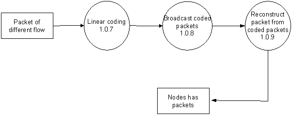
Figure 3.6: Data flow diagram of linear coding for deadline constraints broadcasting in wireless network
Table 3.3: Transmission of linear coding for deadline constraints broadcasting in wireless network
|
Process No. |
Subsystem Name |
Data flow to description |
|
1.0.7 |
Linear coding |
Combining the flows of packets. |
|
1.0.8 |
Broadcast coded packets |
Broadcasting the delay of packets. |
|
1.0.9 |
Reconstruct packet from coded packets |
Obtaining the original flows from the coded packets. |
3.4.4 Data Flow Diagram of Broadcasting packets for Deadline Constraints Broadcasting in Wireless Network


Figure 3.7: Data flow diagram of broadcast packet for deadline constraints broadcasting in wireless network
Table 3.4: Transmission of broadcast packet for deadline constraints broadcasting in wireless network
|
Process No. |
Subsystem Name |
Data flow to description |
|
1.0.10 |
Broadcast packet |
Simply Broadcasting the packets to the client nodes by the base station. |
|
1.0.11 |
Get feedback |
Once broadcasting getting the feedback information for all transmission of packets. |
|
1.0.12 |
Schedule flow |
Broadcasting the packets according to the scheduling rules. |
|
1.0.13 |
Broadcast packet |
Broadcast the delay in arrival of packets by the base station. |
3.5 Sequence diagram for Deadline Constraints Broadcasting in Wireless Network
Sequence diagrams display interactions between the objects from temporal standpoint. A sequence diagram represents an interaction between objects that focuses on the message. An object is represented by rectangle and its lifeline is represented by a vertical bar line.
Initialization Flow
The sequence diagram of the initial flow is shown in figure 3.8.
STEP 1: The admin directs the main to create the new network and the network is created.
STEP 2: The new base station is created by the network by main through admin.
STEP 3: The new node is created by the network by main through admin.
STEP 4: The network is shown by network through the main and admin.


Figure 3.8: Sequence diagram for Initialization Flow
Greedy Scheduler
The sequence diagram of the greedy scheduler is shown in figure 3.9.
STEP 1: The admin add the flow by base station and starts broadcasting of packets.
STEP 2: The new base station is starts scheduling of the packet flow to greedy scheduler.
STEP 3: The greedy scheduler sends back the packet flow once it done coding.
STEP 4: Then broadcasting takes place from base station to node.


Figure 3.9: Sequence diagram for Greedy Scheduler
Linear coding scheduler
The sequence diagram of the linear coding scheduler is shown in figure 3.10.
STEP 1: The admin add the flow by base station and starts broadcasting of packets.
STEP 2: The new base station is starts scheduling of the packet flow to linear coding scheduler.
STEP 3: The linear coding scheduler sends back the packet flow once it done coding.
STEP 4: Then broadcasting takes place from base station to node.


Figure 3.10: Sequence diagram for Linear coding scheduler
Feedback scheduler
The sequence diagram of the feedback scheduler is shown in figure 3.11.
STEP 1: The admin add the flow by base station and starts broadcasting of packets.
STEP 2: The new base station is starts scheduling of the packet flow to feedback scheduler.
STEP 3: The feedback scheduler sends back the packet flow once it done coding.
STEP 4: Then broadcasting takes place from base station to node.


Figure 3.11: Sequence diagram for Feedback scheduler
Pair wise XOR scheduler
The sequence diagram of the pair wise XOR scheduler is shown in figure 3.12.
STEP 1: The admin add the flow by base station and starts broadcasting of packets.
STEP 2: The new base station is starts scheduling of the packet flow to pair wise XOR scheduler.
STEP 3: The feedback scheduler sends back the packet flow once it done coding.
STEP 4: Then broadcasting takes place from base station to node.


Figure 3.12: Sequence diagram for Pair-wise XOR scheduler
3.6 Classes Designed for the system
The class diagram is the major structural block of objective leaning modeling. Class diagrams can be used for information modeling. The classes in a class diagram shows both the major objects and communications in the systems and the classes exist to program. It is used both for general conceptual modeling, for systematic applications, detailed modeling, and for converting the models into encoding rules. In the diagram classes are presented with boxes shapes which have three parts.
- The upper part of box has the name of the class
- The middle part contains the attributes of the class
- The bottom part of box produces the processes or functions the class has to perform
The design of a system has the number of classes that are recognized and joined together in the class diagram which assists to find out the relations among objects. The attribute shows the passage thread that is parsed in the variety of properties of the characteristic form component. Operation is used to show operations defined on classes. It is the service of an instance that the class is requesting to perform the function is as shown in the text string that may be parsed to the different properties of an operation function of the model component.
There are relations between the different classes in the class diagram that are represented using the following notations.
 Composition ( ) is a very strong option of the possess association relationship, composition is specific. Composition has a strong existence cycle dependent among occurrences of the container class and occurrences of the contained module. If the container is cracked or damaged normally every occurrence that it contains is destroyed fully.
 Generalization ( ) specifies that one of the two connected program (the subclass) is measured to be a dedicated form of the other program (the super type) and super class is well thought out as ‘generalization’ of subclass. This way any occurrence of the subtype class is also the example of the super class.
Multiplicity notations are positioned near the endings of a relationship. And these signs specify the number of occurrences o single class linked to one occurrences of the other class, ‘1’ states that no more than one instances are used, and ‘0..*’ states that zero or many instances are used.

Figure 3.13: Classes diagram for deadline constraints broadcasting in wireless network
The class diagram for deadline constraints broadcasting in wireless network is represented in figure 3.13. the figure shows the main class, which defines the operations
+createNetwork( ), +add BS( ), +add Node(), +show Network().
The class network defines the operation, +add BS(), +add Node(), +show Network(), with one -to-one aggregation to main class. The class Base station defines the operation, +add Flow(), +broadcastPacket(), +sendPacket(), with one -to-one aggregation to network class. The class Node defines the operation, +collectPacket() with generalization to statistics class it also defines many-to-one aggregation with network class
The class greedy scheduler, linear coding scheduler, feedback scheduler, pair wise XOR scheduler, defines the operations +schedulePacketFlow() with respect to their scheduling principles, and they are one-to-one aggregation with the class Base station.
Summary
In this chapter, a brief overview of design consideration, system architecture, design steps is presented and further discussion of the use case diagrams, class diagrams, data flow diagrams and sequence diagrams next chapter discusses detailed design of the system.
Cite This Work
To export a reference to this article please select a referencing stye below:
Related Services
View all


DMCA / Removal Request
If you are the original writer of this essay and no longer wish to have your work published on UKEssays.com then please click the following link to email our support team:
Request essay removal