Methods for Securing Hardware and Software
| ✓ Paper Type: Free Assignment | ✓ Study Level: University / Undergraduate |
| ✓ Wordcount: 5041 words | ✓ Published: 06 Jun 2019 |
CompTIA Security +
Security Portfolio Practical
Table of Contents
Aim and Objectives…………………………………………………………………………………………………………………………3
Task 1 Active Directory, DNS and Print Services………………………………………………………………………………….4
Task 2 Exchange Server………………………………………………………………………………………………………………….32
Task 3 Barracuda Spam Filter………………………………………………………………………………………………………….39
Task 4 Microsoft Office Outlook……………………………………………………………………………………………………..44
Task 5 Site-to-site VPN…………………………………………………………………………………………………………………..55
Task 6 Radius Server AAA……………………………………………………………………………………………………………….60
Task 7 TACACS + Server AAA…………………………………………………………………………………………………………..64
Task 8 Vulnerability Assessment……………………………………………………………………………………………………..66
Task 9 NVD – National Vulnerability Database……………………………………………………………………………………71
Task 10 CISCO Intrusion Prevention Configuration……………………………………………………………………………73
Task 11 CISCO Context Based Access Firewall…………………………………………………………………………………..77
Task 12 CISCO Zone Based firewall………………………………………………………………………………………………….80
Task 13 Fortinet Unified Threat Management………………………………………………………………………………….84
Task 14 Cyberoam Unified Threat management……………………………………………………………………………….87
Recommendation……………………………………………………………………………………………………………………………………92
REFERENCES …………………………………………………………………………………………………………………………………………..93
Aim
The aim of this assessment is to discuss the methods on securing hardware and software in an environment.
Objectives:
- To explain how to install and configure windows network
- To discuss the firewall installation and IDS correctly
- To deliberate the use of mail server
- To enable remote access
- To outline the five vulnerabilities found in computer
- To demonstrate blocked vulnerabilities
- To make a demonstration of VPN
Task 1 Active Directory, DNS and Print Server
Active Directory is designed by Microsoft for directory services and is part of Windows 2000 architecture. It is a standard system for network management for user’s data, security and resources. It has a minimum system requirement which is 1.4GHz, 512MB RAM, 64GB disk space and an ethernet adapter. [1] Rouse. (2016).
Steps on how to setup an Active Directory:
- Open the Server Manager from the windows start button.
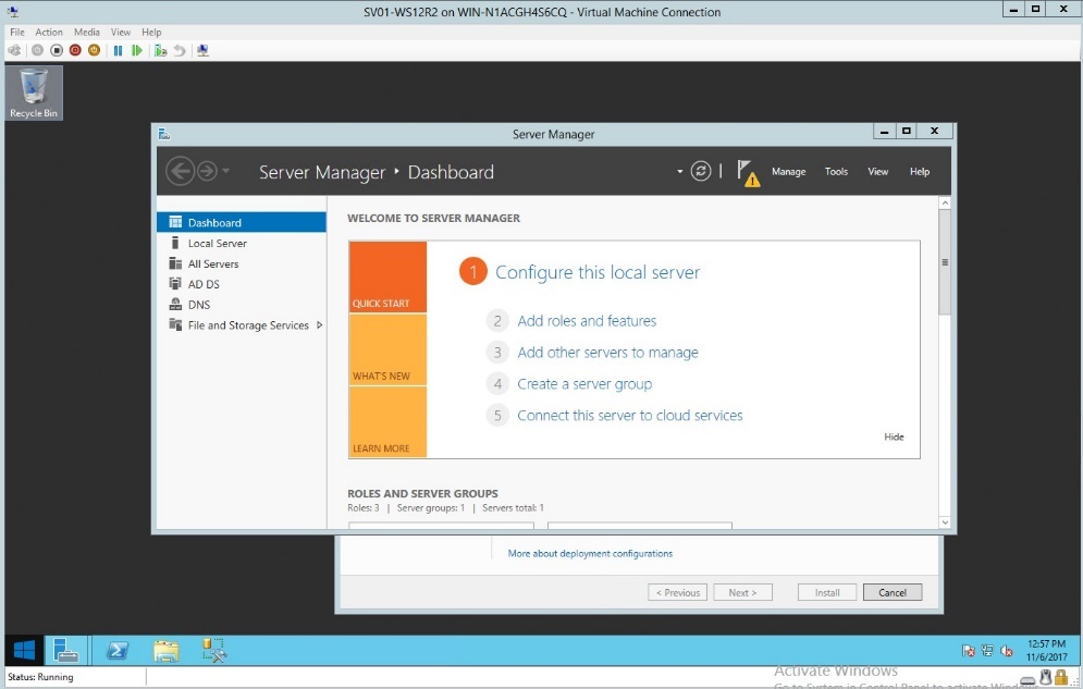
Figure 1.1 Dashboard of Server Manager
- In the deployment configuration select the “Add a domain controller”
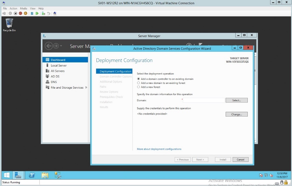
Figure 1.2 Deployment Configuration – Adding a domain
- In the deployment configuration select the “Add new Forest”
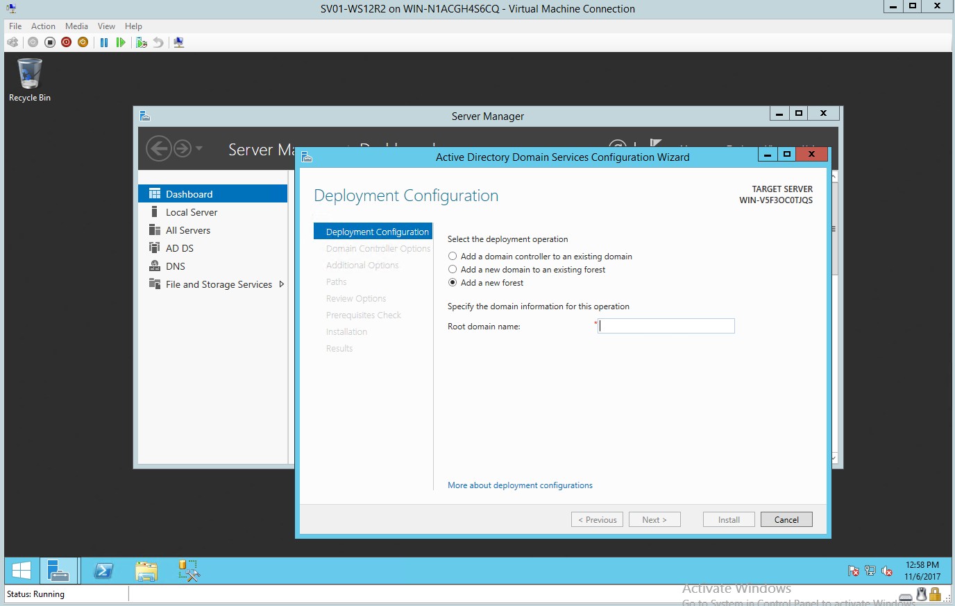
Figure 1.3 Deployment Configuration – Adding a new Forest
- In the Root domain name below the domain information type the desired root domain name.

Figure 1.4 Specifying the Root domain name
- In the domain controller option type the desired password and confirm your password.
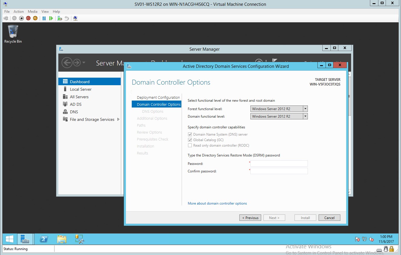
Figure 1.5 Domain Controller dialog box
- Additional option for adding the NetBIOS domain name
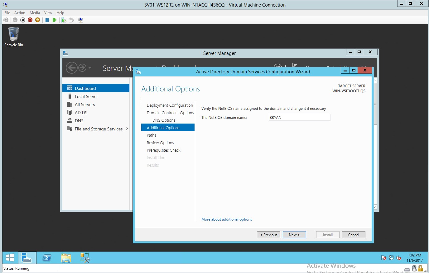
Figure 1.6 Adding NetBIOS domain name
- Selection of paths where to put the AD DS database log files
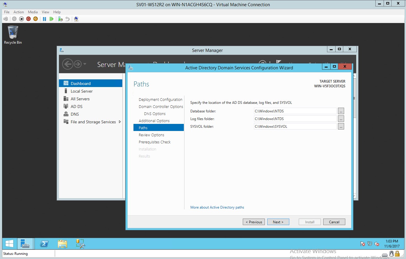
Figure 1.7 Location of the AD DS database log files
- Reviewing the options for the selected active directory domain services
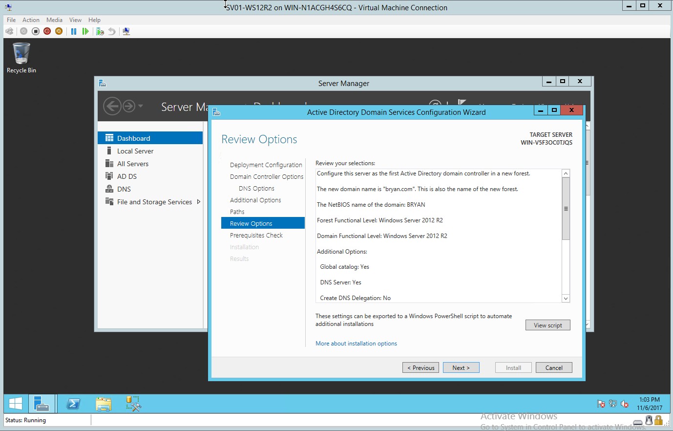
Figure 1.8 Review selection
- Checking the installation guide before installing all desired settings
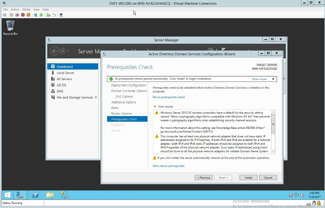
Figure 1.9 Prerequisites check
- Once installed, verify the username and password.
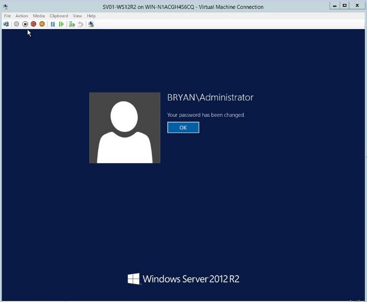
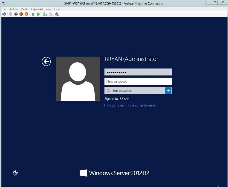
Figure 1.10 Windows Server Login page
- In the network and sharing centre, go to change adapter settings then go to properties.
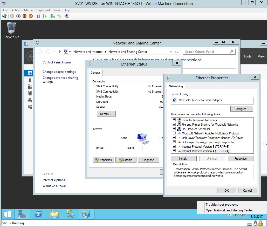
Figure 1.11 Ethernet properties
- Once the properties are clicked, enter the desired IP address, subnet mask and default gateway.
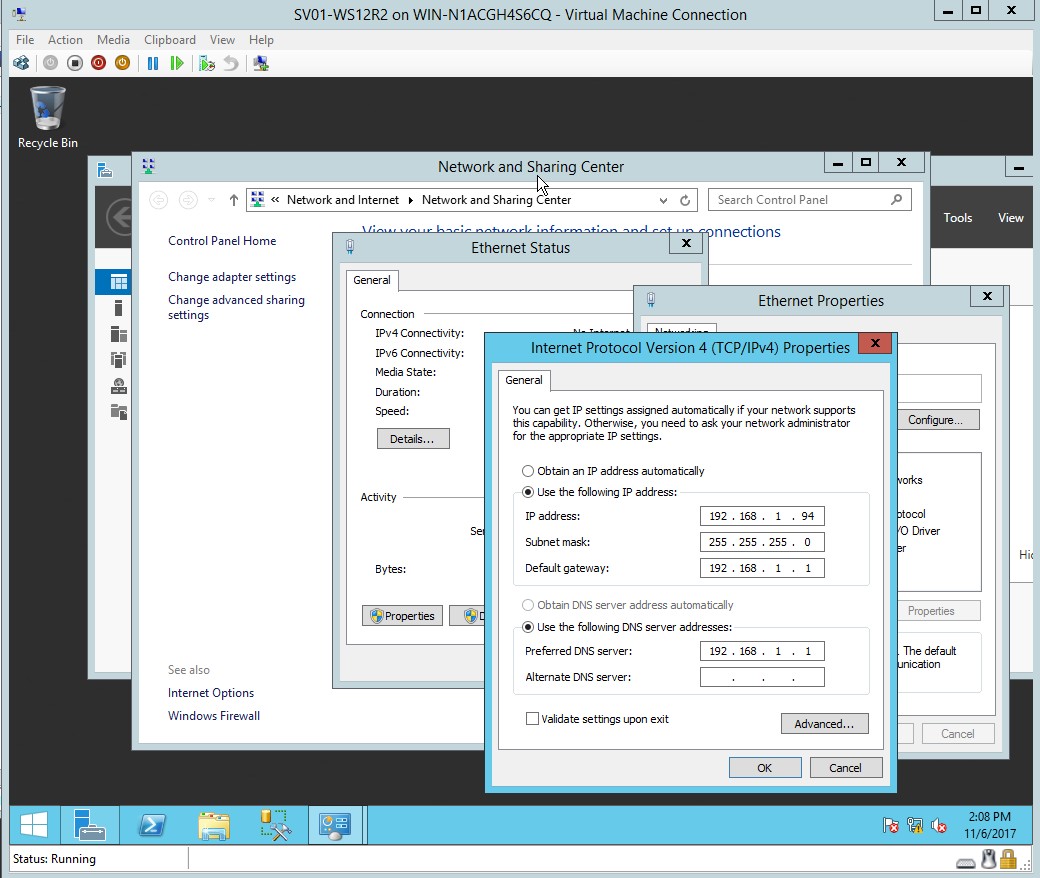
Figure 1.12 Internet protocol TCP and IPv4 properties
- Domain controller has been set together with the IP addresses.
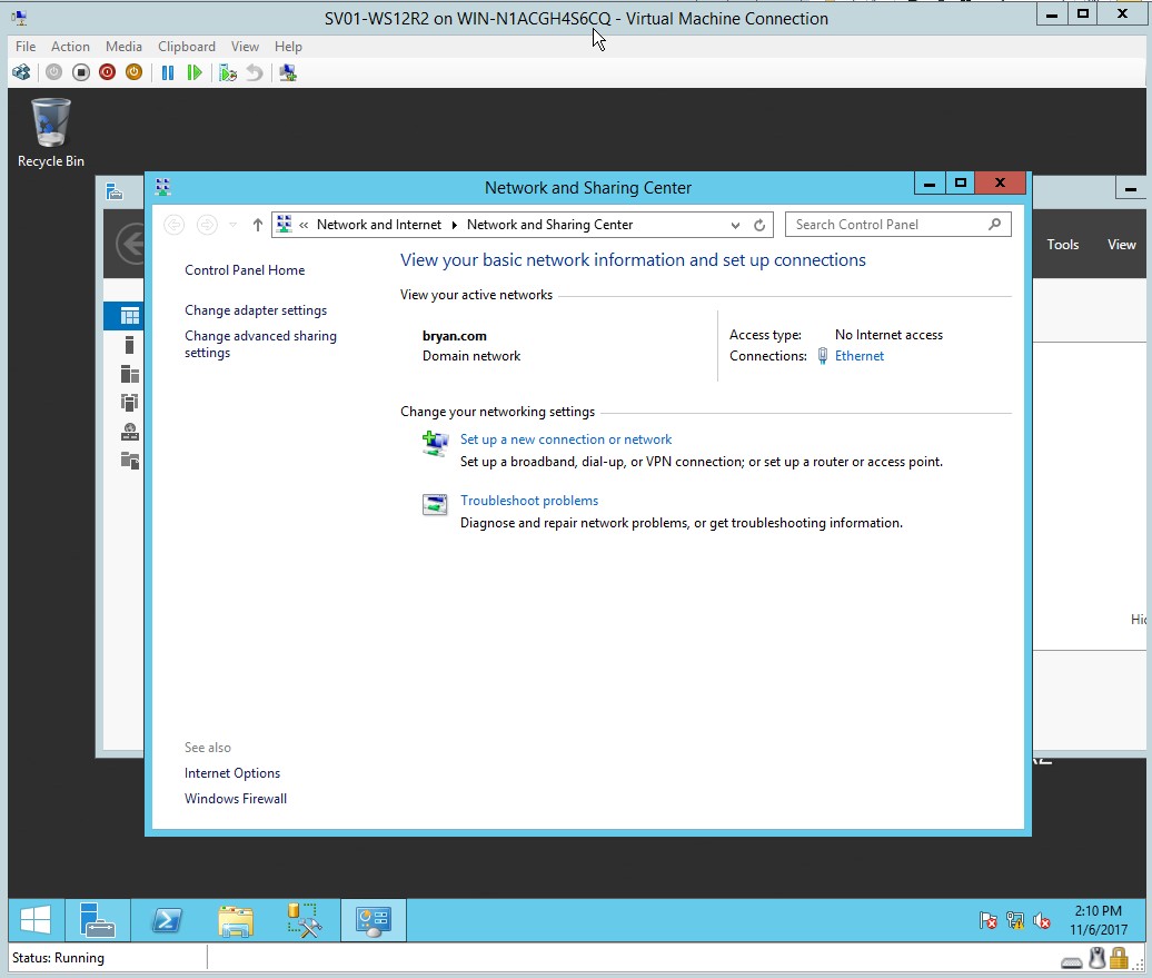
Figure 1.13 Network and Sharing Center
- Editing the Computer Name/Domain and joining in the domain
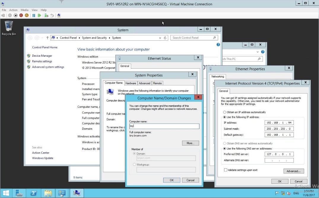
Figure 1.14 Domain name changes
- In the Server Manager, choose the Active Directory and Users
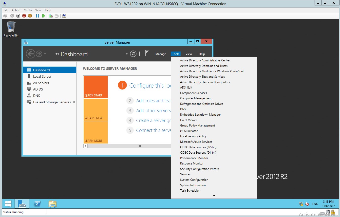
Figure 1.15 Server Manager GUI
- In the Active directory users and computers, you can find all the list information about the domain.
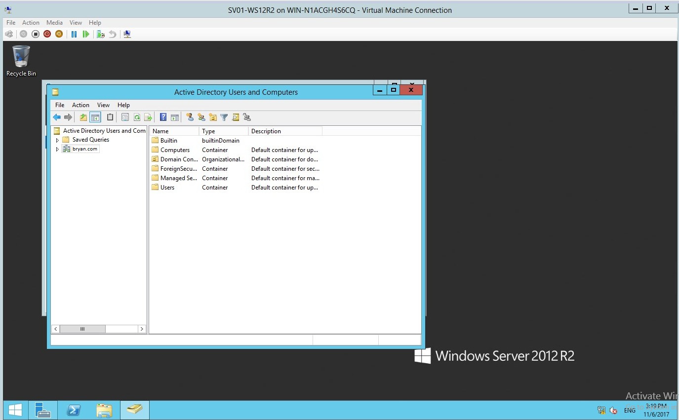
Figure 1.16 Active directory users and computers
- In the Active directory users and computers, add New Object then type the desired name.
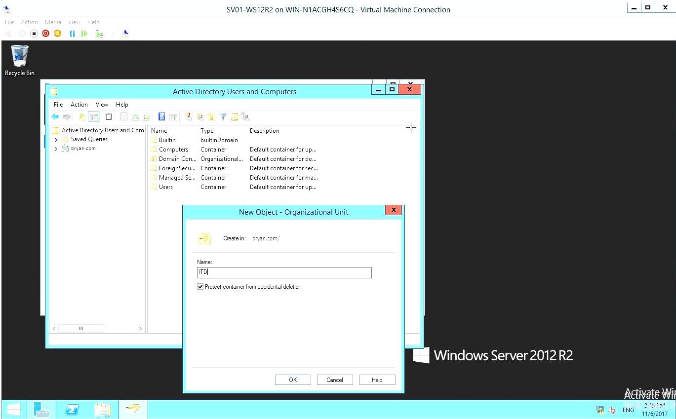
Figure 1.17 New Object Dialog box
- As you could see the ITD was added to the Active Directory Users
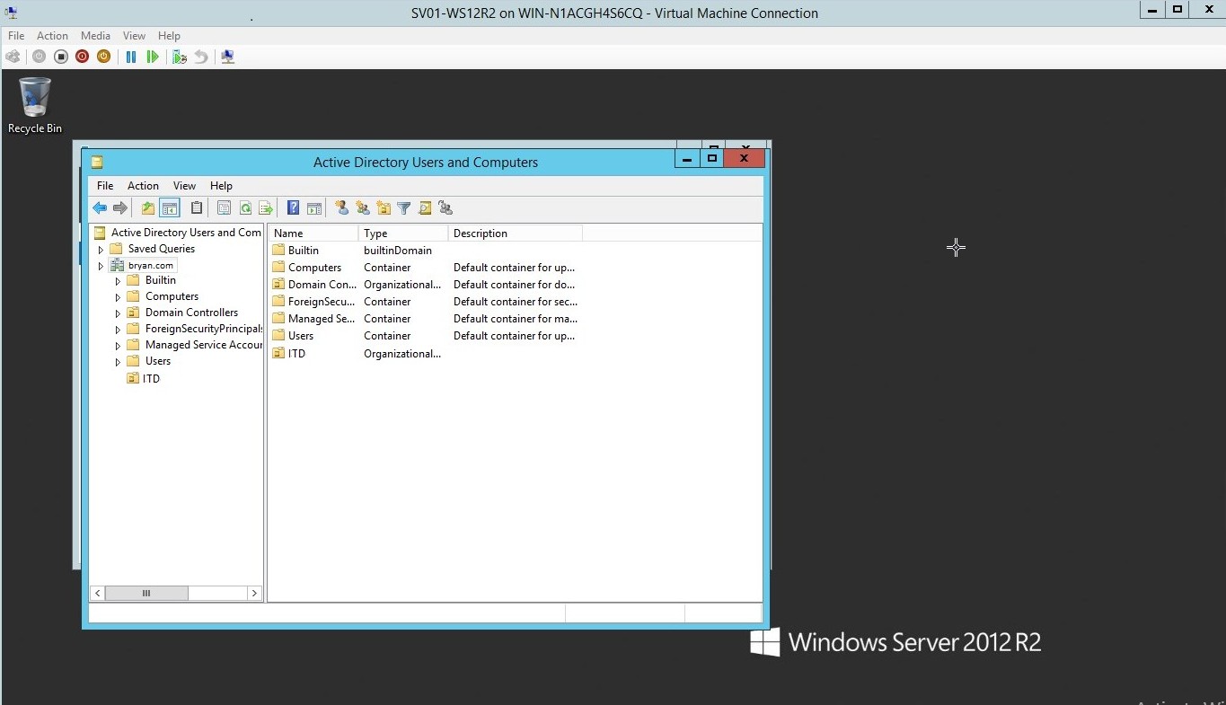
Figure 1.18
- Filling up the New Object to be created in the ITD domain
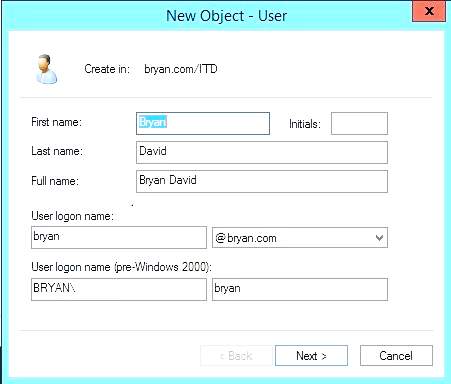
Figure 1.19a New Object fill-up dialog box
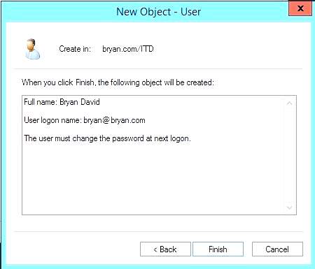
Figure 1.19b New Object was created successfully
- Creating the group name for the new object
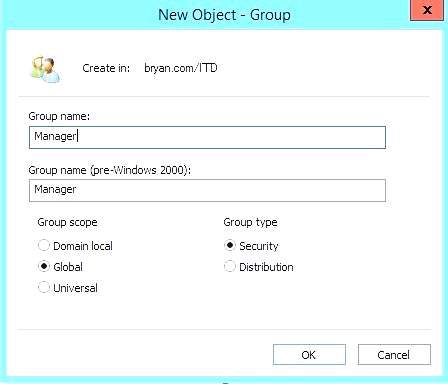
Figure 1.20 New Object – Group
- Manager was successfully added to the ITD domain
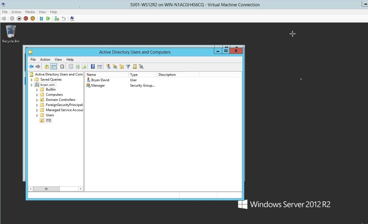
Figure 1.21 Active Directory – Bryan David and Manager
Print Server
- Download a copy of the HP printer installer from the official HP website.
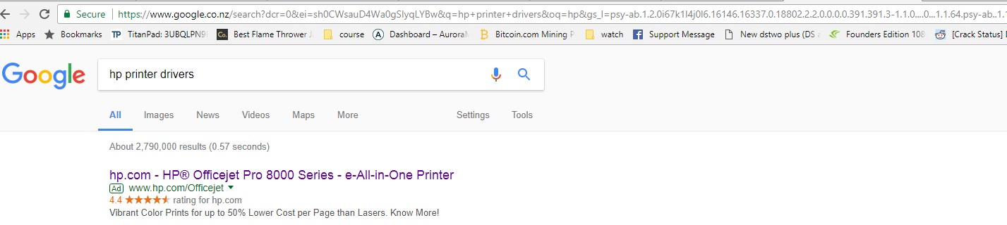
Figure 1.1.1 HP website
- From the HP website, download the installer of the selected printer.
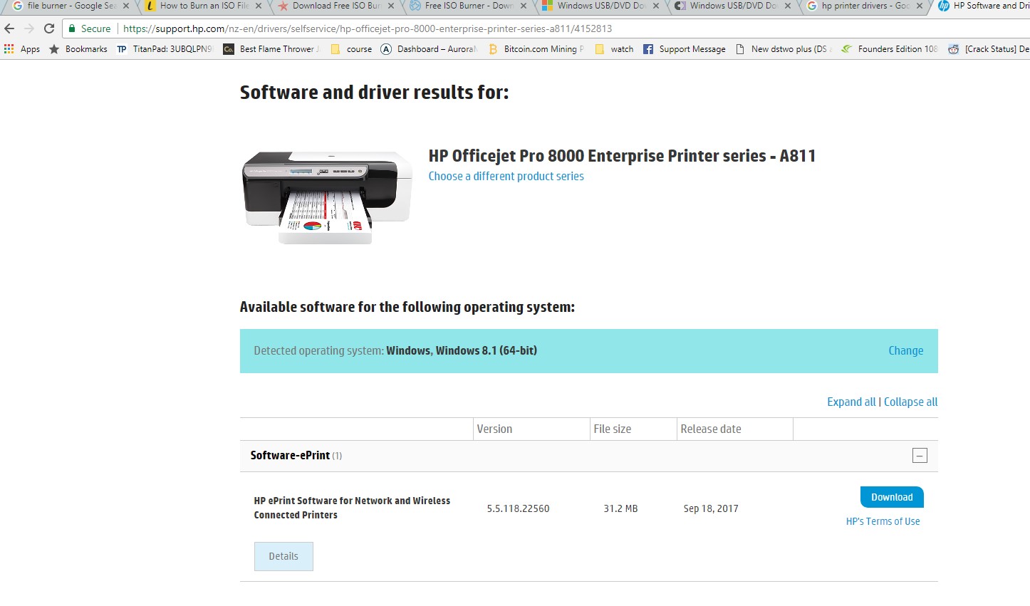
Figure 1.1.2HP installer
- This will be the .exe file of the HP printer installer
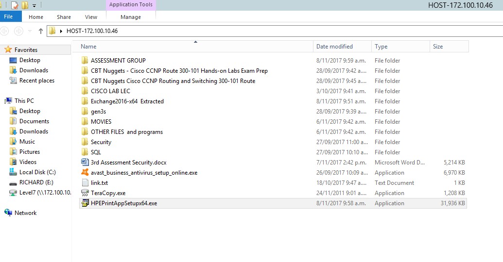
Figure 1.1.3 HPePrintAPPx64bit
- In the server manager, select the add role and features.
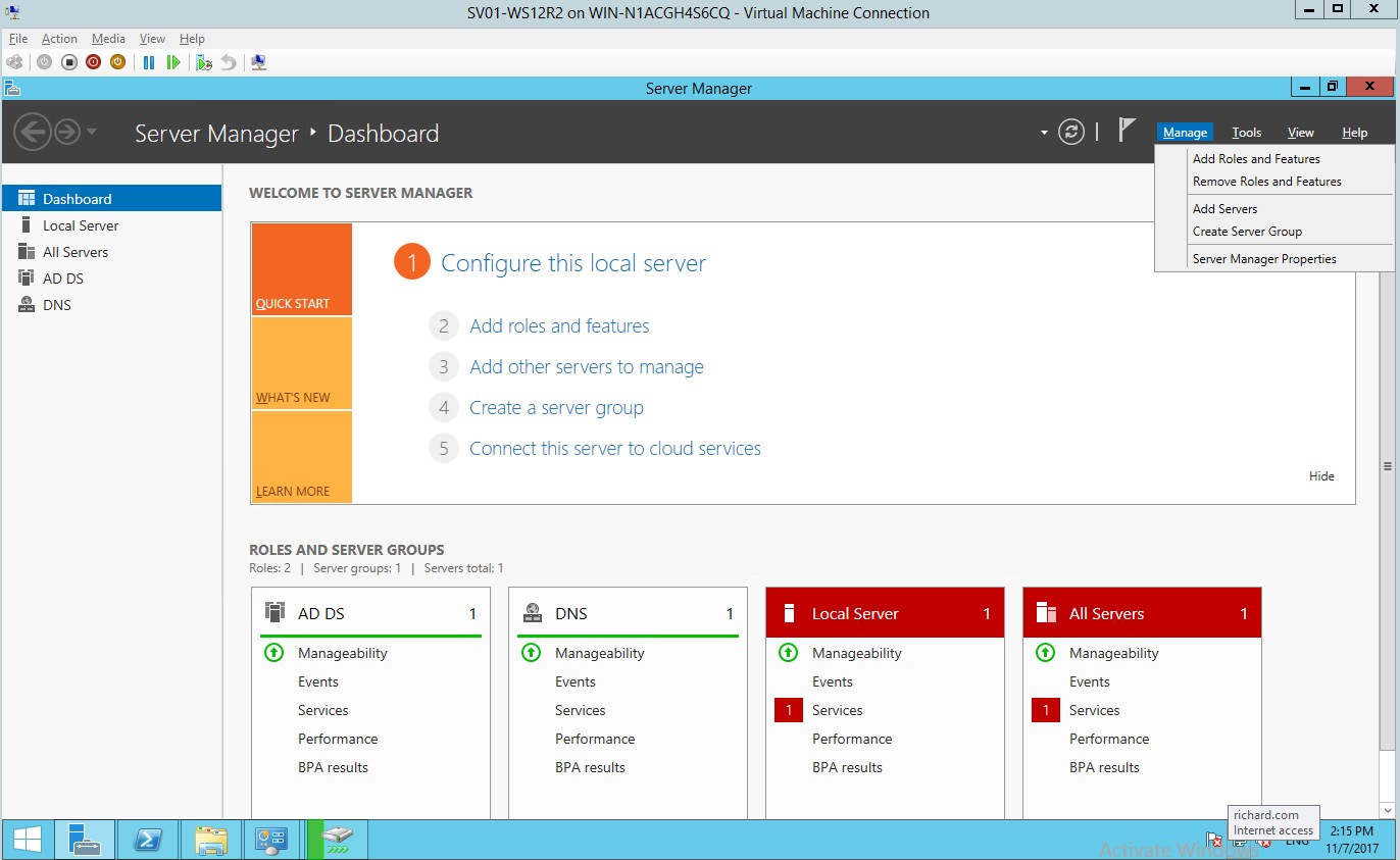
Figure 1.1.4Server Manager dashboard
- Adding roles and features wizard for the HP printer
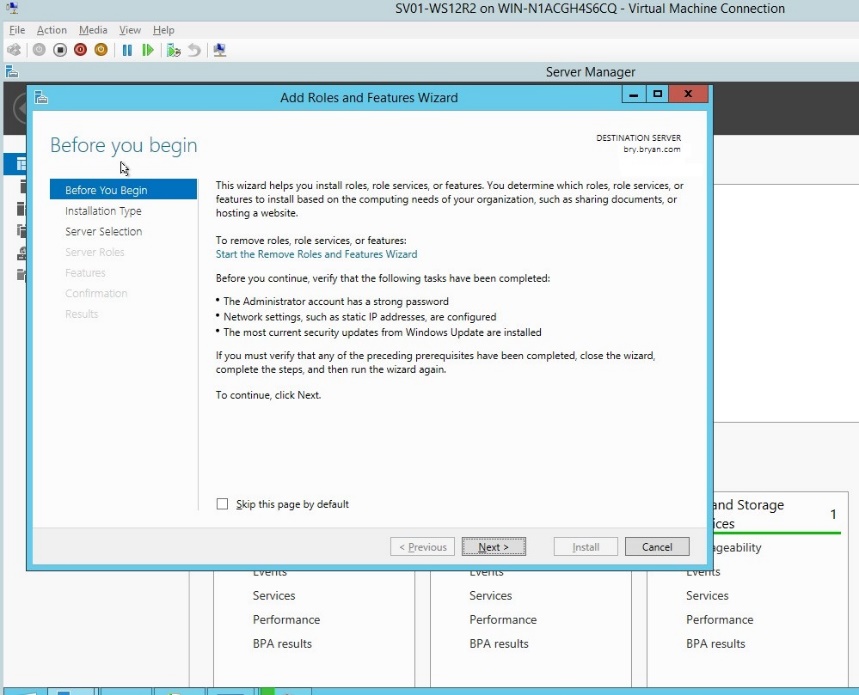
Figure 1.1.5Roles and features wizard
- Select the role-based or feature-based installation for the print server.
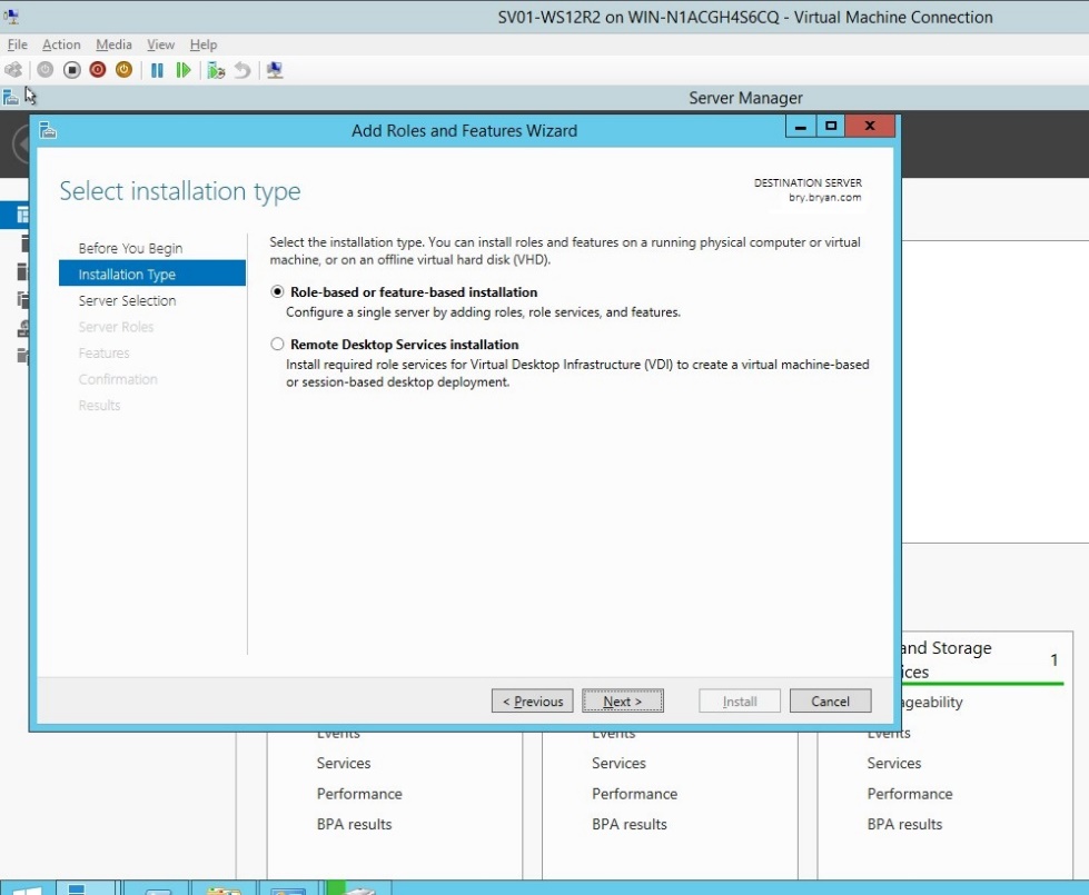
Figure 1.1.6Installation type for HP printer server
- In the server selection, select a server from the server pool.
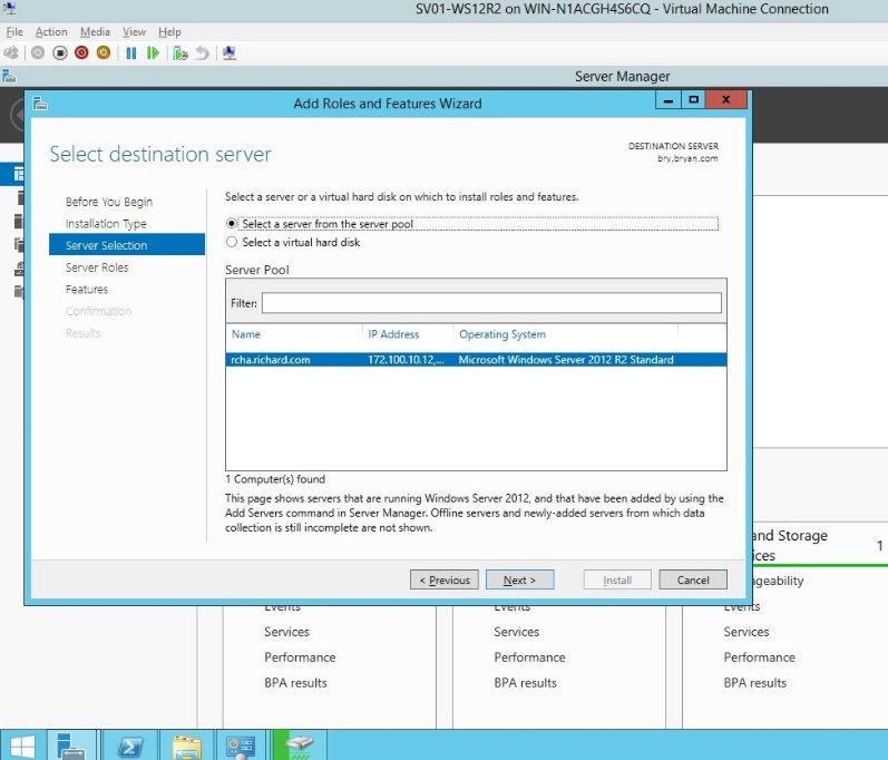
Figure 1.1.7 Server Selection
- Add the print and document services as the feature for the HP printer.
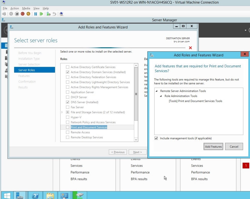
Figure 1.1.8 Add roles and feature wizard
- In the print and document services, click next.
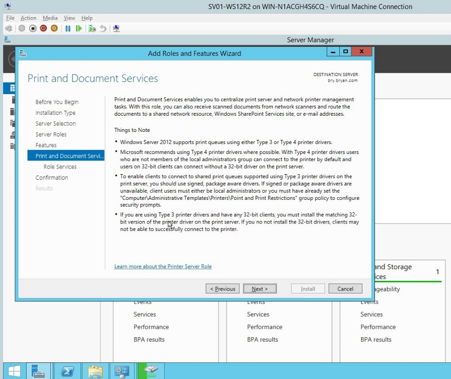
Figure 1.1.9 Print and document services
- Tick the Print server, scan server and internet printing for the role of HP print services.
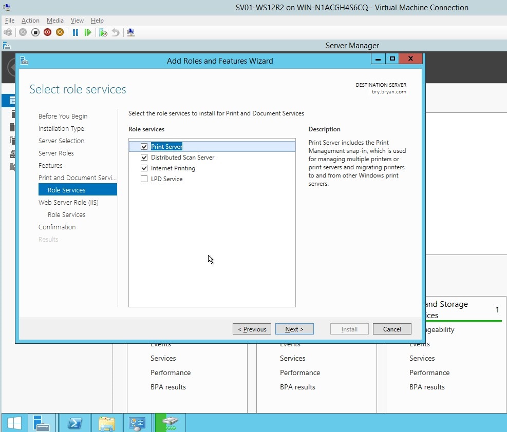
Figure 1.1.10 role services for the HP printer
- In the Web server role(IIS), click next.
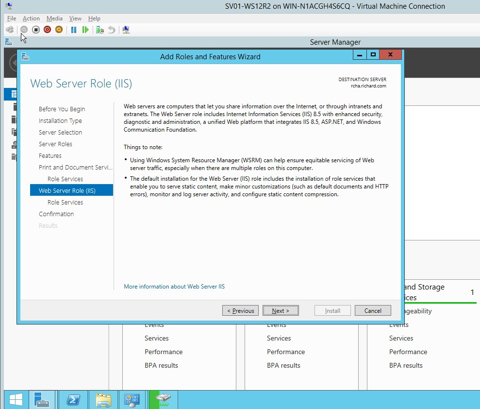
Figure 1.1.11 Web server role (IIS)
- Select all role services for the Print server desired.
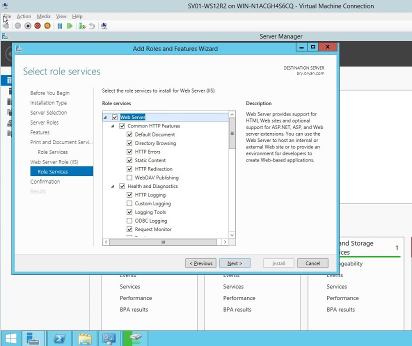
Figure 1.1.12 Web server for role service
- For the confirmation of the roles and features, review all selected and desired roles to be added.
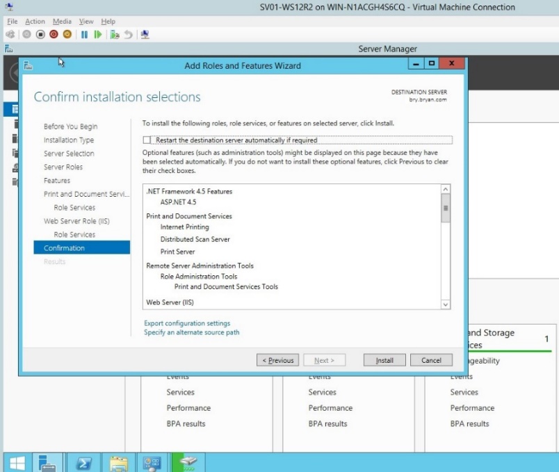
Figure 1.1.13 Confirmation of roles and features
- The result for the roles and features together with the installation of all roles added.
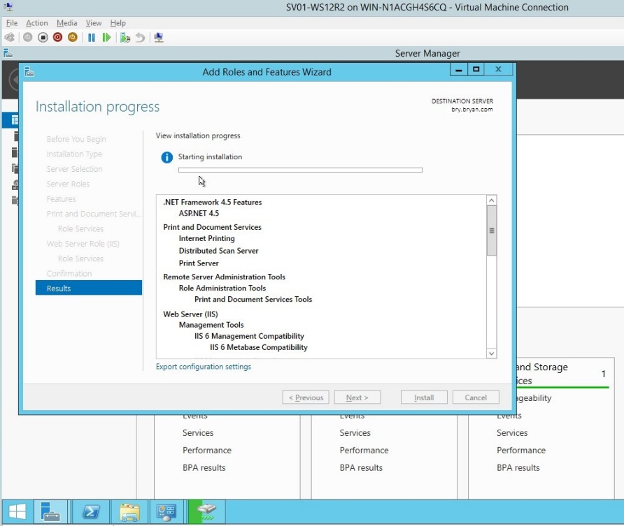
Figure 1.1.14 Result dialog box for the roles and features
- In the server manager, select the print management.
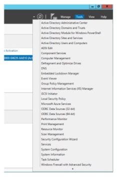
Figure 1.1.15Print management dropdown list
- In the print management, select filters, All printers.
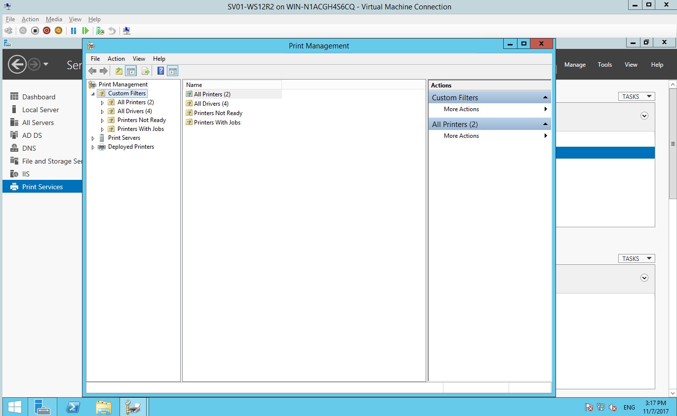
Figure 1.1.16 Print management
- In the all printers’ dropdown list, select the desired printer.
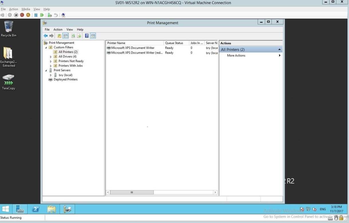
Figure 1.1.17 All printers
- Click the downloaded printer installer from the files downloaded.
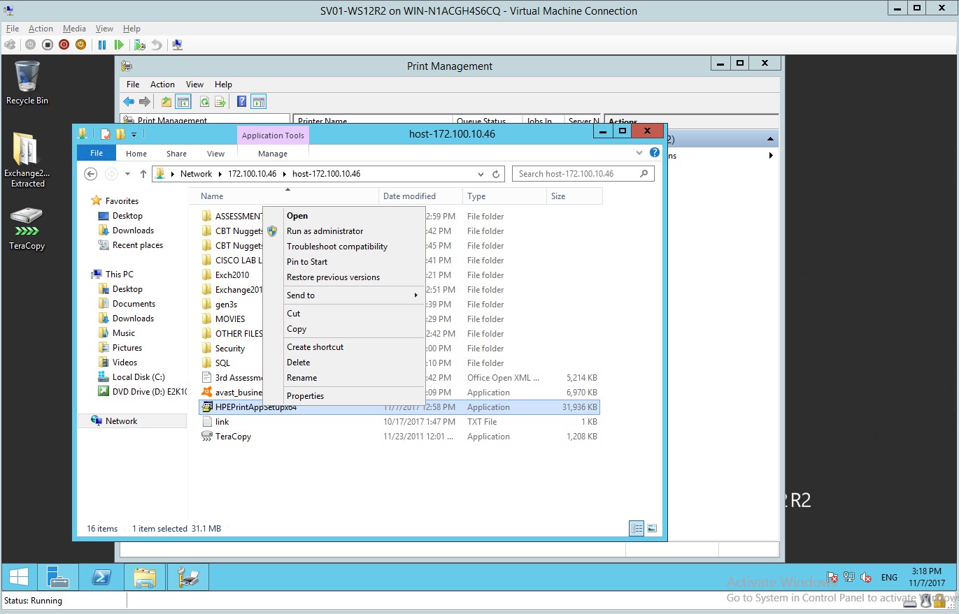
Figure 1.1.18 Printer installer
- The HP ePrint installer, click install.
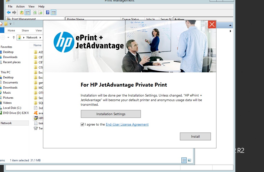
Figure 1.1.19installer for the HP printer
- The HP printer installer will install automatically.
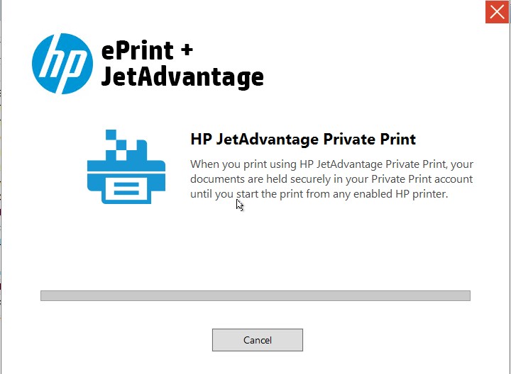
Figure 1.1.20 HP printer installer
- The HP printer installation is successful
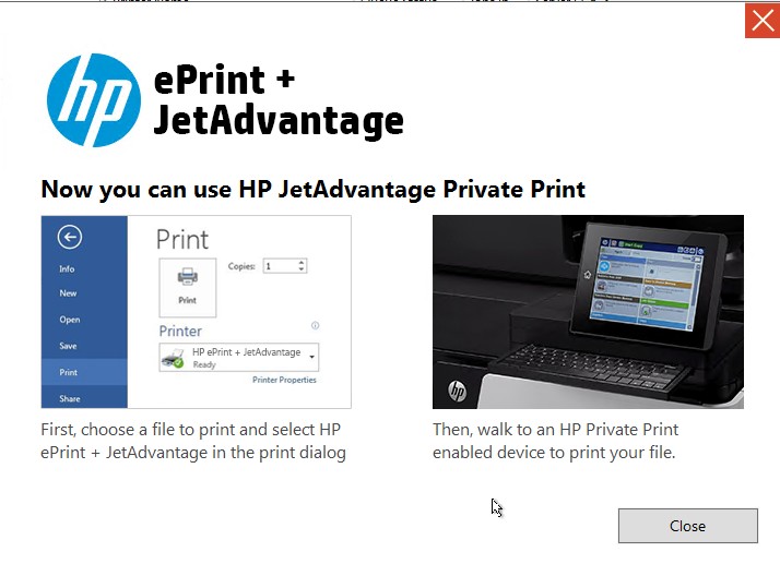
Figure 1.1.21 Printer installation
- Go back to the print management to select the desired printer.
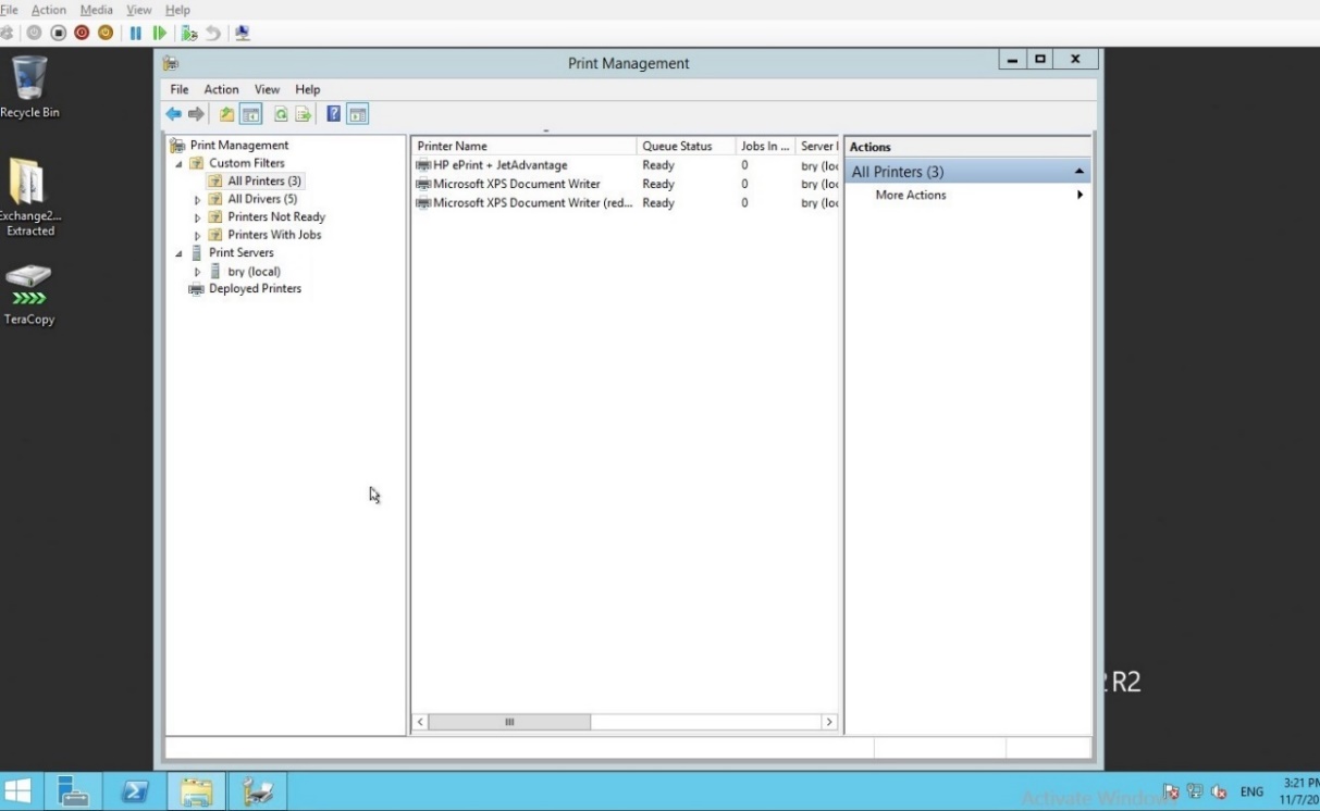
Figure 1.1.22Print management
- The HP printer will appear in the print management.
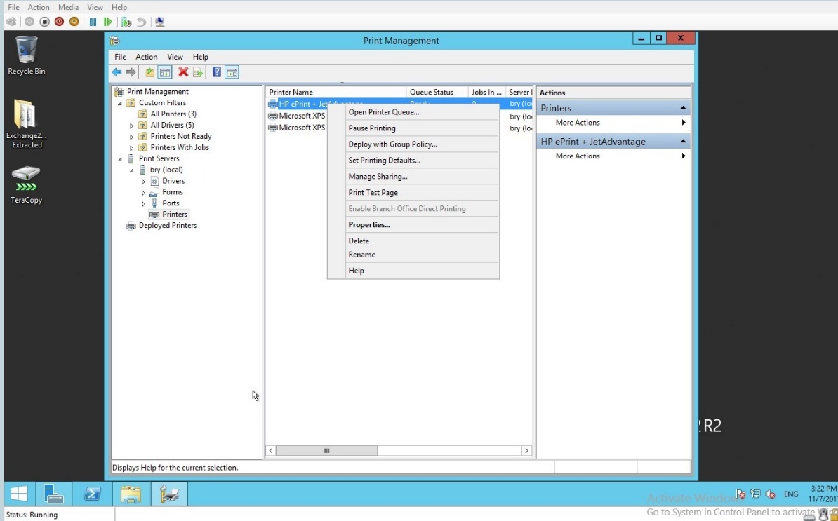
Figure 1.1.23 HP printer in the print management
- In the deploy with group policy, browse the group policy object name.
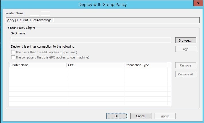
Figure 1.1.24 Deploy with GP
- In the browse for GPO, select the desired domain name.
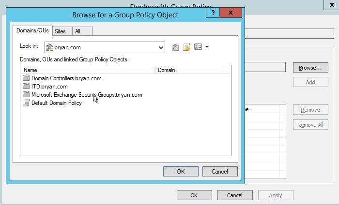
Figure 1.1.25 Browse GPO
- Select the Printer Group Policy with the domain ‘bryan.com’
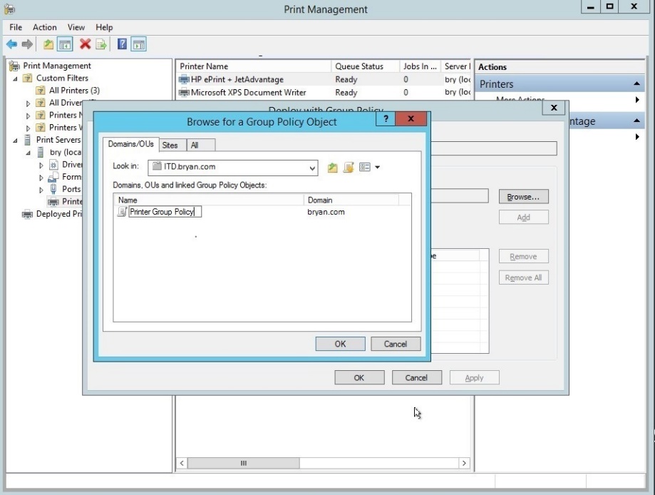
Figure 1.1.26 Browse GPO
- In the deploy with GP, add the bry GPO.
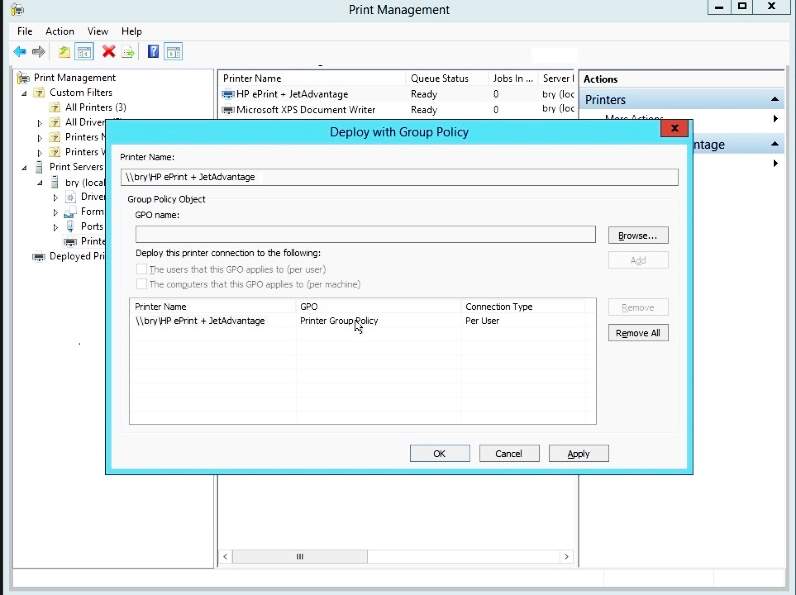
Figure 1.1.27 deploy with GP
- Printer deployment is successful
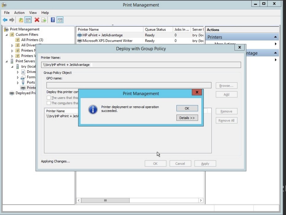
Figure 1.1.28 Print management dialog box
- Verification for the successful printer deployment
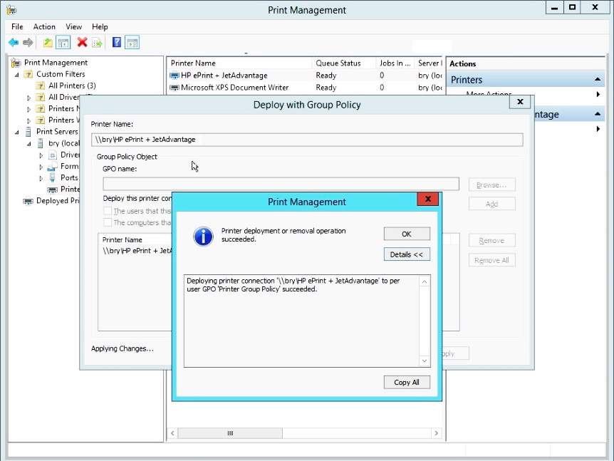
Figure 1.1.29 deployment successful dialog box
- HP eprint is successfully configured.
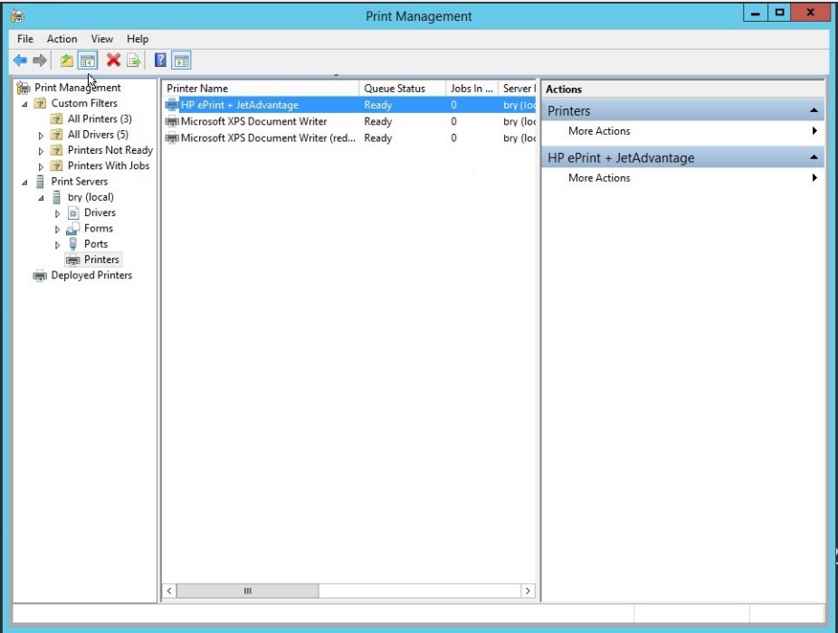
Figure 1.1.30 print management dialog box
- In the HP printer, right click then click the properties.
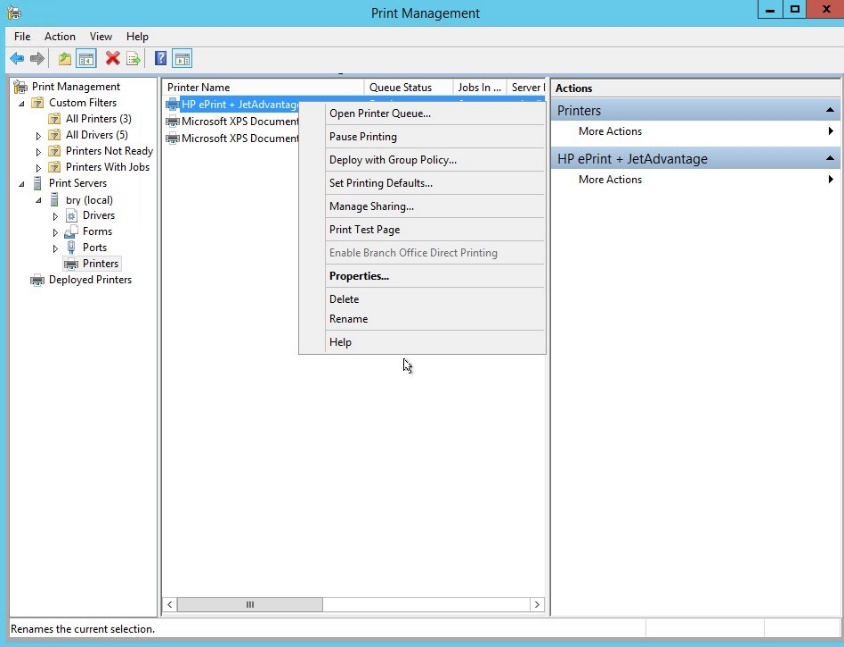
Figure 1.1.31 properties of the HP printer
- In the properties, select the security tab.
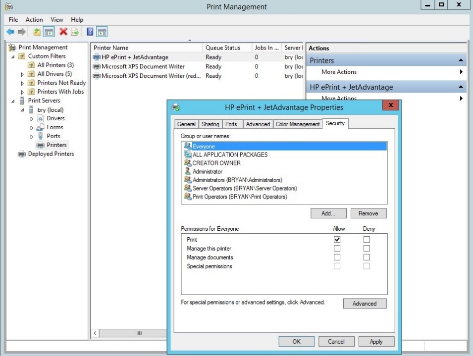
Figure 1.1.32 security tab for the HP printer properties
- In the security tab of the HP printer, select the administrator then tick the allow button for the print, manage the printer and manage documents.
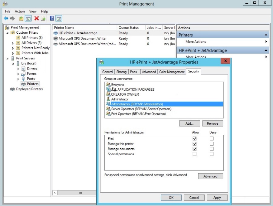
Figure 1.1.33 permission for administrator
Task 2 Exchange Server
Exchange server is a Microsoft product for messaging system that includes mail server, email client and groupware application. It is mainly design for companies for the employees to share information easily via taking advantage of Outlook server such that the company’s calendar and contact lists are always in sync. Minimum requirement for the exchange server is as follows: 64-Bit processor, 512GB RAM, 64GB disk space and an ethernet adapter. [2] Microsoft. (2017).
Setup Procedure:
- Install Windows Server.
- Insert the DVD installer for MS Exchange and use command prompt and enter the following commands:
d:, dir, cd exch…
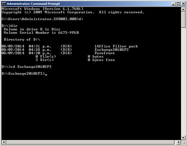
Figure 2.1 CMD installation of exchange server
- Inside the drive D (installer disk) type in the following commands:
setup /prepareschema
setup /prepareAD /OrganizationName:Avonmore
setup /PrepareAllDomains
- Open PowerShell and type in the command below:
Import-Module ServerManager
Add-WindowsFeature NET-Framework,RSAT-ADDS,Web-Server,Web-Basic-Auth,Web-Windows-Auth,Web-Metabase,Web-Net-Ext,Web-Lgcy-Mgmt-Console,WAS-Process-Model,RSAT-Web-Server,Web-ISAPI-Ext,Web-Digest-Auth,Web-Dyn-Compression,NET-HTTP-Activation,Web-Asp-Net,Web-Client-Auth,Web-Dir-Browsing,Web-Http-Errors,Web-Http-Logging,Web-Http-Redirect,Web-Http-Tracing,Web-ISAPI-Filter,Web-Request-Monitor,Web-Static-Content,Web-WMI,RPC-Over-HTTP-Proxy –Restart
Set-Service NetTcpPortSharing –StartupType Automatic
- Install the office filter pack found inside the cd installer.
- Install exchange server 2010
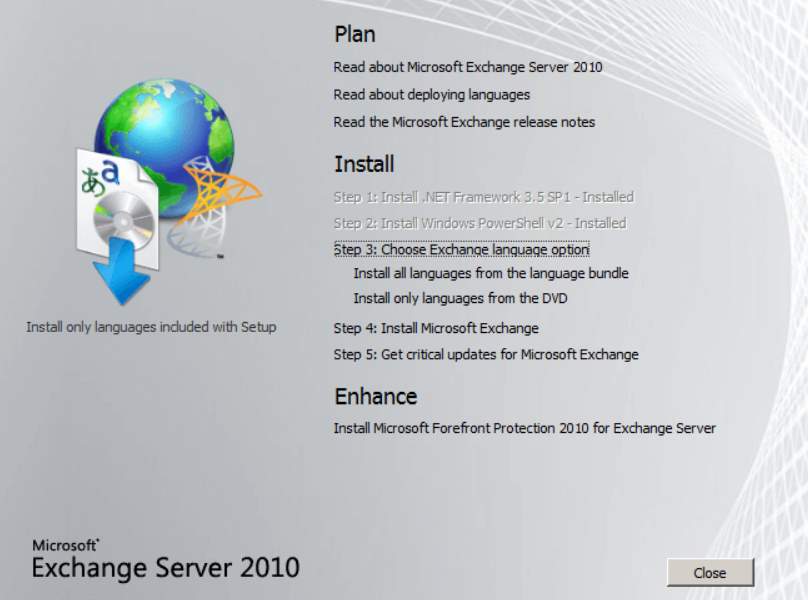
Figure 2.2 Installation of exchange server
- In the Exchange server 2010 setup, click next.
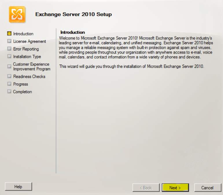
Figure 2.3 Introduction
- In the installation type, select the typical exchange server installation.
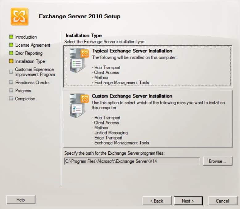
Figure 2.4 Installation type
- In the exchange organization, type your desired name.
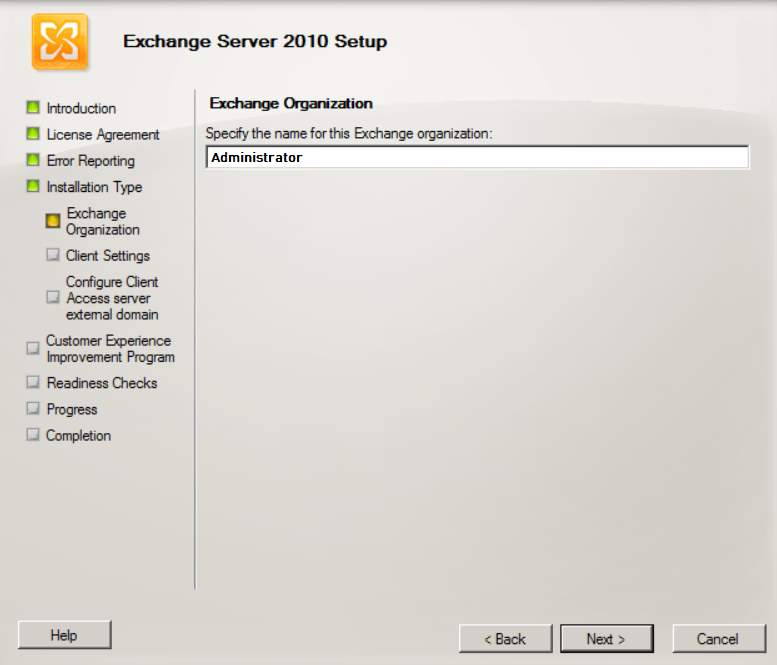
Figure 2.5 Exchange Organization
- In the client setting select’No’.
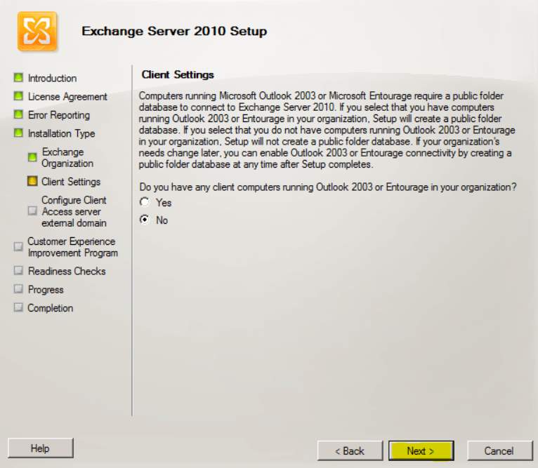
Figure 2.6 Client Setting
- Type your desired name for your client access.
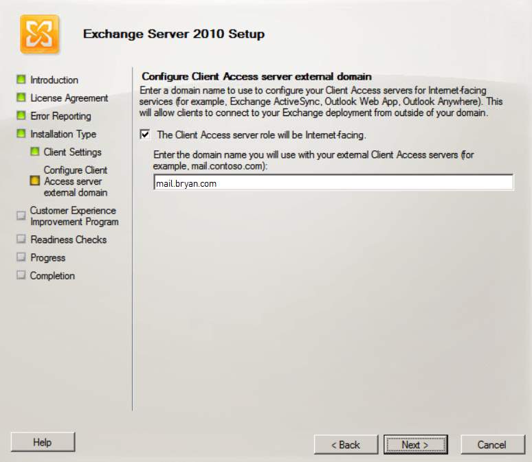
Figure 2.7 Configure Client Access Server external domain
- Select the “I don’t wish to join the program at this time”
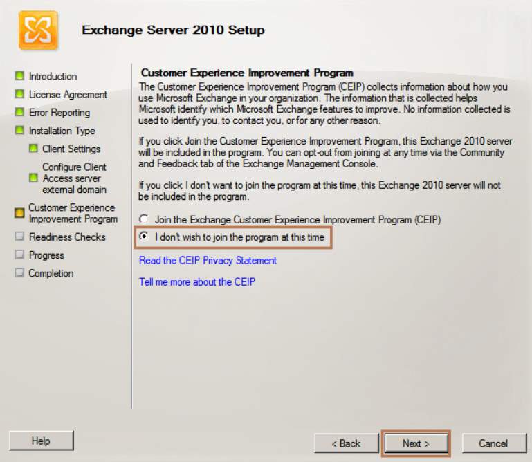
Figure 2.8 Customer Experience Improvement Program
- In the readiness checks, review all the selected mode before installation.
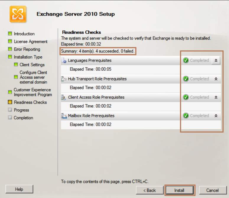
Figure 2.9 Readiness Checks
- Upon completion, click finish.
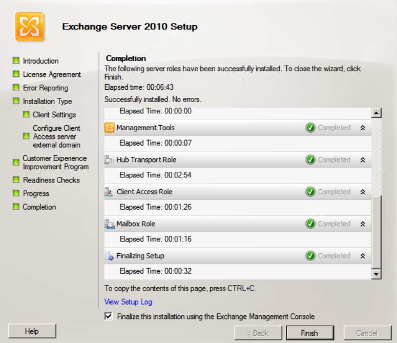
Figure 2.10 Completion
Configuring Mailbox Roles
In this setup, we are going to configure the Exchange server to perform multiple in order for our users to send and receive emails. We need to include the following: (1) Hub transport – responsible for routing messages (2) Client Access – offers all available protocol access to mailboxes (3) Mailbox – this contains the mailboxes and public folders. We need these three roles for the Exchange Management Console to make the necessary changes.
- Open Exchange Management Console and choose Organization Configuration on the left pane. Select your server and click New Mailbox Database on the right.
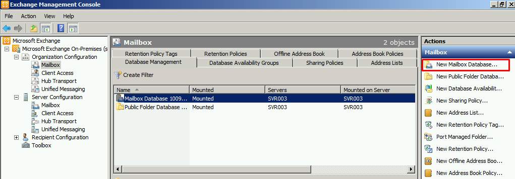
Figure 2.11 Exchange Management Console
- Follow the onscreen instruction on setting the location for the database and click on Finish once done.
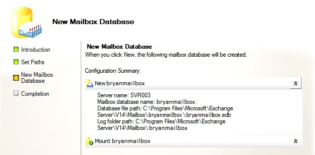
Figure 2.12 New Mailbox Database
Sending and receiving emails via web browser:
- To access the web mail, we simply go type in the URL of the server and add /owa on the address.
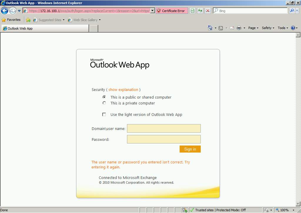
Figure 2.13 Outlook Web App
- Upon successful login the user will be presented by an Outlook Web App and he can then start sending and receiving emails.
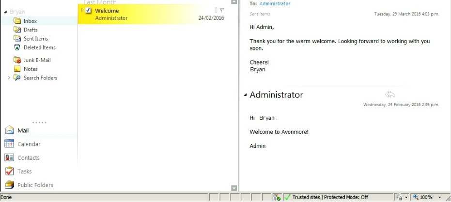
Figure 2.14 Email Test
Task 3 Barracuda Spam Filter
Barracuda Spam Filter is an integrated software and hardware solution to protect the email server from virus, spam, spoofing and spyware attacks. [3] Barracuda. (2017).
These are the steps for the users on how to setup:
- Login to Barracuda Spam Filter as administrator and add the IP configuration, DNS, and domain name of the email server admincore.com
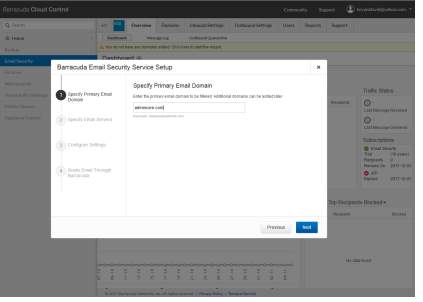
Figure 3.1 Basic Set up for Email Security
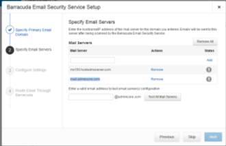
Figure 3.2 Email server Setup
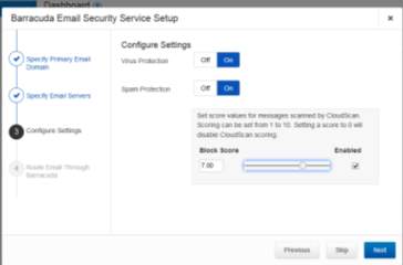
Figure 3.3 Virus and Spam protection
- Setup the quarantine procedure for emails that contain spam and viruses.
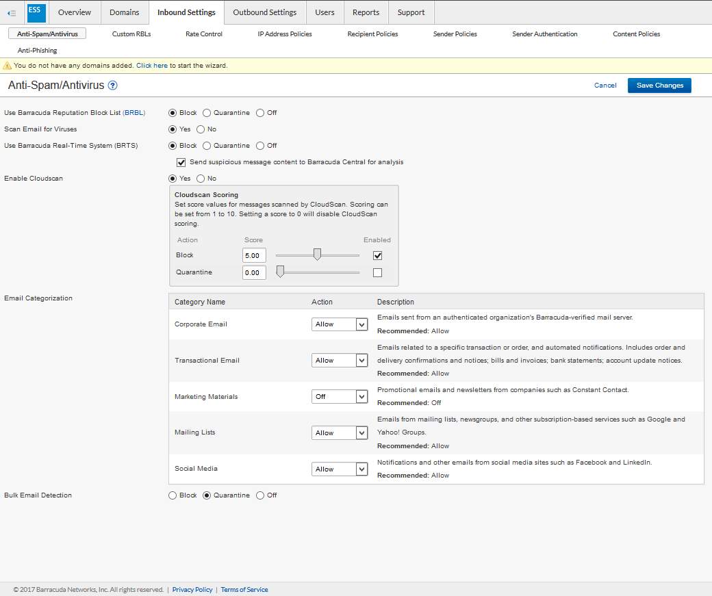
Figure 3.4 All inbound setting for email protection
- Updates allows the spam filter system to determine incomming spam threats
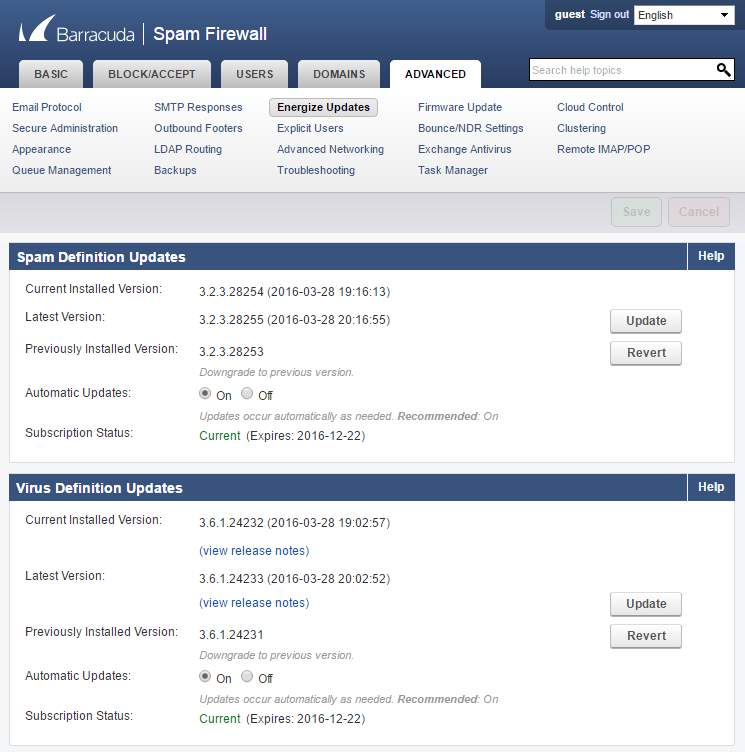
Figure 3.5 Updates for barracuda Part 1
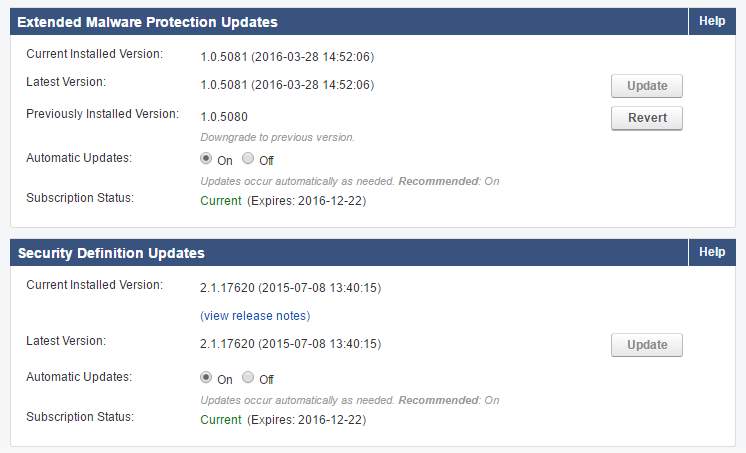
Figure 3.6 Updates for barracuda Part 2
- The Domain tab will allow to add allow or block domain.
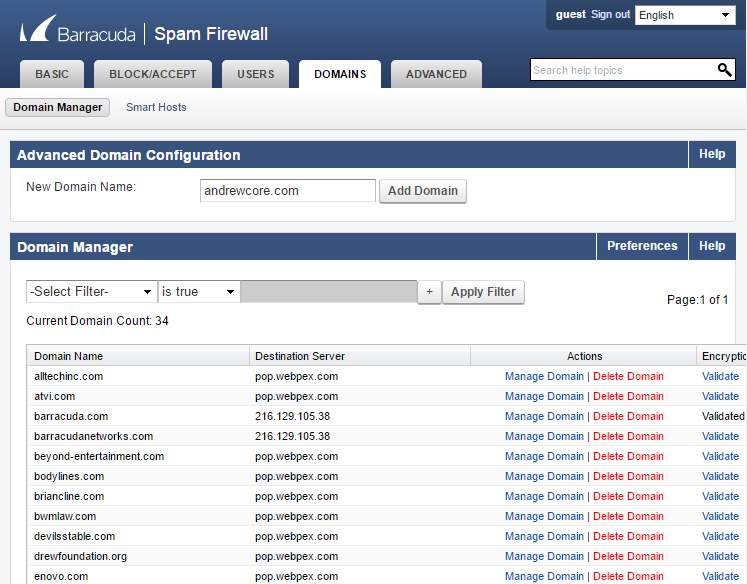
Figure 3.7 Domain manager
- Spam Scoring Limit will limit the block, quarantined and tag mails.
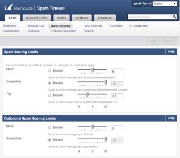
Figure 3.8 Inbound and outbound Spam scoring limits
- The Rate Control will allow the administrators to set connections per IP address allowed.
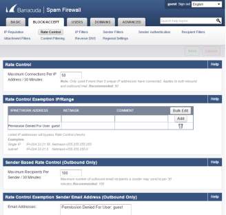
Figure 3.9 Rate Control
- Sender Filters will filter all mails incoming to the mail server.
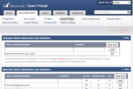
Figure 3.10 Incoming email filters
Task 4 Microsoft Office Outlook
Microsoft Office Outlook is an information manager for Microsoft. It includes email application, calendar, contacts list, notepad, journal and also web browsing. It can be used with exchange server, SharePoint server or a stand-alone program. It is commonly used as the email server for all companies worldwide as it is easy to use and has a lot of function. [4] Rouse. (2012).
Steps on how to manage MS Outlook:
- In the start button of the windows server select the Microsoft Outlook 2010.
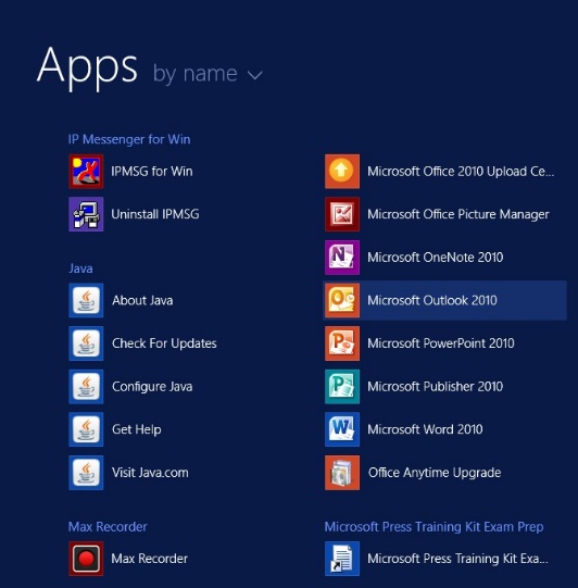
Figure 4.1 Microsoft Outlook 2010
- In the control panel, look for the Mail setup – Outlook
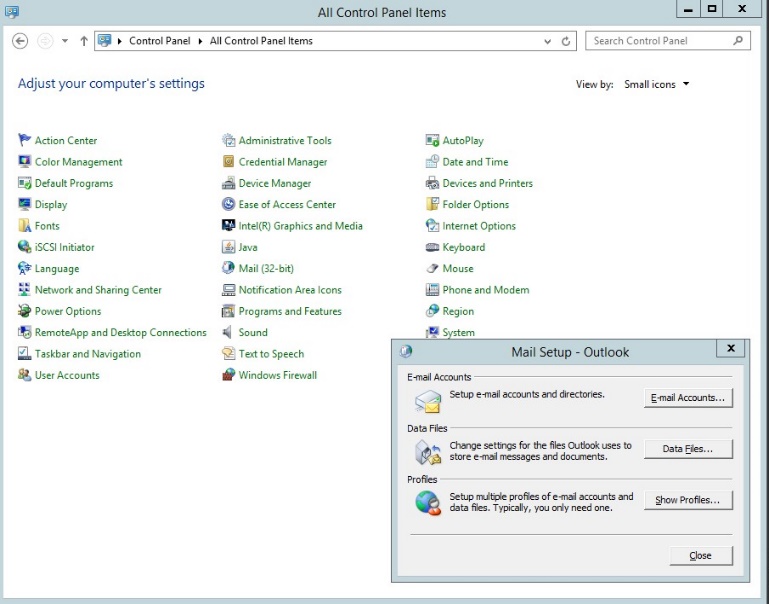
Figure 4.2 Mail Setup – Outlook
- Selectin the account settings for the email
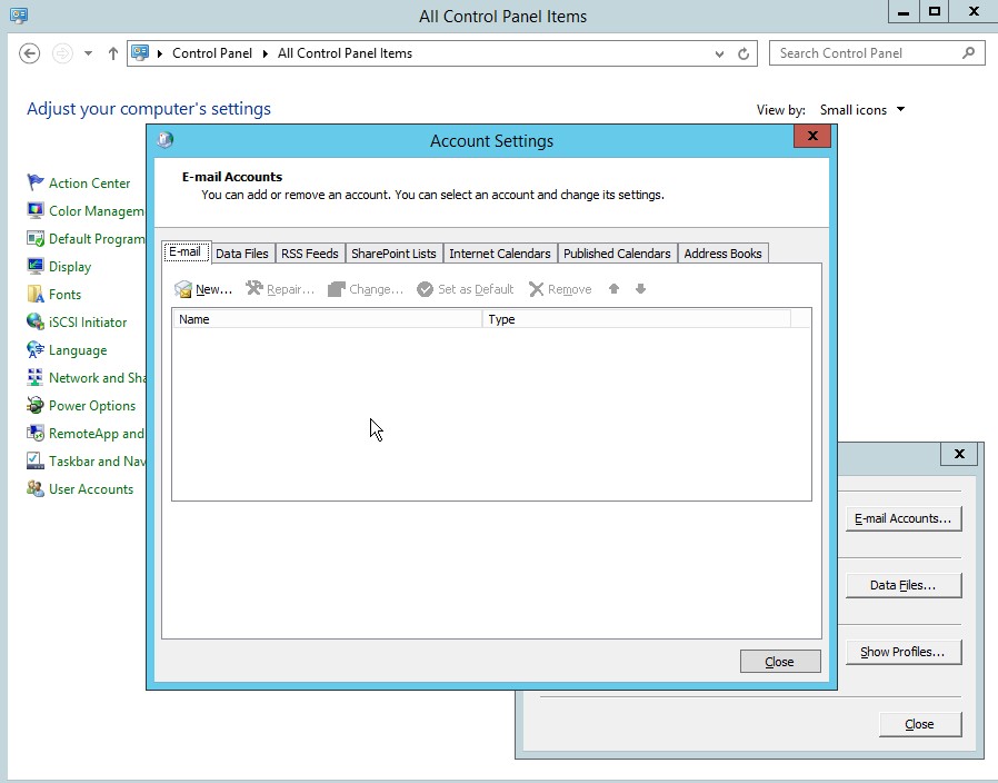
Figure 4.3 Account settings for Outlook
- Then add new account, select manually configure server settings.
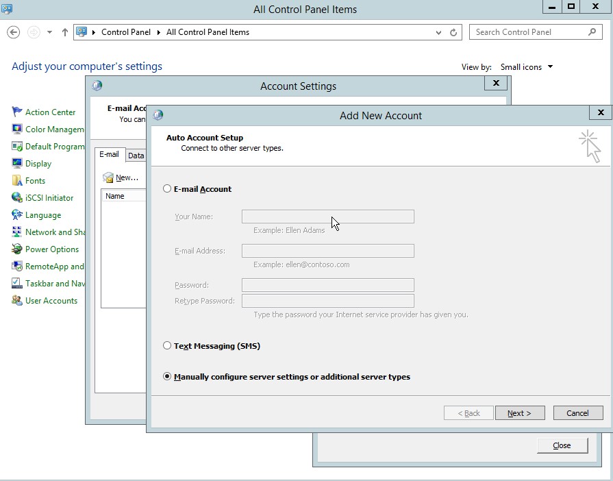
Figure 4.4 Add new Account dialog box
- Select the Internet E-mail in the add new account settings.
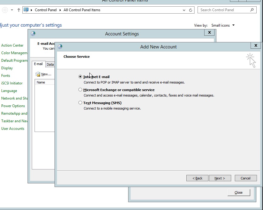
Figure 4.5 Add new Account dialog box
- Type the desired user information, server information and logon information, the click next.
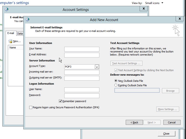
Figure 4.6 User, server and logon information for the New account
- Type this URL ‘https://help.yahoo.com/kb/SLN4724.html”This information is important to setup the email for the outlook
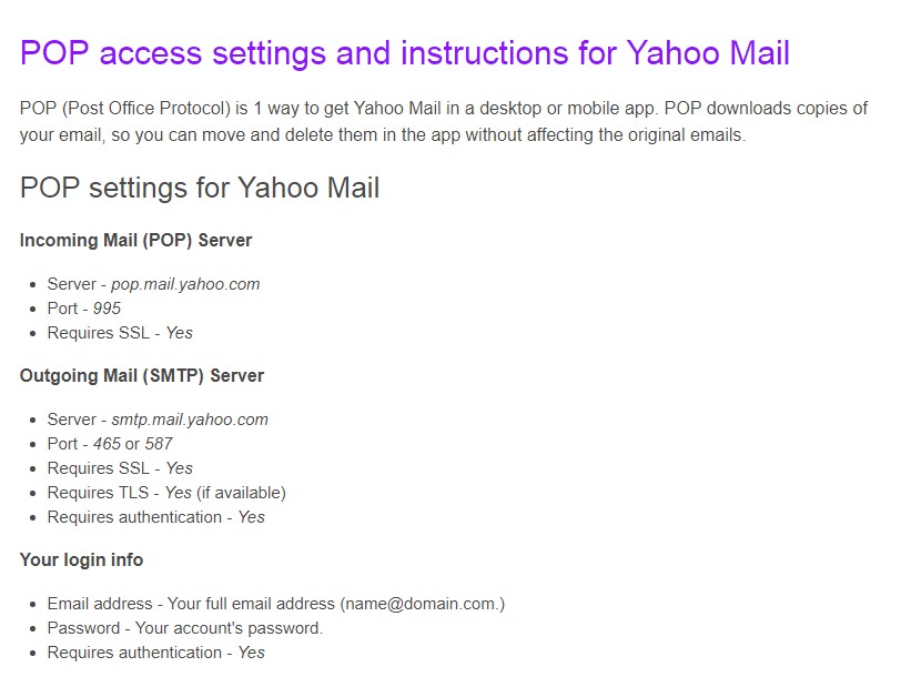
Figure 4.7 Yahoo mail POP setting
- After setting up the new account. Click next.
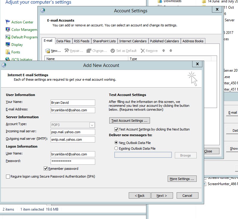
Figure 4.8 Add new account information
- Type your desired email address in the internet E-mail settings
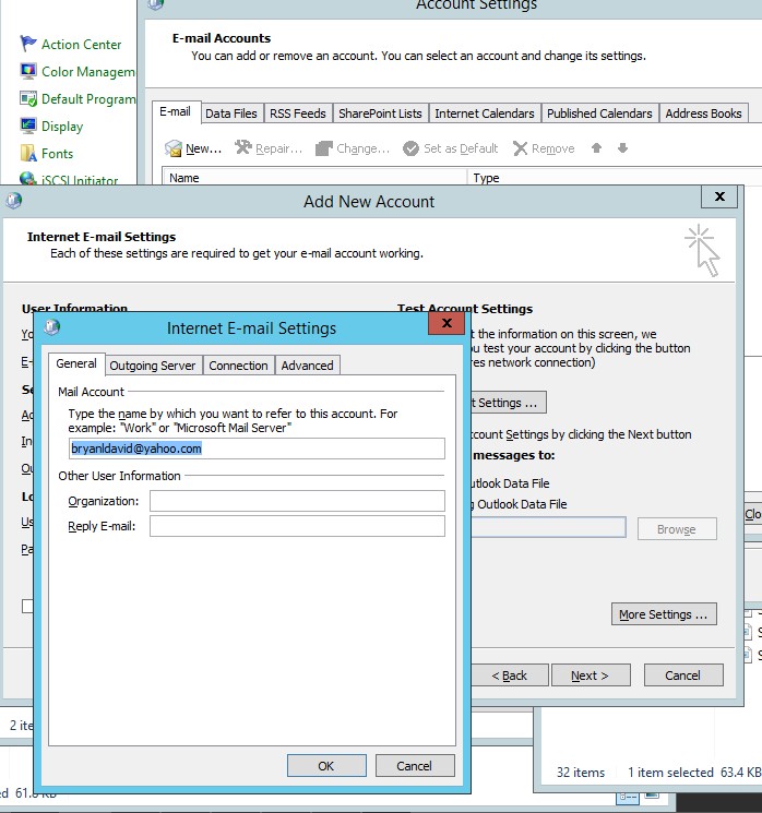
Figure 4.9 internet E-mail settings
- In the outgoing server, select the “same settings as my incoming mail server”.
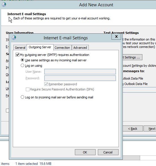
Figure 4.10 Internet e-mail setting for the outgoing server
- Go to the advanced setting then copy the information from the POP yahoo mail setting.
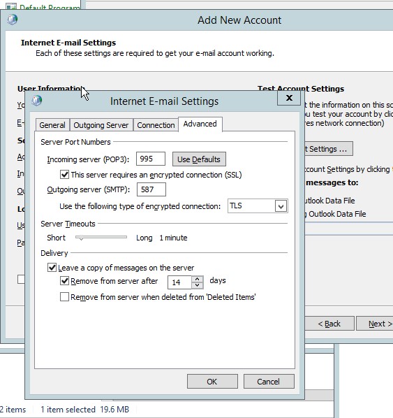
Figure 4.11 Advanced setting for the e-mail
- Be sure to test the account settings to verify the email services.
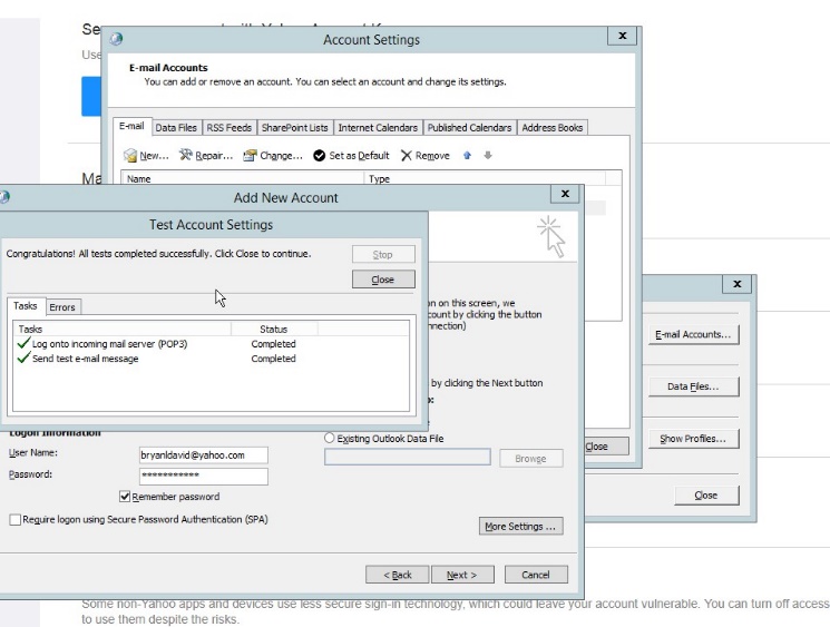
Figure 4.12 test account settings
- As you could see all the emails are in the e-mail list accounts.
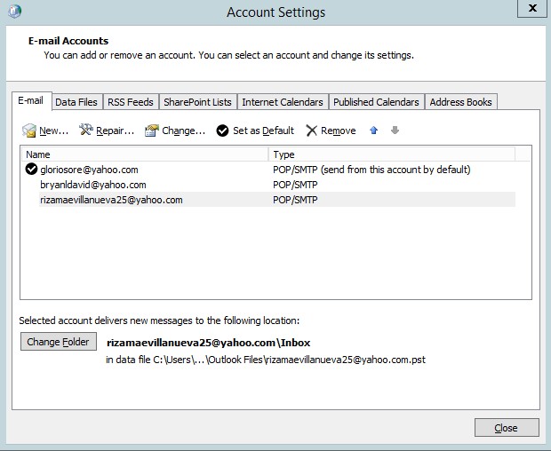
Figure 4.13 email settings
- In the data files, we could see the location of the email.
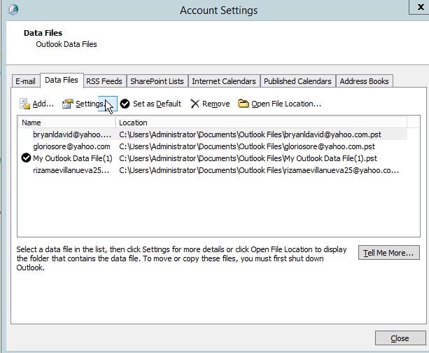
Figure 4.14 data files of the email
- Official dashboard for the outlook which contains all email in one program.
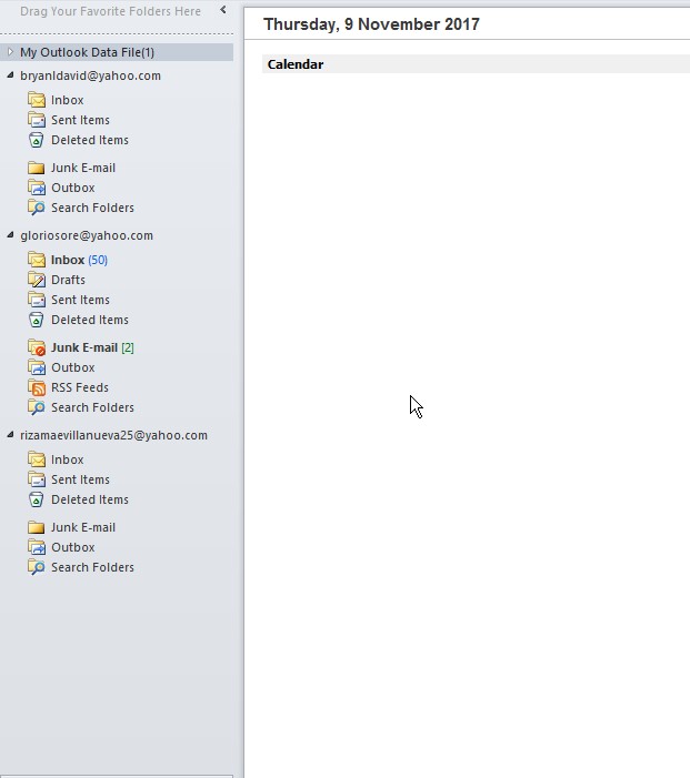
Figure 4.15 Microsoft Outlook
- Click in the New email to test the email server/
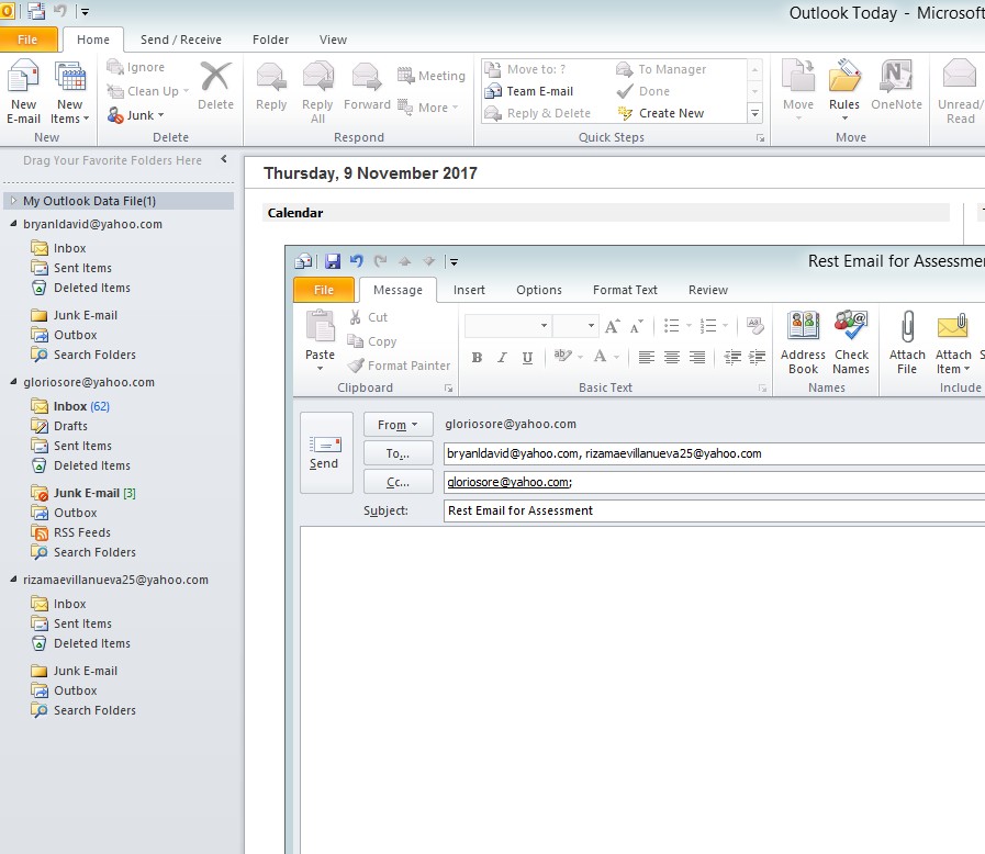
Figure 4.16 pop up window for the email
- Email setup for the bryanldavid@yahoo.com which includes all information.
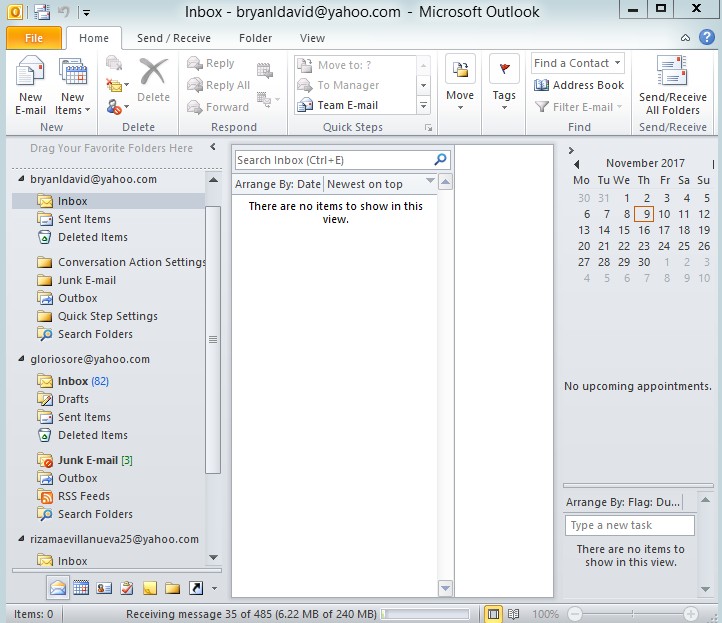
Figure 4.17 Microsoft outlook
- Testing client to client email
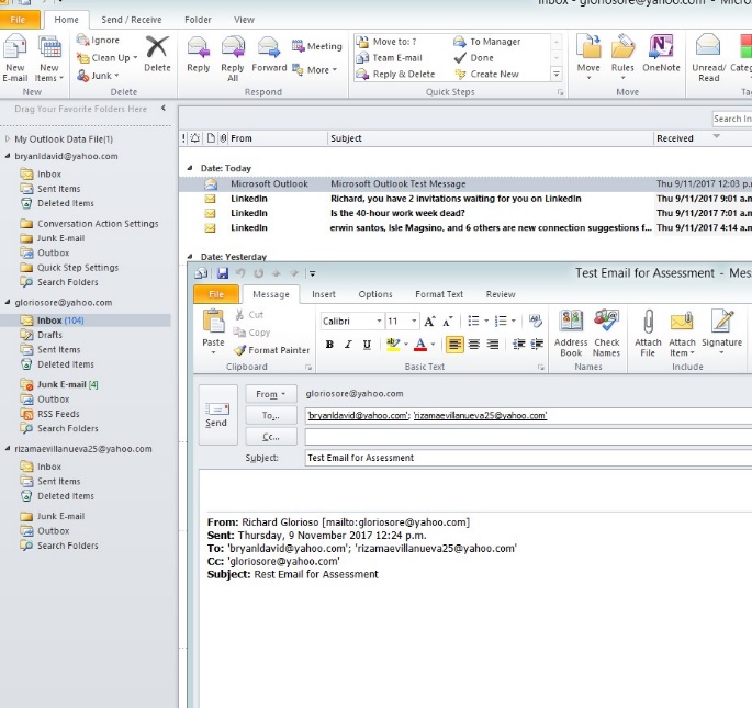
Figure 4.18 email test
- The test is currently progressing since the email will be sent to the client.

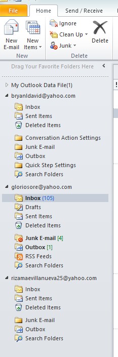
Figure 4.19 MS outlook dashboard
- Microsoft outlook test message in the Yahoo mail website.
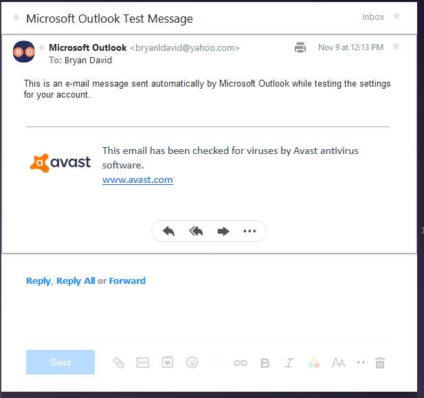
4.20 Yahoo mail
- Test email for the client to client email server
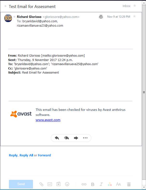
Figure 4.21 client to client email server
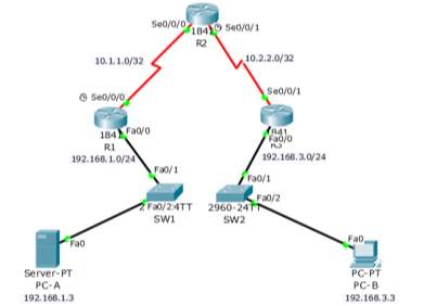
Task 5 Site-to-site VPN
Using VPN for the router in CISCO network provides more secured connection of transmitting data over public network. It can reduce the overpriced costs of leased lines. For the site-to-site VPNs it will provide a tunnel using IPsec between two branches of offices. Another use of site to site VPN is the remote access for the client and server for small offices.
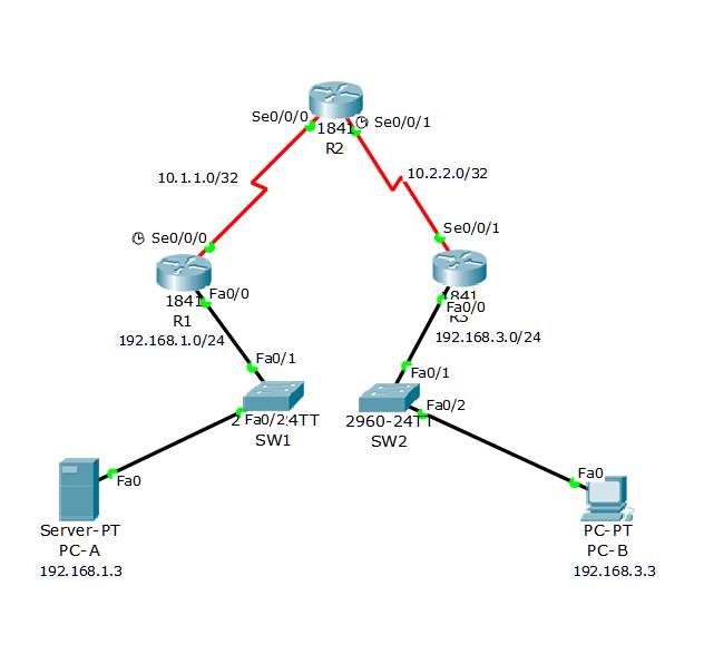
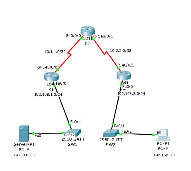
Site to site VPN topology
| Device | Interface | IP Address | Subnet Mask | Default Gateway | Switch Port |
| R1 | FA 0/1 | 192.168.1.1 | 255.255.255.0 | N/A | SW1 FA0/1 |
| S0/0/0 (DCE) | 10.1.1.1 | 255.255.255.252 | N/A | N/A | |
| R2 | S0/0/0 | 10.1.1.2 | 255.255.255.252 | N/A | N/A |
| S0/0/1 (DCE) | 10.2.2.2 | 255.255.255.252 | N/A | N/A | |
| R3 | FA0/0 | 192.168.3.1 | 255.255.255.0 | N/A | SW2 FA0/1 |
| S0/0/1 | 10.2.2.1 | 255.255.255.252 | N/A | N/A | |
| PC-A | NIC | 192.168.1.3 | 255.255.255.0 | 192.168.1.1 | SW1 FA0/2 |
| PC-B | NIC | 192.168.3.3 | 255.255.255.0 | 192.168.3.1 | SW2 FA0/2 |
Router 1 Configuration
hostname R1
!
cryptoisakmp policy 10
encraes 256
authentication pre-share
group 5
lifetime 3600
!
cryptoisakmp key cisco123 address 10.2.2.1
!
cryptoipsec security-association lifetime seconds 1800
!
cryptoipsec transform-set 50 esp-aes 256 esp-sha-hmac
!
crypto map CMAP 10 ipsec-isakmp
set peer 10.2.2.1
setpfs group5
set security-association lifetime seconds 900
set transform-set 50
match address 101
!
interface FastEthernet0/0
ip address 192.168.1.1 255.255.255.0
duplex auto
speed auto
!
interface Serial0/0/0
ip address 10.1.1.1 255.255.255.252
clock rate 64000
crypto map CMAP
!
routereigrp 100
network 192.168.1.0
network 10.1.1.0 0.0.0.3
no auto-summary
!
access-list 101 permit ip 192.168.1.0 0.0.0.255 192.168.3.0 0.0.0.255
!
line con 0
exec-timeout 5 0
password 7 0822455D0A165445415F59
logging synchronous
login
!
linevty 0 4
exec-timeout 5 0
password 7 0822455D0A165445415F59
login
!
end
Router 2
hostname R2
!
interface Serial0/0/0
ip address 10.1.1.2 255.255.255.252
!
interface Serial0/0/1
ip address 10.2.2.2 255.255.255.252
clock rate 64000
!
routereigrp 100
network 10.1.1.0 0.0.0.3
network 10.2.2.0 0.0.0.3
no auto-summary
!
end
Router 3
hostname R3
!
cryptoisakmp policy 10
encraes 256
authentication pre-share
group 5
lifetime 3600
!
cryptoisakmp key cisco123 address 10.1.1.1
!
cryptoipsec security-association lifetime seconds 1800
!
cryptoipsec transform-set 50 esp-aes 256 esp-sha-hmac
!
crypto map CMAP 10 ipsec-isakmp
set peer 10.1.1.1
setpfs group5
set security-association lifetime seconds 900
set transform-set 50
match address 101
!
interface FastEthernet0/0
ip address 192.168.3.1 255.255.255.0
duplex auto
speed auto
!
interface Serial0/0/1
ip address 10.2.2.1 255.255.255.252
crypto map CMAP
!
routereigrp 100
network 10.2.2.0 0.0.0.3
network 192.168.3.0
no auto-summary
!
access-list 101 permit ip 192.168.3.0 0.0.0.255 192.168.1.0 0.0.0.255
!
line con 0
exec-timeout 5 0
password 7 0822455D0A165445415F59
logging synchronous
login
!
linevty 0 4
exec-timeout 5 0
password 7 0822455D0A165445415F59
login
!
End
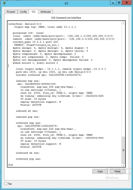
Check:
Router 1
As you could see in the CLI of the R1 all the connection of the inbound and outbound is ACTIVE
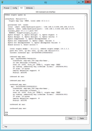
Router 3
As you could see in the CLI of the R3 all the connection of the inbound and outbound is ACTIVE
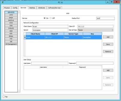
Task 6 Radius Server AAA
For basic authentication, AAA or the Authentication, authorization and accounting can be configured to access the local database for client logins. It will be difficult since it must be configured in every router. To take full advantage of the AAA, radius server AAA will be used. When the client attempts to login in the router, the router will show the router references to the external server database for verification that the client is using a valid username and password.
Topology for the radius Server AAA
| Device | Interface | IP Address | Subnet Mask | Default Gateway | Switch Port |
| R1 | FA0/1 | 192.168.1.1 | 255.255.255.0 | N/A | S1 FA0/5 |
| S0/0/0 (DCE) | 10.1.1.1 | 255.255.255.252 | N/A | N/A | |
| R2 | S0/0/0 | 10.1.1.2 | 255.255.255.252 | N/A | N/A |
| S0/0/1 (DCE) | 10.2.2.2 | 255.255.255.252 | N/A | N/A | |
| R3 | FA0/1 | 192.168.3.1 | 255.255.255.0 | N/A | S3 FA0/5 |
| S0/0/1 | 10.2.2.1 | 255.255.255.252 | N/A | N/A | |
| PC-A | NIC | 192.168.1.3 | 255.255.255.0 | 192.168.1.1 | S1 FA0/6 |
| PC-C | NIC | 192.168.3.3 | 255.255.255.0 | 192.168.3.1 | S3 FA0/18 |
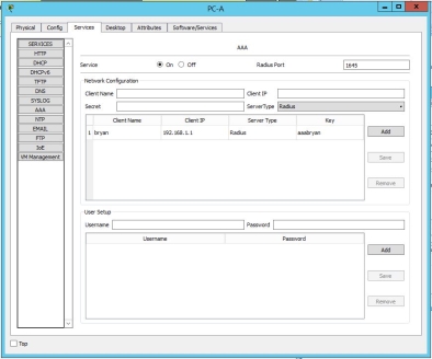
For the Radius server AAA, you can simply configure the users and keys from host that will use for authentication.
Router Configuration
Router 1
hostname R1
!
enable secret 5 $1$mERr$WvpW0n5HghRrqnrwXCUUl.
!
aaa new-model
!
aaa authentication login default group radius none
!
no ip cef
no ipv6 cef
!
no ip domain-lookup
!
spanning-tree mode pvst
!
interface FastEthernet0/0
ip address 192.168.1.1 255.255.255.0
duplex auto
speed auto
!
interface Serial0/0/0
ip address 10.1.1.1 255.255.255.252
clock rate 64000
!
router eigrp 100
network 192.168.1.0
network 10.1.1.0 0.0.0.3
no auto-summary
!
ip classless
!
ip flow-export version 9
!
radius-server host 192.168.1.3 auth-port 1645 key ciscoaaapass
!
line con 0
exec-timeout 5 0
password 7 0822455D0A165445415F59
logging synchronous
!
line vty 0 4
exec-timeout 5 0
password 7 0822455D0A165445415F59
!
end
Verification
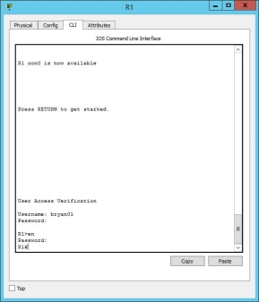
In the running configuration, the router will connect to the radius server for verification in the login console oof the router.
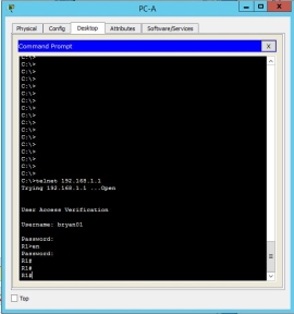
Using telnet, the client computer could connect to the router using RADIUS authentication.
Task 7 TACACS + Server AAA
TACACS or the Terminal Access Controller Access-Control System Plus is a protocol from CISCO systems and was released I 1993. TACACS+ don’t implements transmission control. Compared to the Radius, which encrypts only the user’s password as it travels from one client to another client. All other information in Radius will be able to see so it is vulnerable compared to TACACS+. In TACACS+, it encrypts all information including all other information traveling in the network.
Topology for the TACACS+ server AAA
TACACS+ configuration
hostname R2
!
enable secret 5 $1$mERr$WvpW0n5HghRrqnrwXCUUl.
!
Username bryan secret 5 $1$mERr$WvpW0n5HghRrqnrwXCUUl.
!
interface Serial0/0/0
ip address 10.1.1.2 255.255.255.252
!
interface Serial0/0/1
ip address 10.2.2.2 255.255.255.252
clock rate 64000
!
router eigrp 100
network 10.1.1.0 0.0.0.3
network 10.2.2.0 0.0.0.3
no auto-summary
!
tacacs-server host 192.168.1.3 key tacacspass
!
login local
!
line aux 0
!
line vty 0 4
!
end
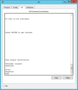
Verification:
This router will use TACACS+ on server 192.168.1.3 and the information inputed on the username and password will be verified.
Task 8 Vulnerability Assessment using GFI Languard
GFI Languard is used for scanning network security and patching management solution. It provides a complete platform of your network setup, risk analysis and maintains a secure and compliant network. This process includes scanning the network to discover all your devices connected in the network including mobile devices and search for security issues. All devices can be managed either by performing remotely with agent or none. For a remote agentless scan, specify first your target devices scanning profile that indicates what to look for, enter proper authorizations. [5] GFI. (n.d.).
Steps on how to setup and use GFI Languard:
1. Alerting Options of GFI Languard can be found by logging to the console.
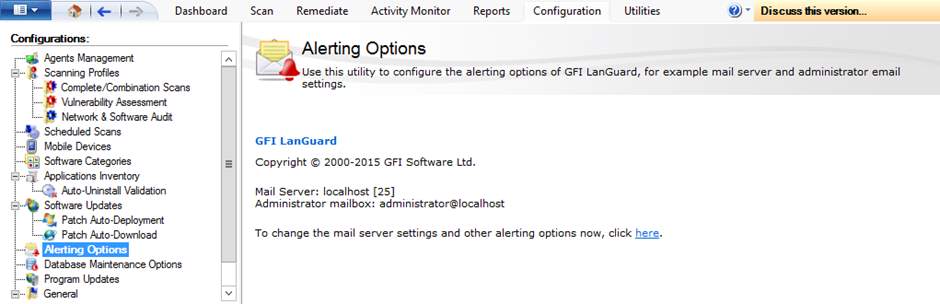
Figure 8.1 Alerting option configuration
- Setup an email address where the alert will be coming from and also specify a recipient.
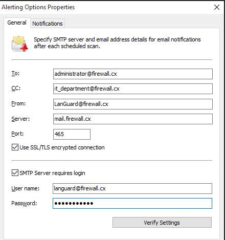
Figure 8.2 General setup for email addresses
- Next is the vulnerability assessment settings. It will provide an option which profile will be scanned and activate high security vulnerabilities.
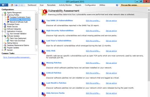
Figure 8.3 Profile options for vulnerability assessment
- The profiles selected can be edited so that administrators can add and remove different items that would be included or excluded on the scan.
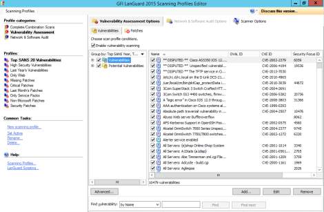
Figure 8.4 Vulnerabilities profiles
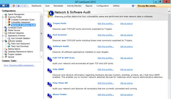
Figure 8.5 Each profile can be further customized to best fit the requirement of the organization.
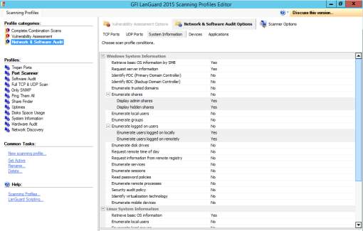
Figure 8.6 Scanning options for network and software audit
- Scheduling a scan for GFI Languard makes vulnerability scanning an easy for administrators. It offers a Scheduled Scan option to perform scan at specific date and time.
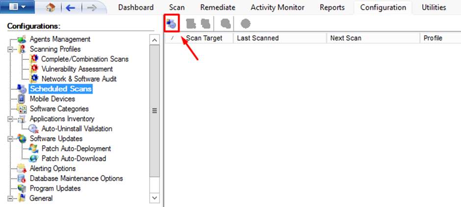
Figure 8.7 Performing scheduled scan
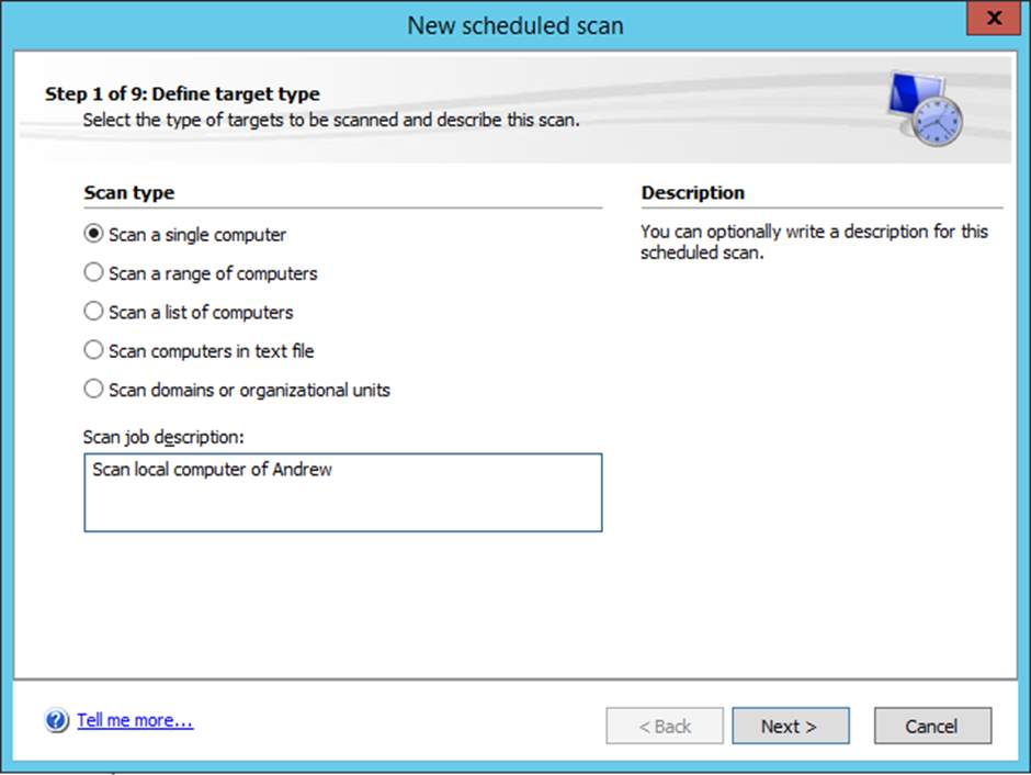
Figure 8.8 Type of scan desired
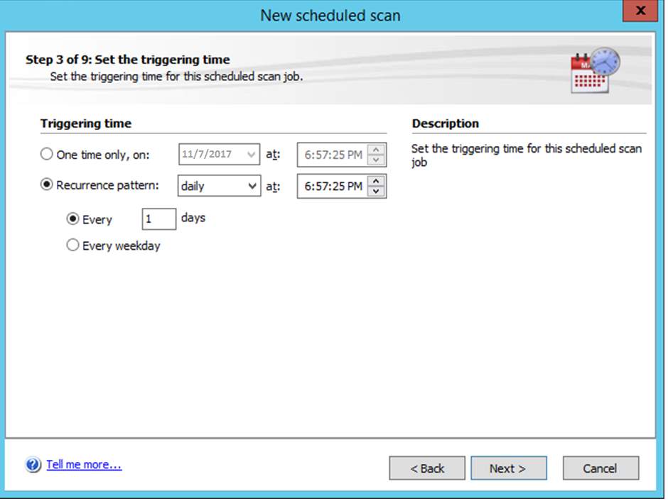
Figure 8.9 specific day and time to avoid affecting user’s productivity
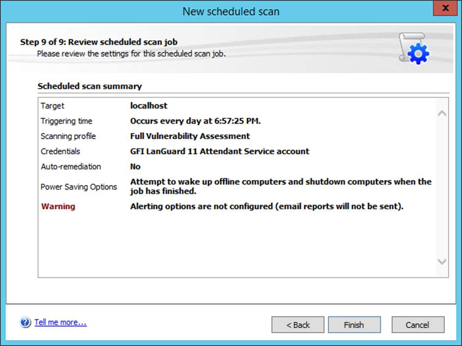
Figure 8.10 Successful scheduled scan
Task 9 NVD – National Vulnerability Database
NVD is the U.S. government source of standards from NIST – National Institute of Standards and Technology based on vulnerability management data characterized using the Security Content Automation Protocol (SCAP). The data from NVD enables automation of security administration, vulnerability dimension, and acquiescence. NVD includes database of checklists in security and software flaws, malfunctions, merchandise names, and impact metrics. [6] NVD. (2017, October).
Here are 5 vulnerabilities that are listed on the website:
1. CVE-2017-16543 Detail
- It is for Zoho ManageEngine Applications Manager 13 that permits SQL injection via GraphicalView.do using crafted viewProps yCanvas field.
| Source: | MITRE | Last Modified: | 11/05/2017 |
| US-CERT/NIST | Original release date: | 11/05/2017 |
- CVE-2017-16545 Detail
- It is the ReadWPGImage purpose in coders/wpg.c in GraphicsMagick 1.3.26 malfunction to validate colormapped images and allows remote attackers to have a DoS or probably have unnamed other causes via malformed image.
| Source: | MITRE | Last Modified: | 11/05/2017 |
| US-CERT/NIST | Original release date: | 11/05/2017 |
- CVE-2017-16546 Detail
- It is the ReadWPGImage purpose in coders/wpg.c in ImageMagick 7.0.7-9 malfuntion to validate the colormap index in a WPG palette and allows remote attackers to cause DoS or probably have unnamed other causes via malformed file.
| Source: | MITRE | Last Modified: | 11/05/2017 |
| US-CERT/NIST | Original release date: | 11/05/2017 |
- CVE-2017-16547 Detail
- It is the DrawImage purpose in magick/render.c in GraphicsMagick 1.3.26 malfuntion to look for popup keywords that are liked with push keywords and allows remote attackers to cause a DoS or perhaps have unnamed causes via a crafted file.
| Source: | MITRE | Last Modified: | 11/06/2017 |
| US-CERT/NIST | Original release date: | 11/06/2017 |
- CVE-2017-16548 Detail
- It is a receive_xattr function in xattrs.c for rsync 3.1.2 and 3.1.3-development that didn’t verify a trailing with ‘
Cite This Work
To export a reference to this article please select a referencing stye below:
Related Services
View all


DMCA / Removal Request
If you are the original writer of this assignment and no longer wish to have your work published on UKEssays.com then please click the following link to email our support team:
Request essay removal