Investigation of JTAG and ISP Techniques for Forensic Procedures
Info: 17822 words (71 pages) Dissertation
Published: 26th Nov 2021
Tagged: Forensic Science
Abstract
This thesis is focusing on JTAG and ISP physical acquisitions techniques. These techniques were created from manufactures to test PCBs and repair devices but they are being used as a forensic technique to acquire the data from a device. The aim is to give an overview of these techniques from a forensic point of view and in addition to some other tests will try to prove that are forensically equivalent to any other method. The first test will focus on showing the differences on the different types of acquisition by comparing the results of a forensic analysis of the same device using Cellebrite UFED Touch and Physical Analyzer. The second test will try to prove that all physical acquisitions are equivalent by comparing the acquired data from the same device with two different methods. Finally, the last test will focus on the examination of the content of an encrypted device to show if it is possible to find evidences.
Keywords: Android, Forensic, JTAG, ISP, eMMC, Acquisition, Physical, Logical
CERCS: P170,Computer science, numerical analysis, systems, control
Abbreviations and Definitions
| JTAG | Joint Test Action Group |
| ISP | In-System Programming |
| TAP | Test Access Point |
| OS | Operating System |
| YAFFS2 | Yet Another Flash File System 2 |
| ADB | Android Debug Bridge |
| CWM | ClockWorkMod |
| TWRP | Team Win Recovery Project |
| PCB | Printed Circuit Board |
| ATF | Advanced Turbo Flasher |
| SWGDE | Scientific Working Group on Digital Evidence |
| SSDDFJ | Small Scale Digital Device Forensics Journal |
Table of Contents
Click to expand Table of Contents
1 Introduction
2 Background
2.1 Android File System and Partition Layout
2.2 Digital Forensic
2.3 Data Acquisition
2.3.1 Logical Acquisition
2.3.2 Physical Acquisition
2.3.3 Cellebrite UFED Touch
2.4 Best Practices
2.4.1 Handling Evidence
2.4.2 Equipment Preparation
2.4.3 Data Acquisition
2.4.4 JTAG
2.4.5 Documentation
2.4.6 Archive
2.5 Related Work
3 Test Cases Overview
3.1 Data acquisition types comparison with Cellebrite UFED Touch
3.2 Physical acquisition techniques comparison: UFED Touch vs “dd” command
3.3 Working with Encrypted Device
3.4 eMMC TAP Identification
3.5 ISP
3.6 JTAG
4 Testing and Comparing Forensic Acquisition Techniques with Step-by-Step Guide
4.1 Data acquisition types comparison with Cellebrite UFED Touch
4.2 Cellebrite UFED Touch and dd Physical memory dump Comparison
4.3 Encrypted device
4.4 eMMC Test Point Identification
4.4.1 ATF 4in1 Adapter setup
4.4.2 ATF software setup
4.4.3 Test Points Identification
4.5 ISP Acquisition
4.6 JTAG Acquisition
4.6.1 JTAG Test Access Points
4.6.2 JTAG Acquisition Process
5 Conclusion and Future Work
6 References
Appendix
I. Hash Comparison Python Script
II. Media Files and Application Setup
III. Cellebrite UFED Touch Logical, File System and Physical Acquisition
IV. Physical Acquisition with “dd” command.
V. License
1 Introduction
Smartphones have become an integral part of people’s daily life; in 2014, smartphone users were 1.57 billion while in 2016 this number increased to 2.1 billion and by 2020 it is expected to go up to 2.87 billion, globally [1]. Smartphones are pocket-sized computers in which you can browse the Internet, chat, send emails, create and read documents and books, use GPS to navigate, keep notes and a lot of other functions. When these valuable functions are combined with the fact that people tend to carry their phones everywhere, smartphones become a goldmine of evidences in criminal cases.
The plethora of artefacts in devices like smartphones created the need of a science that its main goal is to examine these devices for evidences and report them in a clear way for later use in court, thus mobile forensics emerged, which is a sub-branch of the main science of digital forensics. Mobile forensics is relatively a new area but it is growing fast as forensic examiners are dealing with mobile devices more often than before.
Mobile forensics is the science dedicated to analyzing mobile devices for evidences. The forensic process consists of the collection of evidences, data acquisition, analysis of the data and report the evidences. In mobile forensics, data acquisition and analysis it can be one step or two different steps depends on the method and technique used. The methods for data acquisition can be divided in three types: logical, file system and physical acquisition. Logical acquisition is a “bit-by-bit” copy of logical storage objects (e.g. files) that reside on a logical storage while physical acquisition is bit-by-bit copy of the physical storage (e.g. flash memory), as quoted from Wikipedia [2]. File system acquisition can provide information for files that are deleted but not overwritten if the device allows file system access. Each type of acquisition has a variety of techniques for data acquisition such as “nandroid” backup (only for Android devices) and “logical acquisition” using “UFED Touch” for the logical acquisition and JTAG[1], ISP[2], chip-off or “dd” command for the physical acquisition. The examiner has to choose which method will be used based on the case’s needs, the available tools, device(s) for analysis and also his skills.
The purpose of this thesis is to examine JTAG and ISP acquisition techniques and provide information regarding the process of the acquisition as well as about the tools an examiner needs in order to use these acquisition techniques. Moreover, it will show step by step the process of how to find the eMMC TAPs[3] needed for ISP acquisition. Finally, two comparisons will be held, one between different types of acquisition and one between different techniques for the same type (physical) of acquisition. The first comparison will show the differences on the evidences found from different acquisition while the second one will show if the images obtained with different techniques are equivalent.
This thesis is focusing on the data acquisition part of the forensics process and not on the post-acquisition analysis, as a high amount of research has been done already. For the purposes of this thesis two devices will be used, the Samsung Galaxy S4 I9505 using Android 5.1 and the Nokia Lumia 635. The Nokia device will be used for eMMC TP identification and ISP acquisition while the Samsung device will be used to perform different types of data acquisition such as logical, file system and physical. For physical acquisition, more than one techniques will be used. Finally, a physical acquisition of the device being encrypted will be performed to check if this type of acquisition can provide any evidences or not. The aim of this thesis is to examine if JTAG and ISP acquisitions can be used as a forensic technique and also provide the following:
- A method for finding eMMC TPs for ISP acquisition.
- A method on how to perform ISP acquisition with ATF flash box.
- A method on how to perform JTAG acquisition with Riff Box.
- Information regarding the examination of encrypted device’s memory dump.
- Comparison of evidences that can be found with logical, file system and physical acquisition.
2 Background
Before the experiment starts, some theoretical background is required that covers what forensic is, information about acquisition types and techniques, best practices and work that has been conducted.
2.1 Android File System and Partition Layout
Android is the dominant OS[4] for smartphones on the market with 86.8% of global market share as it was measured on the third quarter of 2016 [3]. Android uses a variety of file systems, the partition which stores user’s data, the only forensic valuable partition, uses EXT, FAT32 and YAFFS2[5] [4]. Proprietary file systems can be found as well such as Samsung’s RFS file system. Also, virtual file systems, that are not written to any physical device, exist in Android such as “proc” (information for kernel, processes and configuration parameters) and “rootfs” (where kernel mount root file system at startup). The “/proc/filesystem” file provides information about the file systems supported by Linux kernel and by extension from Android.
Partition layout differs between Android devices made by different manufacturers but some partitions are common in all devices, these partitions are [4]:
Boot Loader
Stores boot loader program.
Boot
Contains Linux kernel and RAMdisk. Without it, the device can boot only in
recovery mode.
System
Contains the Android OS only, not the kernel and RAMdisk.
Data or userdata
Contains user’s data such as photos, music, applications etc.
Cache
Contains frequently accessed data and app components.
Recovery
Contains a second complete Linux system with kernel and special recovery binary used to boot in recovery mode. Useful for repairing a device if the boot partition is destroyed or flashed with wrong kernel.
Radio
Contains baseband image, responsible for telephony activities.
This is the external card and not a partition from the internal memory.
These are the main partitions of an Android device but more partitions can be found between devices of different manufactures, the most valuable partition from a forensic standpoint is “data” or “userdata” partition.
2.2 Digital Forensic
Forensic science consists of several branches and one of them is digital forensics with its main purpose being the recovery and investigation of material found in digital evidences [5]. Digital forensics can be divided further into sub-branches such as forensic data analysis, computer, network and mobile forensics.
The process from the seizure of an exhibit, exhibit is the devices for investigation in legal terminology, until the creation of a report is called digital forensics process [6].
The stages of this process are:
Seizure
Digital forensic technicians gather the exhibits from the crime scene.
Acquisition
Exact sector or forensic duplicate of the media is created for analysis. The analysis should never be done in the original device, only in case of live analysis at the crime scene.
Analysis
Digital forensic examiner performs analysis of the exhibits to gather evidences using different methods and tools.
Report
Report with the findings of the analysis.
The personnel responsible for this process can be separated broadly in two levels, the digital forensic technicians and the digital forensic examiners [5]. Technicians are responsible to gather or process evidences in crime scene and sometimes they may have to perform a “live analysis” of evidence. Technicians should be trained to handle the exhibits appropriately. Examiners on the other hand specialize in only one area.
2.3 Data Acquisition
In mobile forensics, data acquisition is divided in different levels/types. According to SWGDE Best Practices for Mobile Phone Forensic [7], these levels are:
- Manual: Use of the device itself to look for evidences manually.
- Logical: Extraction of file system’s portion.
- File System: Provides access to the file system.
- Physical (Non-Invasive): Physical acquisition of a phone’s data without disassembling the phone.
- Physical (Invasive): Physical acquisition of a phone’s data that requires disassembly of the device to access the PCB (JTAG/ISP).
- Chip-off: Removal of the chip from the PCB for analysis.
- MicroRead: High-power microscope is used for a physical view of the electronic circuitry of memory.
This thesis is focusing mostly on level 5 data acquisition of mobile’s memory.
2.3.1 Logical Acquisition
Logical acquisition is a bit-by-bit image acquisition of logical storage objects that reside on a logical storage or, in other words, the allocated data. This type of acquisition is performed by utilizing a designated API [8]. Some logical acquisition techniques are explained in this paragraph. Note that these two techniques are available only to Android devices.
2.3.1.1 ADB Pull
ADB[6] is a command line tool found in Android SDK, which allows the user to communicate with an Android device [4]. ADB provides lots of commands [9] but the most useful from the forensic standpoint is the “pull” command because it is used to get data from the connected device. The prerequisite to use this command, and any other command of the ADB, is to have the developer’s mode and USB debugging option enabled on the device. If the device has not root access, the ADB daemon on the device runs with shell privileges, similar to non-root access on Linux terminal, which has as a result limited access to forensically relevant files. An example of useful files that can be pulled are unencrypted apps, “tmpfs” file system, which may include user’s data and other readable directories. When the device is rooted, or uses a custom ROM then it is easy to pull everything form the device.
2.3.1.2 Backup Analysis
The backup analysis techinque relies on the analysis of the user’s backup [4]. During the first years of its use, Android did not provide any backup mechanism for user’s data which had as a result Android users relying on third-party applications to backup their data. The backup was usually stored in SD card or in the Cloud. This backup usually consists of user’s files such as pictures, videos and documents, but for rooted users some applications can also back application’s data as well. In addition, rooted users have a more powerful technique for backing up their data that is called “nandroid“. Nandroid backup can be achieved in two different ways; either by booting the device in recovery mode, custom recovery is needed with the two most known and used CWM[7] and TWRP[8], or using an application such as “Online Nandroid Backup“, both options require root [10]. Nandroid backup is creating an image that contains user’s data and system files as well.
2.3.2 Physical Acquisition
Physical acquisition is a bit-by-bit copy of the physical storage and it can be invasive, JTAG, ISP or Chip-off, or non-invasive, with the use of “dd” command. The difference, from the forensic point of view, between physical and logical acquisition is that in physical acquisition deleted files may be recovered and the slack space can be examined. A brief comparison of the evidences that can be found with these techniques can be seen on the paragraph 4.1.
2.3.2.1 JTAG
IEEE 1149.1 [11] is the Standard Test Access Port and Boundary-Scan architecture for TAP used for testing printed PCBs[9] using boundary scan is known as JTAG. JTAG was created for testing purposes but in the recent past it started being used in mobile forensic science to perform a low level raw content acquisition of the flash memory. JTAG is a non-destructive invasive method which means that the device needs to be disassembled (invasive) but after the acquisition it can be used again (non-destructive). The JTAG process requires a connection of a hardware, flash box, to the device’s PCB test access points via solder, Molex cable or jig and a computer [12].
Most times soldering will be needed so tools and hands-on experience on micro-soldering is needed. The most known flash box that supports JTAG is Riff box, other boxes are ATF[10] and Z3X. JTAG is a technique that utilizes the processor for memory acquisition. The process requires firstly to connect device’s JTAG TAPs with a flash box, the box to a computer and lastly to setup flash box’s software, When everything is connected and the software is setup correctly the flash box will instruct the processor via the test access points to acquire the raw data stored on the chip, then the processor will reply with the data which will travel back following the same path from memory to the processor and out from the TAPs to JTAG box and finally to the computer; this process describes steps 3 and 4 from the JTAG acquisition process [13]. The JTAG acquisition process consists of:
- Device disassembly
- Find TAPs on the PCB
- Connect JTAG Box, which is connected to the computer, to the corresponding TAP on the PCB
- Acquire chip image with the use of JTAG’s Box software
- Disconnect the JTAG and assemble the device
JTAG’s main drawback is that not all devices are JTAG-able and this can happen, as Jenise Reyes-Rodriguez explains on his presentation, because [13]:
- Device may not have TAPs
- Device is not supported by JTAG box
- Processor may be supported but:
- TAPs configuration has not been discovered (iOS devices)
- TAPs may be disabled or shut down by OS
- Fuse in processor may be bad
If the TAPs are known but the device is not supported, the examiner can look for the device’s processor and use another’s device profile which uses the same processor. If TAPs are not known, the examiner can try to identify them by probing each TAP on the PCB until he has all the TAPs needed, tools and software is needed. The TAPs needed for JTAG are the following, as described from SWGDE[11] [14]:
- TDI (Test Data Input): shows the data shifted into the device’s test or programming logic.
- TDO (Test Data Output): shows the data shifted out of the device.
- TMS (Test Mode Select): samples at the rising edge of TCK to determine the next state.
- TCK (Test Clock Input): synchronizes the internal state machine operations.
- TRST (Test Reset): resets the TAP controller’s state machine to a known state.
Other TAPs used for JTAG may include:
- GND (Ground): may be pad or known ground source on the device
- RTCK (Return Test Clock): Listens for the return signal to achieve adaptive clocking.
- SRT (System Reset): Power cycles the device.
- VREF (Voltage Reference: Indicates signal levels.
- VCC (Voltage collector): Supplies powers.
For JTAG TAPs if flash box’s software does not provide them, the examiner should search on the internet or in forums with the two following being the most known http://forum.gsmhosting.com/ and http://www.unlockforum.com/; as the information on these forums is based on the users everything should be tested in a second device before use it in a real case. The TAPs also can be found by probing TAPs on the PCB until everything is known. Finally, information regarding the JTAG test access points can be found on device’s schematics but these files are confidential and manufacturer should be contacted in order to acquired them.
2.3.2.2 ISP
ISP is an acquisition technique similar to JTAG with its main difference being that ISP connects directly to the eMMC or eMCP flash memory, it bypasses the processor. In ISP, as in JTAG, the examiner needs to know the TAPs that connects to the memory and a flash box. The process requires firstly to connect eMMC TAPs with a flash box that supports eMMC read/write operations, connect the flash box with a computer and setup the flash box’s software. When everything is connected, the software is setup correctly and the connection between flash box and eMMC has been established the content of the memory can be read.
Finding the TAPs for the eMMC is the same as mention in paragraph 2.3.2.1 for JTAG, if flash box’s software does not provide them, then internet and forums, if none of these works then the examiner can find them manually by probing each TAP on PCB and he knows all TAPs needed, for this process ATF box and an adapter is needed as well as a second device identical to the original one for testing purposes, more details on paragraph 4.4. Finally, information regarding the eMMC TAPs can be found on device’s schematics. As in ISP acquisition the connection is directly to the memory chip the acquisition process is faster than JTAG. Also, it can be used when a device is not JTAG-able. The TAPs needed are the following, as described from Kingston Technology in more details in eMMC Specification Ver 4.4, 4.41 & 4.5 [15]:
- CMD: Command in/ Response out
- DATA0: Data input / output
- CLK: Clock
- VCC: Supply voltage for Core (3.3V)
- VCCQ: Supply voltage for I/O (1.8 – 3.3V)
- GND: Ground
It should be mentioned that ISP acquisition applies to any eMMC or eMCP flash memory, thus is not limited to phones but to any device utilizing these memories, such as SD cards.
2.3.2.3 Chip-off
Chip-off is an advanced technique for data extraction that requires firstly to remove the chip from the device and then specialized equipment to mount the chip and create an image of the raw data [16]. Chip-off is not limited only to mobile phones but it can also be used in other devices that utilize flash memory, such as GPS and vehicle components. The chip-off process consists of four steps:
- Remove chip from the device.
- Clean and repair the chip.
- Image acquisition with the use of specialized equipment
- Analysis of the image with standard forensic tools.
This technique should be used only if there is no other alternative. Chip-off not only requires expensive equipment, but the examiner should be experienced and skilled as well. Apart from the method with the expensive equipment there is another way to read the memory but is not recommended. This method is actually an ISP acquisition but instead of connecting on device’s TAPs the flash box connects directly on TAPs on the chip. As the chip can be destroyed during the chip-off process it should be done only by experts.
2.3.2.4 dd command
The “dd” command method is a non-invasive physical acquisition technique which makes use of Linux “dd’ command. This command is used to copy and convert files but forensics examiners are using it to create bit-by-bit images of drives [17]. As Android is based on Linux, if the device meets some requirements this command can be used to acquire a partition or a full memory dump, these requirements are that the device must be rooted with BusyBox installed and the “developer’s mode with USB debugging” option must be enabled. The process to root a device differs between devices.
If these requirements are fulfilled, then the examiner has to boot the device into custom recovery mode and connect the device to a computer, then again with the ADB tool should start looking for the partition he wants to acquire; this can be done by inspecting the “/proc/partitions” file for information about the partitions on the device, for Samsung Galaxy S4 partitions can be seen in Figure 1. For full disk image, the first (root) block should be chosen. In case the examiner does not need the entire memory and wants a specific partition, he will have to look for information that maps each block to a name; the “by-name” directory usually contains this information as in Figure 2. It should be mentioned that not all devices have this directory and it is not on the same path on all devices.
Other commands that the examiner may use to find information for the partitions are “mount” or “cat /proc/mounts”, “cat /proc/emmc”, “cat /proc/mtd” and finally “cat /proc/yaffs” for older devices and “fstab” file (usually called fstab. ) for newer devices. Some information regarding the process can be seen in paragraph 4.2 Once, the examiner has the name of the block-device (partition) the following commands should be executed:
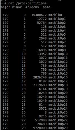
Figure 1 Samsung Galaxy S4 partitions
Terminal 1
- adb forward tcp:1111 tcp:1111
- adb shell
- /system/xbin/busybox nc -l -p 1111 -e /system/xbin/busybox dd if=/dev/block/mmcblk0
Terminal 2
- adb forward tcp:1111 tcp:1111
- nc 127.0.0.1 1111 | pv -i 1> mmcblk0.raw
Important notes:
- For Windows systems, “Netcat” and “pv” from Cygwin should be installed
- Commands for terminal 2 should be executed in Cygwin terminal.
- Any port can be used as long as it is the same in all commands.
- The path for BusyBox may differ, depending on if the folder BusyBox was installed; “/system/xbin” is the default folder.
- The path for the block may be different between devices
- Block name should be the name of the partition for extraction, root one if full memory needed.
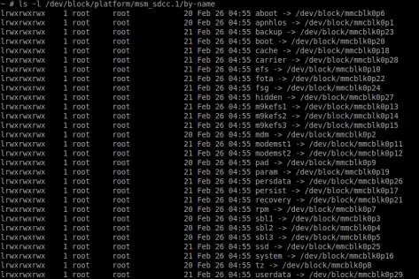
Figure 2 Samsung Galaxy S4 partitions by name
2.3.3 Cellebrite UFED Touch
Cellebrite is a company that has expertise in the field of mobile data technologies; one of the tools they have created is the UFED Touch. Their latest product is UFED Touch 2, which is a portable device for forensic analysis of devices such as smartphones and GPS. UFED Touch supports all three types of data acquisition logical, file system and physical [8]. For logical acquisition, UFED Touch loads the appropriate API to the device and then makes read-only requests to obtain data such as text messages and pictures. Logical is the fastest acquisition method but the time it varies, based on the available files on the device.
File system acquisition is similar to the logical one but it uses different built-in protocols for the acquisition of the file system. In some cases, to obtain files that are not accessible through the API, this method relies on available device backup files. Files that might be found with file system acquisition are user deleted and hidden data from SQLite databases. As in the logical acquisition, the time for this method depends on the files stored on the device.
For a physical acquisition, UFED uses the device in “rescue mode” or “download mode” which allows the insertion of code, bootloader, into the RAM during start-up. It is most likely that UFED makes use of the “dd” command to get a memory dump; this is just a hypothesis though and it has not been verified. Cellebrite uses bootloaders that have been made by them specifically for the devices they support. The code consists of read actions only to extract data without altering anything. The read data is sent to the UFED Touch which then writes it on a binary file on the computer or a removable memory such as an SD card. This is the most time-consuming method and the time needed is based solely on the size of the memory.
There are cases in which UFED may need to temporary root the device or permanently change the device’s bootloader in order to be able to get an image of the memory. These methods are leaving footprints and may overwrite data in unallocated space but they can be admissible in the court if documented properly.
2.4 Best Practices
Best practices are rules that everyone who handles exhibits should follow. These rules are non-binding but it is highly recommended for everyone to follow them in order to eliminate possible objections in the court and also to eliminate the chances of an evidence not being admissible in the court. Best practices can be found at SWGDE. The relevant best practices for this thesis can be found in SWGDE Best Practices for Mobile Phone Forensics [7] and SWGDE Best Practices for Examining Mobile Phones Using JTAG [14].
2.4.1 Handling Evidence
Mobile phones, and any other device, apart from the digital evidences they may also have traditional evidences, such as finger prints and DNA, thus further analysis is needed. As OS gives us the opportunity to completely wipe memory remotely and in order to prevent any data alteration, the mobile phone should be isolated from the network (cellular and internet). The examiner should always take precautions for safety reasons and finally, the evidences should always be processed according to policy in order to maintain a chain of custody.
2.4.2 Equipment Preparation
Any tool or software used for data extraction and analysis of the evidence should be tested and verified before it can be used to ensure its performance. Documents related to software/hardware should be reviewed from time to time and also, they should be accessible. On this website http://www.cftt.nist.gov/, NIST validation reports for some tools can be found. The reports are about capabilities and limitations of the tools.
2.4.3 Data Acquisition
In data acquisition, the examiner should pay attention to some key points. Firstly, he has to keep isolated evidence from different devices to avoid cross-contamination. In addition, he has to document the mobile phone’s physical condition, as well as the data acquisition method. Finally, after the acquisition, he needs to verify that the data between the mobile phone and the acquired data are identical.
2.4.4 JTAG
As mentioned before, not all devices are JTAG-able and traditional forensics methods should be attempted first [14]. Some of the cases that JTAG is a good candidate are for damaged devices or devices that are password-protected, when “USB debugging” mode is disabled, when non-invasive acquisition is not possible or logical acquisition is insufficient.
2.4.4.1 Training
Examiners that perform JTAG acquisition should have proper training which covers topics such as boundary scanning overview, how to remove the PCB on mobile devices, soldering/de-soldering, TAPs identification, electronics and finally how to handle evidences and procedures in digital forensic.
2.4.4.2 JTAG Process
- Preparation
- Disassembly
- TAPs Identification
- Connectivity
- Configuration
- Extraction
- Preservation
- Hashing
2.4.5 Documentation
The organization sets the policies that the examiners must follow which should cover at least how to handle evidences, how to examine the information and report the findings.
2.4.5.1 Evidence handling
The documentation about evidence handling should include: copy of legal authority, chain of custody, photographs and detailed description of the devices and finally photographs of any visible damage and information regarding the packaging. Of course, the documentation is not limited to these topics only.
2.4.5.2 Examination
Any document regarding the examination of the evidences should be preserved according to policy and should provide enough information to the extent that enables another examiner to repeat the findings independently. It should also include tools and software used, as well as problems faced during the data acquisition (e.g. faulty cables).
2.4.5.3 Report of findings
The report of findings should include information regarding the purpose of the examination, the examiner’s information (e.g. name) and date, a detailed description of the examined device, other reports related to the examination and answers to the investigator’s specific requests. Moreover, the report should provide all information in a clear and concise manner and finally, it should be reviewed according to organizational policy.
2.4.6 Archive
Once a case is finished, all files related should be archived according to organizational policy and all applicable laws. In some cases, it may be necessary to archive the specific version of the tool used as well.
2.5 Related Work
A high amount of research has been done already regarding Android forensics. Most topics are covering either logical acquisition techniques or the post-acquisition analysis. The post-acquisition analysis can be focused, such as Vsevolod Djagilev’s thesis which focuses on finding evidences from chat applications in Android [18] or more generic, like a general guideline, such as an article about “Simplifying Cell Phone Examination” from SSDDFJ[12] [19]. Another research was focused on verifying if physical acquisition through recovery mode and JTAG maintains the integrity of the data comparing [20]; the results showed that the data integrity is maintained.
Andrew Hoog on his book “Android Forensics: Investigation, Analysis, and Mobile Security for Google Android” [4] has given plenty of information for Android Forensics, such as Android supported file systems, acquisition techniques, Android history et cetera. When it comes to JTAG and ISP, the information from a forensic standpoint is limited, and the available sources are mostly from enthusiasts that utilize these techniques to repair devices, thus testing should be done before it can be used in a real case. Finally, as technology is moving forward in a very fast pace with new devices and new versions of Android being launched quite often, some of the previously conducted research may be already obsolete and some methods may not be applicable to this moment.
3 Test Cases Overview
This chapter will give a brief explanation of the tests which will be conducted on this thesis, the aim of each test and the expected results.
3.1 Data acquisition types comparison with Cellebrite UFED Touch
The first experiment will be a comparison of the evidences that can be found with the three types of data acquisition logical, file system and physical. This experiment will give an overview of the differences on the evidences that can be found with each method. The device which will be used is a rooted Samsung Galaxy S4 LTE (GT-I9505) with BusyBox installed and Android 5.0.1 and for the all data acquisitions will be taken with Cellebrite UFED Touch. Apart from the changes on the software of the device (custom recovery, root and BusyBox), the device was slightly used to send/receive e-mails and instant messages, browse the internet and copy/delete some media files. A full list of what was done to the device prior to acquisition can be found in the Appendix II. The experiment will start with logical acquisition which is the fastest and most common acquisition, then with the file system one and lastly with the most time-consuming physical acquisition. It is expected that logical acquisition will provide the least amount of evidences the while physical one will provide the biggest amount of evidences. Furthermore, with the physical acquisition it may be possible to find some of the deleted files which is not expected from the logical one.
3.2 Physical acquisition techniques comparison: UFED Touch vs “dd” command
This experiment it will compare a memory dump taken with the “dd” command and memory dump taken with UFED Touch exactly after the first one was finished. The aim of this test is to compare the outputs of these two techniques and check if different physical acquisition techniques are equivalent. It is expected to be, and taking into consideration the result of the research on user’s data integrity during acquisition of Android devices [20], it will be a verification that no matter which physical acquisition technique (Ufed Touch, JTAG, ISP or dd command) is being used the results will be the same and admissible in a court.
3.3 Working with Encrypted Device
For this test, the same device will be encrypted, then an image will be acquired using “dd” command and in the end, will be analyzed for evidences. The purpose of this experiment is to check if a physical acquisition of an encrypted device can provide any information when the device is encrypted.
3.4 eMMC TAP Identification
In order to perform ISP acquisition the examiner needs to know the TAPs that connects directly to the eMMC. There are few possible ways to find the pins needed for this operation and they have been mentioned on the paragraph 2.3.2.2. This paragraph will be dedicated to the method which uses ATF box’s eMMC finder module. ATF Nitro box will be used with “ATF-V2 4in1 Adapter for ATF Box” and ATF’s software version 12.67. The device which will be used for this test is “Nokia Lumia 635”. The aim of this test is to provide a method on how to perform TAP identification for the eMMC using ATF box in order to get a memory dump after.
3.5 ISP
This paragraph will be dedicated on memory acquisition utilizing the In-System Programming technique and it continues from where the previous paragraph stopped. How to perform and ISP acquisition with the use of ATF box will be explained and any problems that may appear during the procedure. Finally, the memory dump obtained will be loaded to UFED for forensic analysis.
3.6 JTAG
This paragraph will be dedicated to memory acquisition with JTAG, for the test Riff box and JTAG jig for Samsung S4 I9505 will be used. How to perform JTAG acquisition will be explained as well as any problems that may appear during the acquisition. Moreover, the file obtained will be compared to the ones obtained in the previous paragraph with UFED and “dd” command. It is expected of the files to be identical and provide the same information when scanned for evidences with forensic tools.
4 Testing and Comparing Forensic Acquisition Techniques with Step-by-Step Guide
This chapter is dedicated on the practical part of this thesis. In this chapter, the tests held in this thesis will be explained in details and a method on how to perform JTAG and ISP acquisition will be given. Finally, data acquisition types will be compare in order to show the differences on the evidences that can be found with each type.
4.1 Data acquisition types comparison with Cellebrite UFED Touch
Cellebrite UFED Touch supports a big number of devices, and not only smartphones, and different methods of data acquisition, these methods may not be available in all devices. What this paragraph will try to show is the outcome of these methods and a comparison of the evidences they can provide. As this is not the focusing point of this thesis the data acquisition process will be explained briefly and the comparison will not be in depth.
The data acquisition with UFED Touch is very simple and UFED Touch has step by step instructions on the screen. The steps for the acquisition are the following:
- Search and select the device on UFED Touch. If the device is not available then, it means that it is not supported.
- Choose the type of acquisition, Logical, File System, Physical.
At this point UFED Touch will provide all information needed for the connection with the device and the acquisition process.
- Setup the device according to the instructions on UFED Touch screen.
- Connect the device with the cable mentioned on the instructions. Cables comes with UFED Touch.
- Start the acquisition. Sometimes the acquisition might fail, in that case acquisition should start from step 1. Also, there are cases in which UFED Touch failed to start the acquisition even when it was saying that the device is supported.
- When the acquisition is over, check Cellebrite software on the PC for the analysis results.
The process is similar for all devices, nevertheless some changes to the settings they may be needed to be done on the device and the cables to use. Figure 3 shows the setup during the physical acquisition of Samsung Galaxy S4.
Cellebrite UFED Touch software provides a summary page for the analysis in which the examiner can see information regarding the type of the acquisition, the device and the evidences found; evidences are categorized into “Phone Data” and “Data Files”. Data files refers to actual files such as images, documents and databases while phone data refers to information that can be found after analyzing the content of stored files such as cookies. Figure 34 shows the type and the number of evidences found for each acquisition.
As it can be seen in Table 2, the information on phone data is roughly the same in all three acquisitions. Apart from the fact that with physical acquisition it was possible to find information regarding SMS and instant messages, which was not possible with the other two acquisitions, and also information about application usage and device users which was not available only in logical acquisition rest of the results, the important ones, are almost identical. The only big difference was on the number of installed applications.
In data files on the other hand, Table 1, the differences on available evidences are big and very easily seen. As happened with phone data, file system acquisition returned more categories comparing to logical one and physical acquisition found even more than the file system, but the big difference was not on the available categories but in the number of files found. The most noteworthy differences can be found on images and texts, with physical acquisition providing 1651 more images and 807 more text files than logical acquisition and 621 images and 234 text files more than file system. Finally, one of the most important reasons why physical acquisition should be chosen if the evidences from the other two are not enough is the deleted files. For this case, some files were deleted before the acquisition, and as it can be seen on the Figure 5 one of these files, “Watercolor Lion.jpg”, was found only on physical acquisition, it was not possible to recover the file but it was possible to find indicators of its existence as well as a thumbnail, Figure 4.
Figure 3 UFED Touch Physical Acquisition Samsung Galaxy S4
Summing all up, in terms of information regarding phone usage all three acquisitions can provide almost the same evidences, but when it comes to actual files and deleted files as well, physical acquisition will provide the most. Finally, as logical acquisition is the fastest (depends on available files on the device) and physical acquisition is the most time-consuming and the difference on the evidences for phone usage is not big, it is recommended to always start with logical acquisition and move to file system or physical one if is necessary.
Table 1 Data Files Evidences
| Data Files | Logical | File System | Physical |
| Applications | – | – | 1935 |
| Audio | – | 132 | 133 |
| Configurations | – | 53 | 54 |
| Databases | 127 | 254 | 254 |
| Documents | – | 8 | 11 |
| Images | 503 | 1533 | 2154 |
| Text | 237 | 810 | 1044 |
| Uncategorized | 1704 | 3852 | 5214 |
| Videos | 3 | 4 | 7 |
Table 2 Phone Data Evidences
| Phone Data | Logical | File System | Physical |
| Application Usage | – | 223 | 223 |
| Cell Towers | 3 | 3 | 3 |
| Chats | 1 | 1 | 1 |
| Contacts | 2 | 3 | 3 |
| Cookies | 178 | 178 | 178 |
| Device Locations | 91 | 91 | 91 |
| Device Users | – | 2 | 2 |
| Emails | 12 | 12 | 12 |
| Installed Applications | 40 | 41 | 219 |
| Instant Messages | – | – | 129 |
| Passwords | 1 | 2 | 2 |
| Powering Events | 4 | 7 | 8 |
| SMS Messages | – | – | 2 |
| Searched Items | 7 | 7 | 7 |
| User Accounts | 12 | 13 | 13 |
| Web History | 36 | 36 | 36 |
| Wireless Networks | 84 | 85 | 85 |
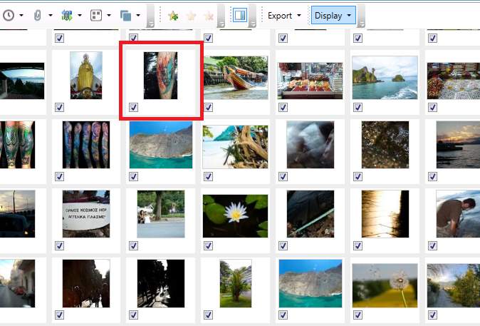
Figure 4 Deleted image, Watercolor Lion.jpg thumbnail
Figure 5 Deleted Images tab UFED Touch
4.2 Cellebrite UFED Touch and dd Physical memory dump Comparison
For this part, a memory dump obtained with UFED Touch was compared with a one taken from custom recovery with the “dd” command, information about the process of physical acquisition through recovery mode with the “dd” command can be found in the Appendix III. Firstly, the memory dump with “dd” command was taken and then with UFED Touch. This order was chosen to minimize the use of the device between the acquisition as well as to minimize the possibilities of files changing. In order for UFED to be able to perform physical acquisition, it loads its own bootloader, which means it would be necessary after the acquisition to re-flash the custom recovery on the device resulting to lot of changes on the device.
For the comparison two different tests were held, the first one was a comparison of the hash values of each partition and the second one a comparison of the forensic analysis of the given memory dumps with UFED Touch software “Physical Analyzer”.
For the first test, the memory dump from UFED Touch was extracted and the files were loaded into “HashMyFiles v2.21” to calculate the hash values. When finished, the same process was followed for the memory dump from the “dd” command. In Figure 6 the “MD5” hash values for the partitions from both acquisitions can be seen with red being the partitions that are not identical. The comparison of the hash values showed that most partitions were the same, as it was expected. The recovery partition it was expected to be different as UFED loads its own bootloader, but as long as there is no full knowledge of what UFED changes exactly on the device it is hard to comment whether or not the changes on these partitions are justified. The only partition that was not expected to be different is the “userdata”, thus a more detailed examination is needed.
Figure 6 Parititons hash values from UFED and dd memory dump.
For further investigation regarding the changes on “userdata” partition “FTK Imager” and a python script were used; the code of the script can be seen in the Appendix I. FTK Imager, has one option that exports a list of all files with hash values and some other information, so the first step was to load both “userdata” files into FTK Imager and get these lists. Once the lists were exported and formatted appropriately in a text file with the following structure “MD5, SHA1, File Path”, then were moved to the script’s folder and the script was executed showing the files that are different.
The steps which the script does in order to achieve that are the following:
- Reads both text files and created dictionary of dictionaries for each file, one dictionary is for “userdata” partition from UFED and the other from “dd” command
- Checks if values on UFED dictionary values exists on “dd” dictionary
- Checks if values on “dd” dictionary exists on UFED dictionary
- Shows the files that each dictionary has but not the other
Both dictionaries should be looped in order to have all the different files. The “key” for the dictionaries is the “MD5” value. The result of this comparison can be seen in Figure 7 and the code on the appendix I. The results in Figure 7 shows that the differences on “userdata” partition were made because of the unallocated space and changes on “File System” files such as “inode table” and “superblock”.
After having shown that user’s data were not altered even if the hash values of “userdata“ partiton do not match, for the second test both files were loaded into “Cellebrite Physical Analyzer” for a forensics analysis. As it can be seen in Figure 8 and Figure 9, both partitions returned the same evidences. These two tests verified that physical acquisition with different techniques are equivalent in terms of recovered evidences but that also the integrity of user’s data is maintained, thus no matter which physical acquisition method will be used the results will be the same and admissible in a court.
Figure 7 Hash file comparion between UFED and dd userdata partition.

Figure 8 UFED analyis of the dd memory dump
Figure 9 UFED analysis of the UFED physical acquisition
4.3 Encrypted device
For this test, the same as before was used but now was fully-encrypted with password “ttu123”. When the encryption was done, the device was booted into recovery mode and a full disk image was taken with “dd” command, the commands can be seen in Figure 10.
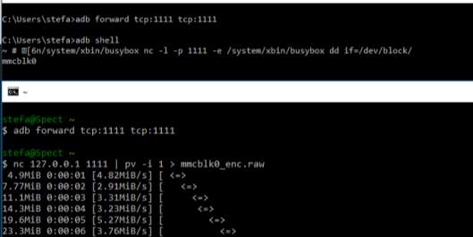
Figure 10 Full memory dump of encrypted Samsung Galaxy S4 using dd comman.
As in the previous test, the memory dump was loaded to “Cellebrite Physical Analyzer” for a forensic analysis. The analysis, Figure 12, returned almost nothing, the images that were found were images that are stored in “aboot” partition Figure 11, and they needed to be unencrypted as they are used before the device is booted and decrypted.
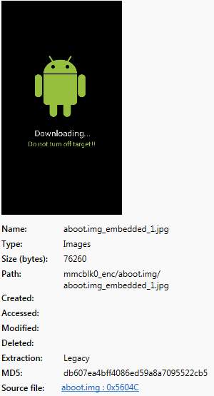
Figure 11 Unencrypted image from encrypted partition analysis
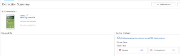
Figure 12 Extraction summary of encrypted memory dump
Furthermore, the encrypted memory dump was loaded into FTK Imager for a quick look into userdata partition. Comparing to a similar non-encrypted memory dump it is easily seen that in the case of an encrypted partition even the file system cannot be identified, Figure 14 shows how an encrypted and unencrypted partition looks like. In order to verify that no information of files, such as file names, cannot be found, a known file on the device was searched, as Figure 13 shows, in the encrypted dump the search did not find a match while in the unencrypted one indicators of the file was found, the specific file “liza.jpg”, was deleted from the device before the acquisition.
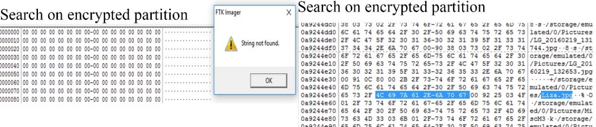
Figure 13 Search for file on encrypted and unencrypted userdata partition
Figure 14 FTK Imager Encrypted and Unencrypted userdata partition
At the moment of this writing, Samsung’s encryption for Android versions 4.0.3 to 4.2.2 has been cracked [21], Samsung is using its own encryption. For Android versions 5.0 and later the full disk encryption has been cracked but the vulnerabilities used, have been patched, some devices may be still vulnerable if the user has not updated the software. More information regarding the encryption cracking can be found here and here.
To sum up, if the device is encrypted, physical acquisition will produce an encrypted memory dump which will be forensically worthless as no information can be found. Under special circumstances, concerning old Android or outdated devices there is a chance for a decryption. It should be noted that companies that provide services for encrypted devices may exist but is not in this scope of this thesis.
4.4 eMMC Test Point Identification
This paragraph is focusing on the identification of the TAPs for the eMMC chip on Nokia Lumia 635 that allows the examiner to perform ISP acquisition. The ISP technique communicates directly with the memory chip without any interference from the CPU as happening in JTAG. This method can be used for other devices as the process is the same. For this process, the following tools are needed:
- ATF flash box
- ATF software
- ATF-V2 4in1 Adapter or ATF-V3 All-in-1 Ultimate Adapter[13] or ATF EMMC Test Point Finder[14]
- 2 cables to provide power to the device and 1 as test point finder probe
- Soldering Iron
- Soldering Wire 0.04mm or 0.02mm.
- Digital Microscope
- Multimeter
- DC Power supplier (not mandatory)
In this thesis, the following tools were used:
- ATF Lightning
- ATF software V12.67
- ATF-V2 4in1 Adapter
- Soldering iron
- Soldering wire 0.02mm
- 2x 1 pin female to crocodile clip wire
- 1x 1 pin female to male jumper wire
4.4.1 ATF 4in1 Adapter setup
The first step is to prepare the adapter, the following cables were used, Figure 15:
- 2x 1 pin female to crocodile clip wire to provide power from adapter to the device
- 1x 1 pin female to male jumper wire for testing purposes. The thinner the tip of the probing cable the better as in some cases the connections are tiny and close to each other.
The female side of the red cable should connect on the voltage while the female side of the black cable should connect on the ground; the colors of the cables do not matter. The third cable should connect on the “green” pin on the ATF Adapter, which is the pin used for probing Figure 16. Instead of using 1 pin female connections on the ATF adapter the cable can be soldered directly on the adapter. The cables used on this test are just a recommendation, a cable with thinner tip for probing would be better.
Figure 15 2x 1pin female to crocodile clip and 1x 1pin female to male jumper wire
Figure 16 ATF-V2 4in1 Adapter
4.4.2 ATF software setup
Latest version of ATF supports CPUs from Qualcomm, Exynos Marvell PXA, Broadcom and Spreadtrum. The following steps will show how to prepare the software for TP identification.
Step 1
Connect ATF 4in1 adapter on ATF flash box, the ATF flash box on USB2.0 port on the computer and run ATF software.
Step 2
From the tab “Nokia Service” Select “ATF Plus” as phone generation and then on tab “Find eMMC TP”.
Step 3
Setup eMMC Test Point Finder. Figure 17 shows the settings used for Nokia Lumia 635.
- CPU Type: The type of CPU that the device has.
- Target: The testing points trying to identify. Always start with CLK and CMD, then VCC if needed and lastly data.
- VCCIO: The voltage to supply the device with. Qualcomm based devices do not need this as a USB cable will be used for power supply. Spreadtrum based devices needs 3.3V.
- Repeat: This sets how many times the program will loop the test. Always set to a big number.
- Delay: Time in seconds between TP identification tries. This gives the necessary time to move the testing probe to another testing point.
Figure 17 ATF software setup for eMMC Test Point Identificaiton
Step 4
Click on “Find eMMC Test Point” and start looking for the test points.
4.4.3 Test Points Identification
Before start looking for TAPs the cables (red and black mentioned in paragraph 4.4.1) should connect on the device, external power from a DC power supply can be used as well. The crocodile clip of the red cable should connect on the (+) positive battery terminal on the device and the black one on the (-) negative one. By placing the battery as it would be when the phone is assembled, the examiner can find out which is the (+) and (-) battery terminals on the device. Experience has shown that usually the first pin is the (+) and the third one is the (-), but always confirm it before connecting the cables. For Nokia Lumia 635 the first pin is (+) and the second is (-). Finally, adapter and device connection should look like in Figure 18.
Before starting the process few very important notes should be mentioned:
- The power button should be pressed during the whole process otherwise it will not work. Two of the easiest ways to do this is by using zip tie or a crocodile clip; holding it by hand is an option but sometimes this is not very convenient.
- Keeping in mind that capacitors are brown and resistors are black can be very useful and speed up the process as test points can be found either in capacitors only or in resistors only.
- CLK and CMD can be found only on resistors
- VCC can be bound only on capacitors
- Data can be found only on resistors
- Not all devices have CMD and CLK test points visible; this means that the PCB should be scratched to reveal the test point.
- VccQ is always on the opposite side of the CMD. More locations can be found with a multimeter.
- For VCC, another cable connected to a power supply with 3.3V must be used.
- Wire length should be as small as possible with 15cm maximum length.
- The order to look for the test points are:
- CMD
- CLK
- VCC (Qualcomm based devices do not need this)
- Data
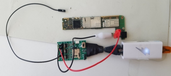
Figure 18 ATF-V2 4in1 Adapter
Now that everything is set up, it is time to start looking for the test points. The process continues after the Step 4 from paragraph 4.4.2. Always start looking around the area of the eMMC. ATF software has instructions on the “Online Tutorial Links” box.
Step 1
Place the tip of the test point probe wire on the resistor and wait for ATF software feedback. If the test point is not correct, it will say to try another location and it will pause for two seconds (delay). It is recommended to try the same test point more than one time. If the test point is correct, a message that says that CMD test point was found will be shown on the screen and a sound will play, Figure 19. Now, solder a wire to the CMD test point on the PCB and to the blue connection on ATF adapter to continue for CLK. You cannot proceed to the next test point if the previous have not been soldered.
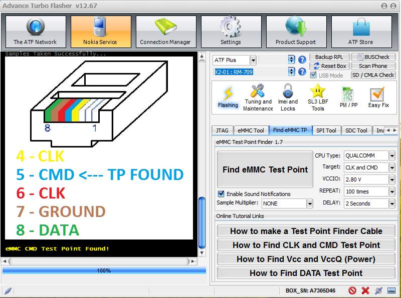
Figure 19 Nokia Lumia 635 CMD TP
Step 2 (Optional)
As was previously mentioned, VccQ is always on the opposite side of the CMD. If it is not very convenient to solder this TP, another place can be found with the “continuity” option on a multimeter. Simply, put one probe on the known VccQ and with the other one start probing other resistors until you hear a “beep” sound. VccQ usually operates with 1.8V but in order to find the exact voltage a multimeter can be used, simply place the positive probe on the VccQ and the negative probe on a ground on the PCB, connect a USB cable and check the value on multimeter’s screen. For Qualcomm based devices this step should be skipped as they get power from a USB cable.
Step 3
Once the CMD is connected properly click again “Find eMMC Test Point” to start looking for the CLK. As before, look only on resistors. When the correct CLK test point has been found, the program will show it on screen and the sound will play, Figure 20. Connect the wire to the corresponding point and continue to step 3. If both red and yellow are on the same test point, the program will show it as in Figure 20. In such cases, it is recommended to solder on wire on the resistor and later split it in two different to connect them on ATF adapter. If only one has been found, solder this wire to the corresponding colour on ATF adaptor and repeat step 3 for the other one. Figure 21 shows a close up of the cables connected on the corresponding access points on the PCB while Figure 22 shows the connections at that point, as said in cases of two access points in one it’s better to solder one cable and split it in two.
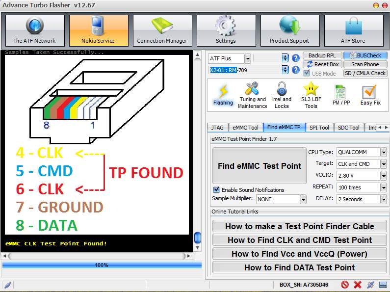
Figure 20 Nokia Lumia 635 CLK TP
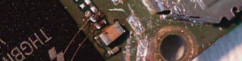
Figure 21 CMD (blue) and CLK (yellod and red) wires soldered close up.
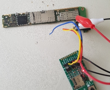
Figure 22 CMD (blue) and CLK (yellod and red) wires soldered.
Step 4 (Ground)
In order to find ground points a multitester is needed: first supply the device with power by using the battery, a usb cable or an external DC power supplier. Then, on multimeter set the knob on “DC”, if is not automatic check the 20V range, touch negative probe on battery terminal and with the other start probing test point on PCB, if the screen shows voltage value (for example 1.8V or 2.8) it means it is not a ground, if screen shows 0 or very close to it (0.01mV) that means that you have found a ground. Connect this point to the ground on the ATF adapter.
Step 5 (Skip in Qualcomm based devices)
For devices such as Samsung and HTC that VCC is needed, to find the VCC test point firstly change the target from “CLK and CMD” to VCC and click on “Find eMMC Test Point” to start the loop again. Take another probe wire which is connected on a DC power adapter with 3.3V and start probing capacitors, when the probe is connected to the correct VCC ATF software will show it on the screen with the same sound as before. VCC is usually 2.8 or 3.3, again as with VccQ the same process with the multimeter can be used to measure the exact voltage. For Qualcomm based devices this step should be skipped as well.
Step 6
Last step is to find the DATA test point, as before every test point found until now should be connected. DATA as CLK and CMD test points can be found only on resistors. When the test point for DATA has been found, the program will display it on screen and will play the sound as well. Connect this last cable on the device and the device will be ready to read (ISP acquisition) or write the eMMC chip. Apart from the message that DATA test point has been found, Figure 23, ATF software will show information about the eMMC chip as well, Figure 24.
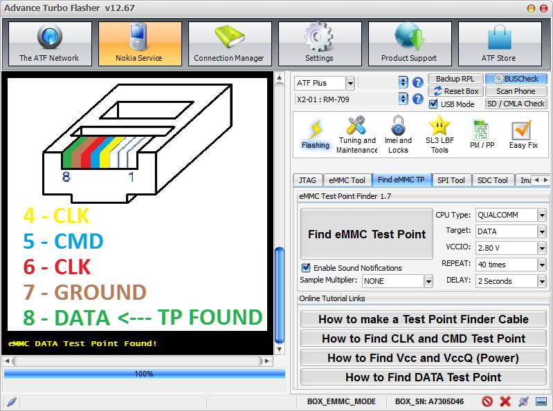
Figure 23 Nokia Lumia 635 DATA TP
The information contains details about the eMMC device such as manufacturer, type, product name and Serial number, for the eMMC boot information such as partition access, boot partition size and user area size which is important for the acquisition later and lastly, it contains information on the card such as version, read and write block length.
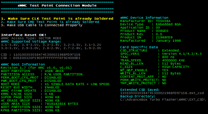
Figure 24 Nokia Lumia 635 eMMC information
An advice not only for this process but for others too, is to invest in tools and time. Tools such as a good microscope, thin probing wire and thin soldering iron will help on making the process of testing and soldering easier, experience will help to do it by finishing this process without damaging the device. Figure 25 shows the TAPs found for this device.
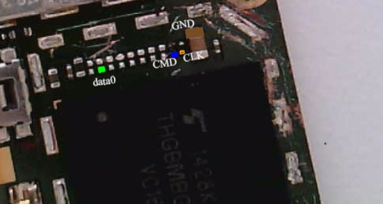
Figure 25 Nokia Lumia 635 Test Access Points for eMMC-ISP acquisition
4.5 ISP Acquisition
This paragraph can be seen as continuation of the previous one. When the examiner knows the test points and everything is connected, the acquisition process can start. For some devices for the connection a jig can be used; jigs are small PCBs which allows to connect to the device’s eMMC TAPs without soldering anything. Each jig is made for one device only, as different devices have different location for the test points, and not all devices have jigs. The process of the acquisition is very easy and straightforward as long as the soldering was done correctly.
Step 1
Select “eMMC Tool” tab under Nokia Service – ATF Plus on ATF software.
Step 2
Select the CPU type, for this test the “Nokia Lumia – Snapdragon 2,3,4” was selected and click “Scan eMMC”. If the connections are solid and connection with the eMMC chip is established, the same information as in Figure 24 will be shown on the screen, from “eMMC Boot Information” write down the “user area size” for the next step.
Step 3
Select partition to dump as well as the size of this partition. The user area written down on step 2 was 7818182656 bytes which corresponds to 8GB storage. Select 8GB for “Size” and the program will automatically fill the “End Block” by itself, Figure 27.
Step 4
Set up the VCCIO, set up the value found for the VccQ. If it’s not known, start from 1.8V and move to 3.3V if necessary. For this device, it was irrelevant as the device was powered up from a USB cable.
Step 5
Set eMMC clock speed 15 MHz; if it does not work, try other values. A look on the chip’s datasheet can give information about clock speed but it is easier to try different values.
Step 6
Click “READ”, give a name for the memory dump output and wait. The program will show on screen which partition was selected for reading, the remaining sectors and time left to finish the acquisition, Figure 27.
On the bottom right side on the big red box on left side in Figure 27 it shows the number of “Retries”; this numbers represents how many times the ATF box lost communication with the eMMC chip. Poor connection is indication of bad soldering; thus, the wires should be re-soldered carefully. Also, poor connections have a result of slower acquisition and in some cases, it may be unable to finish.
The tools used in this thesis were not adequate (thick soldering tip and no microscope) for this task, which resulted in poor connection. At 49% of the acquisition the connection was lost until the program froze and the acquisition stopped completely; 4GB of the memory was copied by that time. After lots of unsuccessful attempts to solder the wires again, it was not possible. Nevertheless, the memory dump was enough to load in UFED for analysis as Figure 26 shows. This device was bought for testing purposes for a real case and it was completely empty from files and user’s activity. Even though the device was empty and the memory dump was only half of the actual memory, it was enough to show the process of an ISP acquisition and to return evidences when analyzed with a forensic tool.
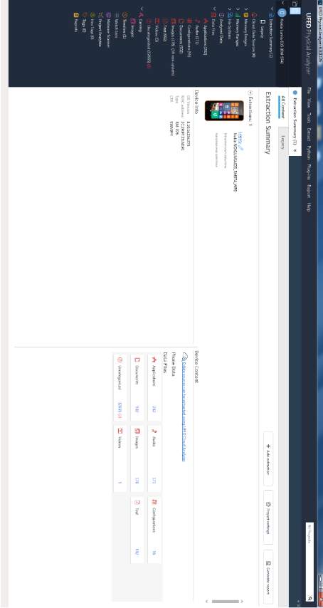
Figure 26 Nokia Lumia 635 ISP memory dump analysis with UFED Physical Analyzer
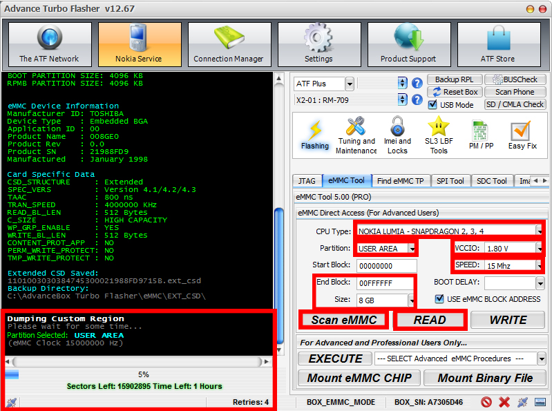
Figure 27 ISP Acquisition settings
4.6 JTAG Acquisition
JTAG acquisition is similar to ISP but it uses different test points. For the JTAG acquisition, Samsung Galaxy S4 I9505 was used. For JTAG acquisition the following tools needed:
- Flash box that supports JTAG read option. Riff box is a well-known flash box for JTAG. ATF’s box JTAG module has only repair function and not ready.
- Flash box software
- Soldering iron
- Soldering wire 0.04mm or 0.02mm
- Digital microscope
- DC power supply (not mandatory but useful)
In this test, the following tools were used:
- Riff Box
- JTAG Manager for Riff box v1.65
- Soldering iron
- Soldering wire 0.02mm
- JTAG Jig for Samsung Galaxy S4 I9505
4.6.1 JTAG Test Access Points
For this part it is assumed that the JTAG pinout interface is already known, the sources to look for JTAG pinout as mentioned in paragraph 2.3.2.1 are flash box’s software, Google, forums, manually by probing the tips and from device’s schematics. JTAG jigs exists for some phones such as the one used for this test. This jig allows to connect the device with the flash box for JTAG acquisition without soldering any wires. Jig should be purchased separately but the cable to connect the jig with the flash box comes with the flash box. If the device is not supported but the JTAG interface pinout is known, similar phone’s (CPU), settings can be tried. Always, a task that is not verified should be tested firstly in another device identical to the original one. To find the supported devices from Riff box and the JTAG interface pinout follow the steps:
Step 1
From “Box service” select “Check for Updates”.
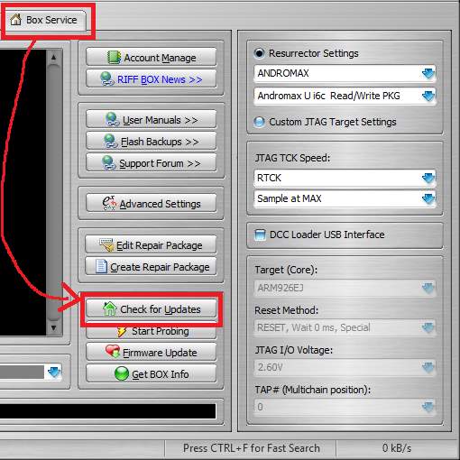
Figure 28 Riff Box “Check for Updates”
Step 2
On the “Riff Updates Manager” pop up window select “Resurrectors” under “JTAG Manager Root”. Select manufacturer and look for the device. When the device is located download the file. When the download is finished, Riff box will install the files and software will restart.
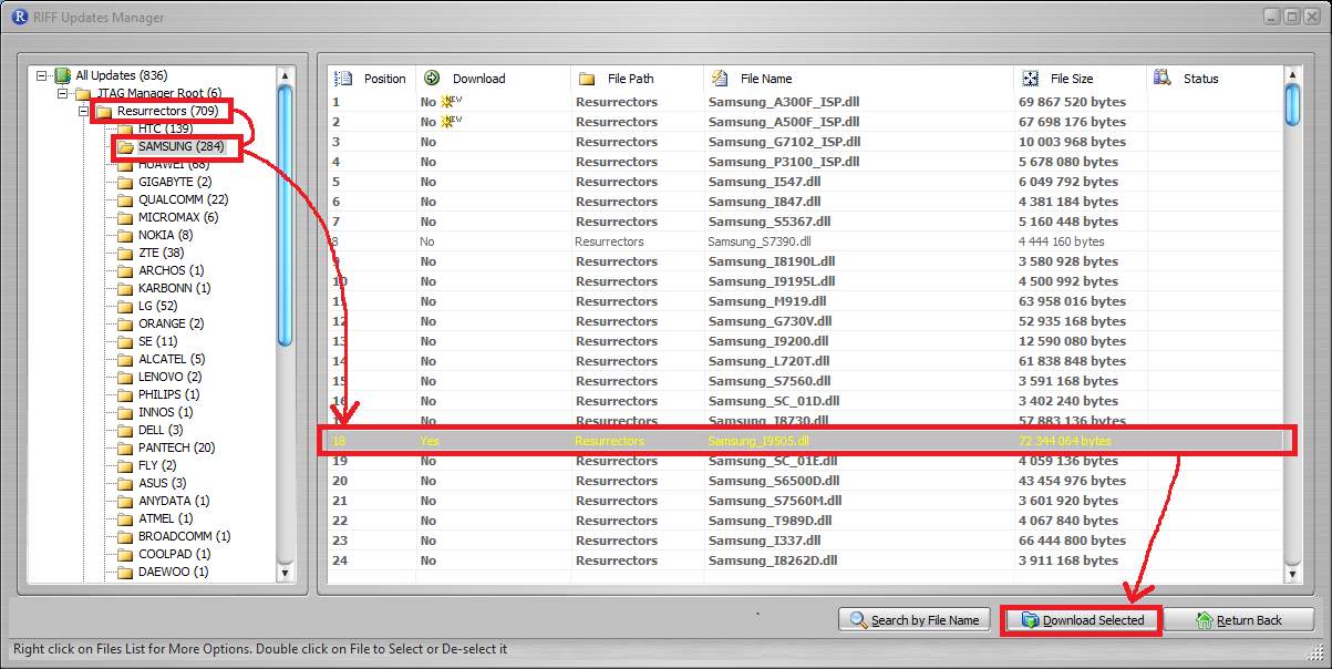
Figure 29 Downloading device’s necessary files for JTAG
Step 3
Under “Resurrection” tab select “Interface Pinout” to see the JTAG pinout for this device. This option is not available for all devices. In that case, examiner should find JTAG pinout by himself. Figure 30 shows the pinout interface for the device used in this thesis.
Step 4
Solder the wire on phone’s PCB according to Figure 30 or use a jig if available and connect it with Riff box. Figure 31 a shows how the cable for soldering on JTAG interface looks like and Figure 31 b shows the cable with a JTAG jig.
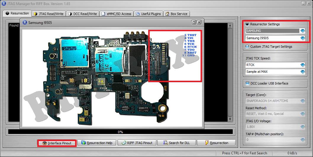
Figure 30 Resurrector Settings and JTAG Interface Pinout
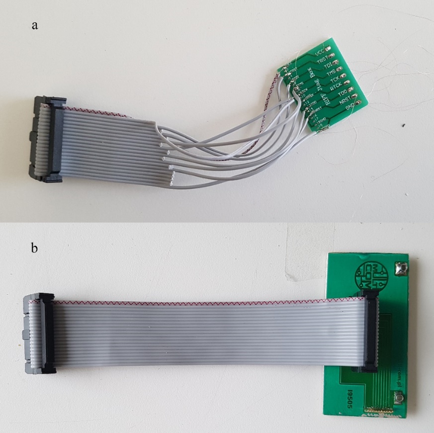
Figure 31 Riff Box JTAG connection a) soldering b) jig
4.6.2 JTAG Acquisition Process
When the device is connected with the Riff box, it is time for the acquisition and as with ISP the process is relatively simple.
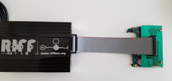
Figure 32 Samsung Galaxy S4 I9505 connected to Riff Box via jig
Step 1
Open “JTAG Read/Write” tab.
Step 2
On “Ressurector Settings” select device manufacturer and model. This option will show only the models you have downloaded before, as explained in the previous paragraph. If the device is not supported, proceed on Step 3 otherwise on Step 4.
Step 3
In case of a device not supported from Riff box, select “Custom JTAG Target Settings”.
- “JTAG TCK Speed” start with maximum and start lowering every time.
- “Target Core” select device’s CPU; if not supported, select a similar one if possible. Any unverified test should be done firstly in another device identical to the original.
- JTAG I/O start with 1.8V and change to higher values if necessary.
Step 4
At the beginning, only the last four options are clickable. Click “Connect & Get ID”, if the connection is established, a message that a “dead body” was detected will be shown and all options will be now clickable, Figure 33.
Step 5
Click “Read Memory” and wait until the program has finished. It may need to try few times until it works, Figure 33.
Step 6
Analyze the memory dump with any forensic tool.
For this process, a DC power supply was used and during the setup due to a misconfiguration or hardware fault the power supplier provided a huge amount of current which damaged the device in an unrecoverable way, at least with current tools and time. Due to this event, it was not possible to perform a JTAG acquisition. This unfortunate event can be a reminder on how careful an examiner should be when he is working with original devices in real cases.
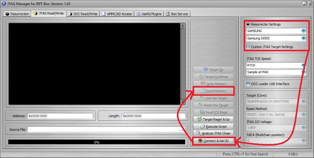
Figure 33 Riff Box JTAG Read/Write Tab
5 Conclusion and Future Work
Nowadays more than 2 billion people own a smartphone and this number is growing rapidly, which makes mobile forensics a very important part of the digital forensic science. The big variety οf manufacturers, devices and the state a device can be can make the data acquisition a very easy or very difficult task. The data acquisition can be categorized in logical, file system and physical and each category can have more than one techniques applicable. Some of the data acquisitions are as easy as connecting the device on a specific device e.g. Cellebrite UFED Touch logical acquisition, while some others are more advanced, with a risk of damaging the device e.g. JTAG and ISP acquisition.
This study focused mostly on giving an overview of the JTAG and ISP acquisition but also some information regarding the different types of acquisitions as well as cases of encrypted device.
To begin with the types of acquisition, this study showed that in terms of evidences regarding the usage of a device all three acquisitions are equivalent, but when it comes to actual files such as images, videos and documents the physical acquisition gives the most information of them all. Thus, it is recommended to start with the logical acquisition and only if necessary to perform a file system or physical acquisition.
There are few different ways that an examiner can perform a physical acquisition with two emerging techniques being JTAG and ISP. The main goal of this study was to provide some information about these techniques. As this study showed, both techniques are not easy and the device can be easily damaged. Special tools, hardware and software needed, and the connection process (between device and computer through a flash box) can be very difficult. Once the difficult part of the connection has been made, the read process is very easy and the dump taken is equivalent to any other physical acquisition technique and can be used for forensic analysis.
One of the main problems of these two acquisition techniques, is the access points in which you have to connect the device. In cases in which these points are not known, a manual identification can be performed. In this study, only the process to identify the access points for an ISP acquisition was tested. The process is relatively simple but there can be cases in which this process can be difficult such as when a test point is hidden and the surface of the PCB has to be scratched; in these cases, experience will make all the difference.
Finally, one of the tests was performed on an encrypted device, which resulted in zero evidences. This test put a question mark on the future of the mobile forensics as all smartphones start having encryption enabled by default.
As technology is moving forward very fast, many researches are already obsolete and further tests will always be needed. The two main tests that have to be done that are related to this thesis are chip-off acquisition techniques and creating a clone of the original device with JTAG, ISP or chip-off acquisition. For the chip-off acquisition most people think about expensive adapters in which the eMMC chip is mounted, but ISP acquisition can be performed by connecting directly on the chip instead of a PCB. There are many cases in which the evidences to catch a suspect can be found by using the device pretending to be the owner and communication with someone else who may be a suspect. Looking for such evidences can be resulting to the alteration or deletion of other evidences. Thus, what is proposed as future work is to obtain a full memory dump using JTAG, ISP or chip-off acquisition from the original device and then again with one of these techniques write the memory dump to the clone device (should be the exact same as the original) and use the clone device as if it was the original one. In that way, the extra evidences would have been found and the original device will remain intact.
To sum all up, simpler and less risky data acquisition should be tried first and move on to more advanced methods only if the previous ones were not adequate. JTAG and ISP acquisition should be performed from experienced examiners that should always be very careful. For most acquisitions Cellebrite UFED Touch 2 (newest version of Cellebrite UFED Touch) is the best option, for JTAG and ISP the following tools are the most appropriate:
- Riff Box with its software (JTAG)
- Advanced Turbo Flasher with its software (ISP)
- Soldering iron with thin tip
- Bridging wire 0.02mm
- A good microscope at least 10x
- External DC power supply
- VR Table for eMMC and JTAG (not mandatory but very useful, and expensive, as you do not need to solder wires)
Finally, If the device is encrypted, then there are not many things that an examiner can do, so alternatives should be considered.
6 References
| [1] | “Smartphone users worldwide 2014-2020,” June 2016. [Online]. Available: https://www.statista.com/statistics/330695/number-of-smartphone-users-worldwide/. [Accessed 22 01 2017]. |
| [2] | “Mobile device forensics,” [Online]. Available: https://en.wikipedia.org/wiki/Mobile_device_forensics. [Accessed 22 01 2017]. |
| [3] | “IDC: Smartphone OS Market Share, 2016,” 11 2016. [Online]. Available: http://www.idc.com/promo/smartphone-market-share/os;jsessionid=9331D99BA89FE54BBA1A553649669DF7. [Accessed 22 01 2017]. |
| [4] | A. Hoog, Android Forensics: Investigation, Analysis and Mobile Security for Google Android, 1 ed., Syngress, 2011. |
| [5] | “Digital forensics,” [Online]. Available: https://en.wikipedia.org/wiki/Digital_forensics. [Accessed 30 01 2017]. |
| [6] | “Digital Forensic Process,” [Online]. Available: https://en.wikipedia.org/wiki/Digital_forensic_process. [Accessed 30 01 2017]. |
| [7] | SWGDE, SWGDE Best Practices for Mobile Phone Forensics, 2.0 ed., 2013. |
| [8] | “Cellebrite – Explaining Cellebrite UFED Data Extraction Processes,” [Online]. Available: http://www.cellebrite.com/pages/explaining-cellebrite-ufed-data-extraction-processes. [Accessed 23 02 2017]. |
| [9] | “Android Debug Bridge | Android Studio,” [Online]. Available: https://developer.android.com/studio/command-line/adb.html. [Accessed 30 01 2017]. |
| [10] | D. Stieben, “What Is A Nandroid Backup and How Exactly Does It Work?,” 11 01 2014. [Online]. Available: http://www.makeuseof.com/tag/what-is-a-nandroid-backup-and-how-exactly-does-it-work/. [Accessed 31 01 2017]. |
| [11] | J. T. A. G. (JTAG), “IEEE Standard 1149.1 (JTAG) in the SX/RTSX/SXA/eX/RT54SX-S”. Patent 1149.1, 05 2012. |
| [12] | “JTAG, Chip-off & ISP Training and Equipment Guide,” [Online]. Available: http://www.teeltech.com/mobile-device-forensics-training/equipment-guide/. [Accessed 26 01 2017]. |
| [13] | J. Reyes-Rodriguez , JTAG Tool Testing, 2016. |
| [14] | SWGDE, Best Practices for Examining Mobile Phones Using JTAG, 1.0 ed., 2015. |
| [15] | T. Kingston, “Embedded Multi-Media Card Specification (e•MMC™4.5)”. 2013. |
| [16] | J. Swauger, “Chip-Off Forensics,” Extracting a full bit-stream image from devices containing embedded flash memory, pp. 52-56, 2012. |
| [17] | D. Tindall and R. Tamma, Learning Android Forensics, 2015. |
| [18] | V. Djagilev, “Android Chat Application Forensic Process Improvement & XRY Support,” Tartu University, Tallinn, 2017. |
| [19] | J. Lessard and G. C. Kessler, “Android Forensics: Simplifying Cell Phone Examinations,” Small Scale Digital Device Forensics Journal, vol. 4, 09 2010. |
| [20] | N. Son, Y. Lee, K. Dohyun, J. I. James, S. Lee and K. Lee, “A Study of User Data Integrity During Acquisition of Android Devices,” in The Digital Forensic Research Conference, Monterey, CA, 2013. |
| [21] | “How To Decrypt Android Full Disk Encryption,” 01 10 2014. [Online]. Available: http://forensicswiki.org/wiki/How_To_Decrypt_Android_Full_Disk_Encryption. [Accessed 07 03 2017]. |
Appendix
Hash Comparison Python Script
ufed = “ufed.txt”
ufed_dic = {}
dd = “dd.txt”
dd_dic = {}
sum = 0
#Open ufed userdata image file hash list
#And creates a dictionary with main key the MD5 value
with open(ufed) as f:
for line in f:
md5 = line.split(“,”)[0]
sha1 = line.split(“,”)[1]
file_name = line.split(“,”)[2]
ufed_dic[md5] = {‘sha1’: sha1, ‘file_name’: file_name}
#Open dd userdata image file hash list
#And creates a dictionary with main key the MD5 value
with open(dd) as f:
for line in f:
md5 = line.split(“,”)[0]
sha1 = line.split(“,”)[1]
file_name = line.split(“,”)[2]
dd_dic[md5] = {‘sha1’: sha1, ‘file_name’: file_name}
#Checks which files from ufed hash list they do not exist
#on dd hash list based on the MD5 value
for md5_dd_to_check in ufed_dic:
if md5_dd_to_check in dd_dic:
sum += 1
else:
print(ufed_dic[md5_dd_to_check])
print(sum)
#Checks which files from dd hash list they do not exist
#on ufed hash list based on the MD5 value
sum = 0
for md5_dd_to_check in dd_dic:
if md5_dd_to_check in ufed_dic:
sum += 1
else:
print(dd_dic[md5_dd_to_check])
print(sum)
- Media Files and Application Setup
Media files [15]
| Camera20170207_111614.jpg |
| Camera20170207_111632.jpg |
| Camera20170207_111641.jpg |
| DocumentsICMP covert.pdf |
| DocumentsSWGDE_Best_Practices_for_Examining_Mobile_Phones_Using_JTAG.pdf |
| DocumentsSWGDE_Best_Practices_for_Mobile_Phone_Forensics.pdf |
| DocumentsSWGDE_Core_Competencies_for_Mobile_Phone_Forensics.pdf |
| DownloadBest Practices for Incident Responders Collecting Electronic Evidence.pdf |
| DownloadNIST.SP.800-101r1.pdf |
| DownloadSWGDE_Best_Practices_for_Chip-Off.pdf |
| DownloadSWGDE_Best_Practices_for_Collection_of_Damaged_Mobile_Devices.pdf |
| Pictures20160811_140758.jpg |
| Pictures20160821_183231.jpg |
| Pictures20161023_114837.jpg |
| PicturesAmpelakia_0007.JPG |
| PicturesAmpelakia_0031.JPG |
| PicturesDSC_002.JPG |
| PicturesDSC_0195.jpg |
| PicturesDSC_0255.JPG |
| PicturesDSC_027.JPG |
| PicturesDSC_031.jpg |
| PicturesDSC_0326.jpg |
| PicturesDSC_0429.jpg |
| PicturesDSC_0477.jpg |
| PicturesDSC_0662.jpg |
| PicturesDSC_068.jpg |
| PicturesDSC_069.jpg |
| PicturesDSC_071.jpg |
| PicturesDSC_122.JPG |
| PicturesDSC_156.jpg |
| PicturesDSC_174.jpg |
| PicturesDSC_175.jpg |
| PicturesDSC_195.jpg |
| PicturesDSC_298.jpg |
| PicturesDSC_300.jpg |
| PicturesDSC_445.jpg |
| PicturesDSC_7960.jpg |
| PicturesDSC_7993.jpg |
| PicturesDSC_8086.jpg |
| PicturesFortress.jpg |
| PicturesG0013126.JPG |
| PicturesG0177901.jpg |
| PicturesGOPR1405.jpg |
| PicturesGOPR2873.jpg |
| Picturesgreen owl.jpg |
| PicturesGr_Cf (1).JPG |
| PicturesGr_Cf (11).JPG |
| PicturesGr_Cf (12).JPG |
| PicturesGr_Cf (13).JPG |
| PicturesGr_Cf (14).JPG |
| PicturesGr_Cf (16).JPG |
| PicturesGr_Cf (17).JPG |
| PicturesGr_Cf (18).JPG |
| PicturesGr_Cf (19).JPG |
| PicturesGr_Cf (2).JPG |
| PicturesGr_Cf (21).JPG |
| PicturesGr_Cf (22).JPG |
| PicturesGr_Cf (23).JPG |
| PicturesGr_Cf (24).JPG |
| PicturesGr_Cf (26).JPG |
| PicturesGr_Cf (27).JPG |
| PicturesGr_Cf (28).JPG |
| PicturesGr_Cf (29).JPG |
| PicturesGr_Cf (3).JPG |
| PicturesGr_Cf (31).JPG |
| PicturesGr_Cf (32).JPG |
| PicturesGr_Cf (33).JPG |
| PicturesGr_Cf (34).JPG |
| PicturesGr_Cf (36).JPG |
| PicturesGr_Cf (37).JPG |
| PicturesGr_Cf (38).jpg |
| PicturesGr_Cf (39).jpg |
| PicturesGr_Cf (4).JPG |
| PicturesGr_Cf (41).JPG |
| PicturesGr_Cf (42).JPG |
| PicturesGr_Cf (43).JPG |
| PicturesGr_Cf (44).JPG |
| PicturesGr_Cf (46).JPG |
| PicturesGr_Cf (47).jpg |
| PicturesGr_Cf (48).JPG |
| PicturesGr_Cf (49).jpg |
| PicturesGr_Cf (51).JPG |
| PicturesGr_Cf (52).JPG |
| PicturesGr_Cf (53).jpg |
| PicturesGr_Cf (54).JPG |
| PicturesGr_Cf (56).JPG |
| PicturesGr_Cf (57).JPG |
| PicturesGr_Cf (58).JPG |
| PicturesGr_Cf (59).JPG |
| PicturesGr_Cf (6).JPG |
| PicturesGr_Cf (61).JPG |
| PicturesGr_Cf (62).JPG |
| PicturesGr_Cf (63).jpg |
| PicturesGr_Cf (64).jpg |
| PicturesGr_Cf (66).JPG |
| PicturesGr_Cf (67).JPG |
| PicturesGr_Cf (68).JPG |
| PicturesGr_Cf (69).jpg |
| PicturesGr_Cf (7).JPG |
| PicturesGr_Cf (71).jpg |
| PicturesGr_Cf (72).jpg |
| PicturesGr_Cf (73).JPG |
| PicturesGr_Cf (74).JPG |
| PicturesGr_Cf (76).JPG |
| PicturesGr_Cf (77).jpg |
| PicturesGr_Cf (78).JPG |
| PicturesGr_Cf (79).jpg |
| PicturesGr_Cf (8).JPG |
| PicturesGr_Cf (81).JPG |
| PicturesGr_Cf (9).JPG |
| PicturesLG_20160219_131716.jpg |
| PicturesLG_20160219_131744.jpg |
| PicturesLG_20160219_132653.jpg |
| PicturesMiscAngry Owl.jpg |
| PicturesMiscDSC_0190.JPG |
| PicturesMiscDSC_0191.JPG |
| PicturesMiscDSC_0328.jpg |
| PicturesMiscDSC_0339.JPG |
| PicturesMiscLanding In Moscow.MP4 |
| PicturesMiscNight TimeLapse.mp4 |
| PicturesMiscPanoramic Balcony.mp4 |
| PicturesNatureAmpelakia_0018.JPG |
| PicturesNatureDSC_0041.JPG |
| PicturesNatureDSC_0367.JPG |
| PicturesNatureDSC_040.jpg |
| PicturesNatureG0057648.jpg |
| PicturesRandomAmpelakia_0061.JPG |
| PicturesRandomColored birds.jpg |
| PicturesRandomDSC_0567.jpg |
| PicturesRandomDSC_362.jpg |
| PicturesRandomGOPR2883.jpg |
| PicturesRandomLG_20160219_131618.jpg |
| Telegram picture423640518_95206.jpg |
| DocumentsRubik’s Cube 3×3 Guide.pdf |
| PicturesLiza.jpg |
| PicturesDSC_197.jpg |
| PicturesDSC_0047.JPG |
| PicturesMiscDSC_229.jpg |
| PicturesMiscGuangzhou 23rd Floor Balcony View.mp4 |
| PicturesNatureDSC_0016.JPG |
| PicturesNatureDSC_0578.jpg |
| PicturesRandomWatercolor Lion.jpg |
| PicturesGr_Cf (5).JPG |
| PicturesGr_Cf (10).JPG |
| PicturesGr_Cf (15).JPG |
| PicturesGr_Cf (20).JPG |
| PicturesGr_Cf (25).JPG |
| PicturesGr_Cf (30).JPG |
| PicturesGr_Cf (35).JPG |
| PicturesGr_Cf (40).JPG |
| PicturesGr_Cf (45).JPG |
| PicturesGr_Cf (50).jpg |
| PicturesGr_Cf (55).JPG |
| PicturesGr_Cf (60).JPG |
| PicturesGr_Cf (65).JPG |
| PicturesGr_Cf (70).JPG |
| PicturesGr_Cf (75).jpg |
| PicturesGr_Cf (80).JPG |
Device
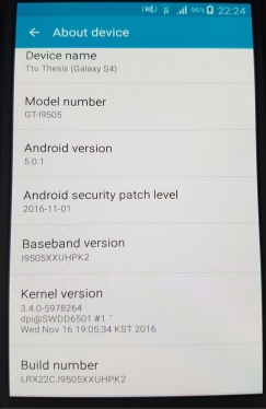
Device Status
- Official ROM
- Rooted with SuperSU Free v.279
- TWRP 2.8.4.0 custom recovery
Google Searches
- ttu
- Forensic
- Samsung S4
- Android
- Samsung S7 Edge
- Ars Technica
Visited URLs
- https://www.ttu.ee/en
- https://en.wikipedia.org/wiki/Forensic_science
- https://en.wikipedia.org/wiki/JTAG
- http://www.gsmarena.com/samsung_i9500_galaxy_s4-5125.php
- http://gadgets.ndtv.com/samsung-galaxy-s4-542
- https://www.android.com/
- https://www.google.com/photos/about/
- http://www.samsung.com/global/galaxy/galaxy-s7/
- www.e-shop.gr
- http://www.crazysundays.gr/
- m.ebay.com/?_mwBanner=1
- https://arstechnica.com/
- https://arstechnica.com/apple/2017/02/testing-out-snapshots-in-apples-next-generation-apfs-file-system/
YouTube
- Nerf War: First Person Shooter 9
- Android Authority
Installed Applications
- TWRP v2.8.4.0
- SuperSU Free v2.79
- BusyBox Free 1.262
- Telegram
Actions
- Email from ttuthesis@gmail.com to thesisttu@gmail.com and vice versa.
- Exchange instant messages with Telegram
- Connect to “LP” Wi-Fi
- Browse the internet with Chrome and watch videos on YouTube
- Cellebrite UFED Touch Logical, File System and Physical Acquisition
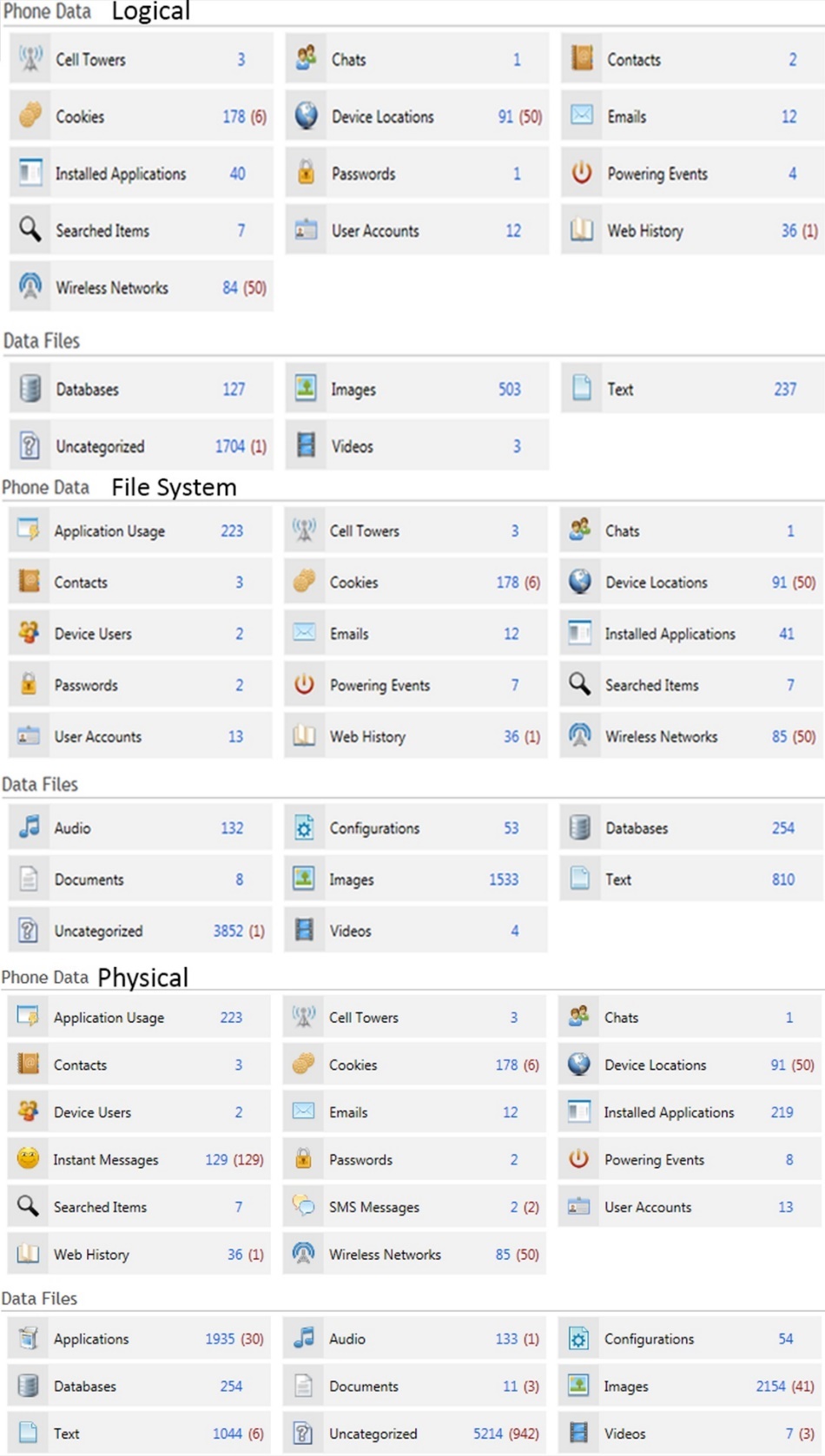
Figure 34 UFED summary extraction of logical,file system and physical acquisition
Physical Acquisition with “dd” command.
In order to use “dd” command on an Android device for full memory dump or just to dump a specific partition the device must be rooted, with custom recovery and BusyBox installed as well. The process to root a device and flash custom recovery is not the same for all devices so this part will be omitted.
From the computer side, all that is needed is “adb” tool and Cygwin for Windows computers. Cygwin provides Windows a variety of open source tools from Linux, the one needed is “netcat” but “pv”, which is useful for checking the progress. The steps are:
- Boot the device into recovery mode and connect it to the computer. Memory dump of some partitions, userdata included, can be obtained even with the device being booted normally, debugging should be enabled.
- Mount the available partitions; system is the important one.
- Open terminal on a computer and verify that the PC can talk to the device with the “adb devices” command. It should return the device’s number and status, in this case recovery.
- Then run “adb forward tcp:1111 tcp:1111” to forward the data on this port. Port number can be anything.
- Then “adb shell” to get access to device’s terminal.
- Once inside the device, look for the name of the block for acquisition. On the paragraph 2.3.2.4 was mentioned how to find the block. The block on Samsung Galaxy S4 GT-I9505 can be seen on the Figure 1. The blocks and the corresponding names can be seen on the Figure 2, this is not available for all devices. For full memory dump choose the main block (mmcblk0).
- Run the command “/system/xbin/busybox nc -l -p 1111 -e /system/xbin/busybox dd if=/dev/block mmcblk0”. This command it reads the block specified and sends the data to the port mentioned.
- Open a second Cygwin terminal this time, run the “adb forward tcp:1111 tcp:1111”, port should be the same with the one on the other terminal.
- Run the command “nc 127.0.0.1 | pv -i 1 > mmcblk0.raw”. This command listens on the loopback address for the data that is being sent from the device and writes it in a file with the name “mmcblk0.raw”. The “pv” command is used to give an update for the process every one second. The process can be seen on the Figure 35; the screenshot was from the encrypted partition thus the name “mmcblk_enc.raw”.

Figure 35 Commands for full memory dump on a Windows computer.
[1] Joint Test Action Group
[2] In-System Programming
[3] Test Access Point
[4] Operating System
[5] Yet Another Flash File System 2
[6] Android Debug Bridge
[7] ClockWorkMod
[8] Team Win Recovery Project
[9] Printed Circuit Board
[10] Advaned Turbo Flasher
[11] Scientific Working Group on Digital Evidence
[12] Small Scale Digital Device Forensics Journal
[13] ATF-V3 All in 1 Adapter comes with test point finder probe wire
[14] ATF eMMC Test point finder comes with all three cables needed
[15] Red cells indicates deleted files.
[16] Contacts are not available in every test.
Cite This Work
To export a reference to this article please select a referencing stye below:
Related Services
View all


Related Content
All TagsContent relating to: "Forensic Science"
Forensic science, or forensics, is the application of science to criminal and civil law, usually during criminal investigation, and involves examining trace material evidence to establish how events occurred. Forensic scientists provide impartial scientific evidence that can be used in court.
Related Articles

DMCA / Removal Request
If you are the original writer of this dissertation and no longer wish to have your work published on the UKDiss.com website then please: