Dimethyl Ether Market Production Technology
Info: 9729 words (39 pages) Dissertation
Published: 9th Dec 2019
Tagged: ChemistryTechnology
Executive Summary
Table of Contents
2.5 Competitors and Market Share
3.4 Final Location of DME production Facility
4.4 CO2 Hydrogenation to Form Methanol
4.5 Methanol Dehydration to Form Dimethyl Ether
5.2 Assumptions and Methodology
5.3 Cost Estimate Classification
1 Introduction
2 Market Analysis for DME
2.1 Historical DME Demand
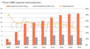
Commercial production of DME initiated in 1963 by Akzo Nobel for use in aerosol propellants as non-ozone depleting substitute to CFCs (McKone, et al., 2015). With increasing oil prices in the 1970s and 1980s due to numerous embargos, global R&D programs were introduced focusing on the use of DME as an alternative fuel. The first fuel DME project was launched in the late 20th century with a joint venture between oil giant Amoco, the India Oil Company and the Gas Authority of India (McKone, et al., 2015). Soon followed the establishment of various fuel DME associations including the International DME association, the Japan DME Forum and the China DME Association. The early to mid-2000s saw the emergence of China as a dominate force in global DME production. The commercialisation of LPG blending promoted a production capacity increase of 467% from 3Mt in 2007 to 14Mt in 2015 (CCF Group, 2016).
2.2 Current Global Demand
Analysis of the global Dimethyl Ether (DME) market revealed the industry to be worth an estimated USD 5.16 billion in 2015, with significant growth recorded over the last decade (Global Market Insights Inc, 2016). The market share is divided amongst three major regions being the Asian pacific, North America and Europe. The Asian Pacific region, mainly led by China dominates the industry with over 95% market share.
To describe the extent of the role China plays in the DME market, in 2012 China was responsible for consuming more than 90% of the world’s DME, while having a 12 million tonne per year production capacity (CCF Group, 2016). Although the Chinese market posted very strong growth in the 2000s, however recent bans being imposed by the government on LPG blending and a shutdown of illegal blending practices have stifled growth. In turn, this has resulted in an overcapacity of DME and an only 20-30% utilisation rate of production facilities.
2.3 Applications
In today’s market, applications of DME can be divided into 4 major categories:
- Aerosol Propellant
- Transportation fuel
- LPG blending
- Industrial fuel and feedstock
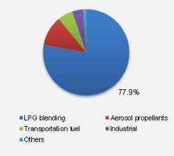
Traditionally, the use of DME in aerosol products including hairsprays and cosmetics has been the most widespread application. However, China who is the world’s largest consumer of LPG have commercialised the use of DME in LPG blending. LPG blending involves the blending of LPG with 20% DME which can be used in domestic households. As of 2013, an estimated 78% of global DME was utilised in LPG blending.
This has greatly benefited China in relying less on LPG imports and also reducing its emission footprint through the introduction a cleaner domestic fuel. Companies in Indonesia, India and Vietnam have expressed desire in implementing LPG blending in their respective countries.
Transportation fuel is a relatively newer DME application venue that is yet to be widely commercialised, however it is believed to be the most promising growth opportunity for the DME market in the future.
DME’s quality ignition and high Cetane number makes it ideal as a low pollutant substitute for diesel fuel in both heavy trucks and passenger vehicles. The benefits of using DME as an alternative to diesel is that existing LPG infrastructure can still be used for the transportation and storage of DME and only minor vehicle modifications will be required.
 This adoption of non-petroleum based fuel alternative has been strongly supported by automotive manufacturers, in particular heavy duty truck companies such as Volvo and Mack. These companies are the first in the world to have a commercial DME fuelled truck fleet that is available in the North American market. Additionally, Ford are leading a EUD 3.5 million research project in the development DME fuelled passenger vehicles in collaboration with the German government.
With the introduction of stringent environmental regulations and the rising awareness of petroleum fuel pollution, it is projected that the DME market will see enormous growth in the transportation fuel sector in the next decade.
2.4 Current Australian Demand
Review of the Australian DME market revealed to be no current DME production facilities operating in Australia (Syed, Nowakowski, Nicholson, & Ahmed, 2014). Even though Australia has Asia’s second largest aerosol products market, DME usage in this industry is relatively small scaled and demand is adequately met by imports from China. Having said that, CSR operated a 10 kt/y DME plant in NSW, Australia in 1988 for aerosol propellant use however this has since been dismantled (Syed, Nowakowski, Nicholson, & Ahmed, 2014).
The major challenge facing Australian DME production is the lack of incentives by investors due to very limited application of DME in the Australian fuel market and high cost of producing renewable DME (Gough, 2016). In 2002, Japanese consortium Japan DME planned to build the world’s largest DME plant in the Burrup Peninsula, Western Australia that was expected to produce approximately 1.65 Mt/a. However the project was abandoned a few years later citing the inability to source natural gas at a reasonable cost. Hence, production cost is a major challenge in the implementation of large scale DME production in Australia.
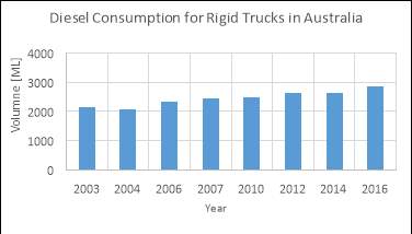
With the small scale use of DME in the aerosol industry and the absence of LPG blending due to Australia’s high LPG capacity, the transportation fuel market is identified as the most attractive option for application in Australia. Australia is one of the world’s largest diesel consumers per capita with over 13.9 billion litres used by the road transportation sector in the 2015/16 financial year. Furthermore, the introduction of DME fuelled heavy duty trucks by Volvo and Mack who own a 25% share of Australia’s heavy duty trucking industry has elevated the prospect of replacing diesel with DME. Therefore, there is a great incentive in the introduction of DME fuelled vehicles in Australia as a lower emission substitute to diesel.
2.5 Competitors and Market Share
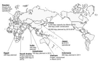
In addition to China, Japan has been recently involved in developing large commercial DME operations such as the Niigata City DME plant which became operational in 2011. Others including Sweden, Iceland, Germany and the US have all invested in small DME production facilities to meet local demands. Although there are only a few countries currently involved in commercial DME production, a very large number are developing plans to build large capacity DME plants. Countries ranging from South Korea, Iran, Egypt, India, Indonesia and Iran have constructed demonstration facilities to test the feasibility for large scale production of DME. Figure below displays the global DME fuel market capacity in 2010 from the 4th International DME Conference in Stockholm.
Chinese manufacturers also dominate the market with around 79 Chinese companies being involved in DME operations. The major DME manufacturers in the world and their target market applications are listed in the table below.
Table 2‑1
| Manufacturer | Country of operation | Target Market |
| Akzo Nobel NV Corporation | Netherlands | Aerosol propellants |
| China Energy Ltd | China | LPG blending/ Aerosol propellants |
| Mitsubishi Corporation | Japan | Industrial and transportation fuel |
| Oberon fuels | USA | Transportation fuel |
| Fuel DME Production Corporation Ltd | Japan | Industrial and transportation fuel |
| Shenhua Ningxia Coal | China | LPG blending |
| Luithianhua Group | China | LPG blending |
| XinAo Group | China | LPG blending |
| Grillo-Werke AG | Germany | Aerosol propellants |
Of the DME producers listed above, China Energy Ltd claims to be the world’s largest manufacturer of DME. Furthermore, USA manufacturer Oberon Fuels is the only current DME producer with a sole focus on transportation fuel use for heavy duty trucks.
2.6 Future Outlook & Forecast
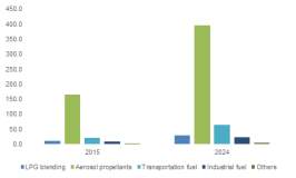
Based on an industry research report in 2015, the market size is projected to exhibit a Compounded Annual Growth Rate (CAGR) of 9.9% by 2024. As explained above, the main growth driving force will be the commercialisation of DME as a transportation fuel, predicted to have a CAGR of 14% by 2024.
This is of particular interest to Australia as one of the world’s largest consumers of diesel. Industry analysis forecast diesel prices to continue elevating in the future and with relatively cheaper DME being available, Australian consumers will be expected to support the use of DME as an alternative. However for the successful implementation of fuel DME, challenges such as production costs and viability of using DME as a diesel alternative need to be carefully considered. It is important to note that in order for DME to have a positive economic effect, production must be considered at a large scale to drive costs down and position fuel DME as a cheaper alternative to diesel.
The next decade could also involve increasing the investment of bio based DME operations. Bio based DME production involves the use of non-fossil fuel produced methanol feedstock and currently, there is only one operational bio based DME plant in the world located in Sweden. With the rising elimination of fossil fuel dependence, the bio based DME market is projected to post significant growth at a CAGR of 11% in the next decade.
3 Location Selection
3.1 Methodology
Location of the DME plant is one of the key factors in the starting stage of the DME industry. It will greatly affect the profitability and social recognition of the new alternative fuel. Aim of this project is to reduce emission of greenhouse gas, carbon dioxide, from the nature gas production, and transform them into DME. Our targeting market is the diesel used in heavy transporting vehicles within Australia. In 2015, 2863 million litters of diesel were consumed for truck transportation. To replace that, 188 thousand tonnes of DME will be produced each year, which will need about 500 million tonnes of CO2.
Nature gas basins produce nature gas which contains 10% to 30% of CO2, which is the carbon source for this project. Four gas basins were selected and compared in details as long as other location factors.
3.2 Selection Criteria
3.2.1 Feedstock Availability
The DME plant together with the gas conditioning plant should be close to the gas field for it would cost less on building pipes and on-land transporting. It will also reduce the need of pumping and storage facilities.
3.2.2 Land availability
Land of the plant should be of industry use. It should be far away from main cities, downwind side of residential area and should not be located on heritage sites or other protected places.
3.2.3 Labour source
This project is not considered to be a labour-intensive initiative. It can create job opportunities in nearby areas. Process engineers, operators and other workers may probably come from neighboring cities. The infrastructure is also an important factor while planning for a new plant. The existing infrastructure in the neighbouring major cities will be preferred, especially for the start-up stage.
3.2.4 Proximity to Markets
Our current target market is transportation fuel blending for trucks. From a long-term perspective, many car manufacturers, such as Ford and Hyundai, are developing new DME fuel cars for higher efficiency and less NOx emission. If these DME fuel cars are largely promoted, they will first appear in modernized cities such as Melbourne, Sydney and Perth. So the DME plant is better to be close to these cities.
3.2.5 Company incentive
Gas producing companies may be very much willing to find opportunities to build by-product plants individually or in a cooperate manner. On one hand, they can reduce the emission of CO2, SO2 and other toxic gases. On the other hand, gas companies can have a good reputation of making less carbon footprint.
3.3 Potential Locations
Table 3‑1. Comparison of four potential locations and key selection criteria.
| Kipper-Turrum | Ichthys | Gorgon | Curtis | |
| * Capacity of CO2 | 436870.93 | 2600422.222 | 5.5-8.8 million tonnes | 5.75 million tonnes |
| * Purity of CO2 produced | 96%-99% ( gas sweetening) | 96%-99% (gas sweetening) | 99.70% | Pure |
| * Current use of CO2 | immediately vented | not yet | 3.4-4 million injection | emission |
| * Lifetime of gas field production | 10 years | 20-30 years | Ends between 2054-2074 | 24 years life from 2014 |
| * Company image/incentives | Exxon | Inpex Corporation | ||
| * Existing infrastructure | gas conditioning plant | not yet | ||
| * Labour | ||||
| * Price of land | 1million for 2289 m2 | 0.72 million for 336 m2 |
3.4 Final Location of DME production Facility
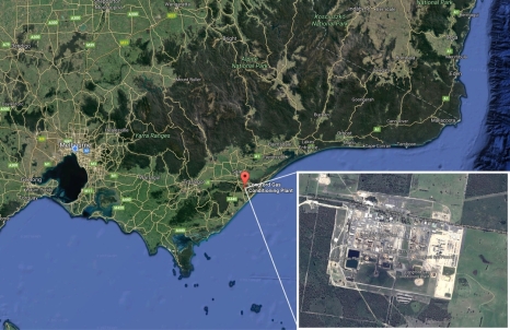
The final decision for the location of this DME plant is using CO2 for the Longford gas conditioning plant of Kipper Tuna Turrum wells in Gippsland basin. The Longford plant is located in Gippsland, together with three gas producing plants. Gippsland is located in Victoria, about 300km east of Melbourne. Kipper Tuna Turrum produce Nature gas containing average 8.5% of CO2. The Longford plant separate CO2 and H2S from the raw gas and present to the DME plant.
4 DME Production Technology
4.1 Overview (Peter)
4.2 CO2 Purification
CO2 is removed from the Longford gas conditioning plant, the assumption was made that there is also some impurity in the CO2 stream such as hydrogen sulfide (H2S), mercaptans(R-SH), carbonyl(COS) and carbon disulfide (CS2). However, the mercaptans, carbonyl and carbon disulfide is negligible compared to hydrogen sulfide, only H2S removal technologies will be discussed here.
There are two main technologies involved with H2S removal, which is liquid phase process (Claus sulfur scavenger) and dry bed process (Metal Oxide process)
Table 4‑1.
| Technologies | Claus Process | Amine | Membranes | Hot Potassium carbonate | Dry bed process |
| Acid Gas Inlet Content (Volume%) | 0-100% | Up to 70% | Up to 90% | 5~50% | 0.1~2% |
| Advantage | High sulfur recovery | Most widely used. | Small footprint, less than 1% V of acid gas at outlet. | Relatively low operational lost | Process are limited to sulfur removal |
| Disadvantage | Amine solution frequently become contaminated
Loss of CO2. |
Used for bulk H2S removal. | Loss of CO2.
High operating temperature |
The amount of sulfur removed is small | |
| Ease of Operation | Medium | Complex | Medium | High Complexity | Medium |
| Cost | High FCI medium OC | Medium FCI
Medium OC |
High FCI
Low OC |
Medium FCI
Low OC |
Sulphur removal from natural gas conditioning plant:
Traditionally the acid gas (CO2, H2S) sweetening process include Claus technology, amine (chemical solvent), membranes, hot potassium carbonate and dry bed process.
The main characteristics of different technology is compared in the table above, Claus process was chosen because it is remove the least amount of CO2 compared to other process and have very high sulfur recovery.
The basic Claus process mix oxygen with hydrogen sulfide, and then pass through a pre-heated catalytic bed. The hydrogen sulfide under a partial combustion is then reacted with Sulphur dioxide with an activated alumina catalyst. The product is pure CO2 stream and sulphur element.
One of the drawbacks for Claus process is if the inlet acid gas contains less than 40mole% hydrogen sulfide, the extra inert present in the feed will reduce the sulfur recovery efficiency. The H2S composition in Gippsland quite small, one way to prevent such problem is by enrich the inlet gas by selectively remove hydrogen sulfide from the regeneration step.
4.3 H2 Generation
Existing technologies summary
| Natural Gas Reforming
(Steam reformation)-SMR |
Biological production | Electrolysis-Coal/Nuclear |
| Thermal cracking | Biomass gasification | Electrolysis-Wind |
| Thermal decomposition | Coal gasification | Electrolysis-Solar Photovoltaic |
| Thermochemical
(Solar or Nuclear) |
Partial Oxidation | Electrolysis- Thermal Power |
| Photochemical | Photo electrochemical |
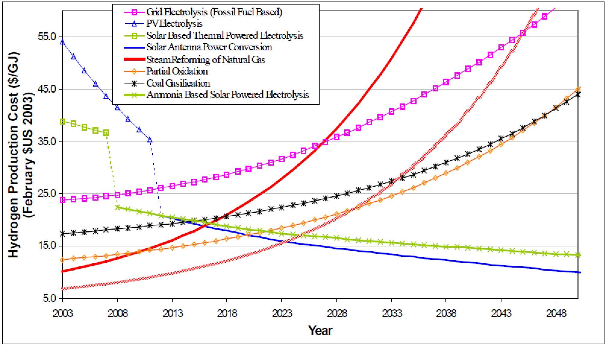
Figure 1: Hydrogen Production Cost Prediction
From figure 1, the fossil fuels based hydrogen production prices are increasing exponentially whereas the renewable energy based hydrogen production are gradually decreasing. In fact, the hydrogen price from natural gas reformation as gone by from XXX to XXX from 2016 to 2017. On other hand, the prediction doesn’t take environmental penalty as such carbon price into consideration. In US, this can be estimated as S15/GJ for a coal feedstock, $13/GJ for a petroleum feedstock and $9/GJ for a natural gas feedstock.
Major Technology comparison:
| Name | Advantage | Disadvantage |
| Natural gas reforming | Lowest Current Cost, Existing methane infrastructure. | High maintenance cost
High operation cost Depends on methane price |
| Coal/Biomass Gasification | Abundant and affordable coal as the feed stock | High reactor cost, low efficiency, impure feedstock. Require pure oxygen |
| Water Electrolysis | No pollution, high purity H2 | Low efficiency and high capital cost |
| Photo electrochemical | Low operating temperature | Low efficiency, small scale |
| Partial Oxidation | Any hydrocarbon as feedstock. High efficiency | High CO2 emission |
| Thermal Cracking | A lot less CO2 compared to SMR. Valuable carbon black product. | Low productivity
High operating temperature |
1. Natural gas reforming
Reforming
Natural gas reforming is also called steam reforming, it converts methane into hydrogen and carbon monoxide as shown in the equation below.
CH4+H2O⇌CO+3H2
The process is estimated 70% efficient. *.
There are three main steps of the SMR, the first step involves steam reaction with methane at 700-800
℃. This step produces a mixture of hydrogen and carbon monoxide which is called syngas.
Water gas shift reaction-two stage shift system
CO+H2O⇌CO2+H2
The second step, the carbon monoxide generated from the first step is reacted over steam to form more hydrogen and itself been oxidized into carbon dioxide. This step is known as water gas shift reaction. The reaction has a high temperature stage(350
℃.) and a low temperature stage(200
℃.)
Purification
The process steam is then cooled and go through a product purification step, include removal of carbon dioxide from liquid absorption or pressure swing adsorption and residue carbon oxides through methanation.
(purity 99.9% with MDEA and PSA unit)
Currently, Natural gas reforming is the highest commercially available method with easy and efficient operation and least expansive cost among all hydrogen production technologies.
(every tonne of hydrogen correspond to every 2.5 tonne of CO2)
2. Concentrator photovoltaic(CPV) Hydrogen Production
CPV essentially use the solar energy to generate electricity and produce hydrogen from electrolysis. The system efficiency and the total production capability is enhanced by combining solar concentration and spectrum splitting.
This convert 40% incident solar energy into electrical energy. Overall 15% efficiency from solar energy to hydrogen.
The CPV System consists two steps for hydrogen production.
Step 1: Solar Energy to electrical energy
CPV dish focuses sunlight on the PV panel. Some energy is reflected from the PV optical filter and the remaining energy is transmitted through the PV panel and transformed into electricity.
Step 2: Renewable electrical energy to hydrogen
The electricity is supplied to the solid oxide electrolyzer cell, and separate the water into hydrogen and oxygen. Heat is also supplied to the electrolyzer cell to reduce electricity demand and also increase process efficiency.
CPV hydrogen production as a prototype, construction cost is relatively high. However, effective design can significantly reduce the hydrogen production cost in the future.
Future Prediction for CPV
| 2003 | 2010 | 2020 | 2030 | 2040 | |
| System Price | $10/W | $4/W | $2/W | $1/W | $0.5/W |
| Electricity Price | $0.2/kWh | $0.15/kWh | $0.06/kWh | $0.04/kWh | $0.03/kWh |
| Performance | 10% | 15% | 20% | 23% | 25% |
4.4 CO2 Hydrogenation to Form Methanol
4.4.1 Using Methanotropic Bacteria
Methanotropic bacteria are able to metabolise methane for energy via conversion into methanol, formaldehyde, formate and finally CO2. The reaction to convert methane to methanol is an irreversible reaction whereas the following reactions are reversible oxidation reactions [1]. Xin et al. (2007) used poly-β-hydroxybutyrate (PHB) as a reductant to reverse the later steps of the metabolic pathway in the methanotrope Methylosinus trichosporium. During their process, a build-up of extracellular methanol was detected which indicated that the pathway was successfully reversed to form methanol out of CO2 and did not proceed to produce methane from the methanol formed [1].
However M. trichosporium needed to be incubated under certain conditions to build up a store of PHB. The build-up of PHB became a limiting factor in the production of methanol in this process. Seven days of incubation only built-up enough PHB to produce an average of 3mmols of methanol per gram of dry cells for the first four days and before tapering off to zero within 3-4 days [1]. After eight batches of methanol production, the M. trichosporium was compared to a control batch of M. trichosporium that hadn’t undergone methanol production to test whether this process affected the bacteria’s ability to grow. Nine days of incubation were required before new colonies grew to a visible size. This scale and rate of production is too low to be economical on an industrial scale.
4.4.2 Using Electrochemical Reduction
Several studies have been performed to explore the potential of using electrolytic cells to reduce CO2 into methanol [2-4]. The principle behind this process is that an electrical potential is applied across two electrodes to reduce carbon dioxide at the cathode and oxidise water at the anode to produce methanol and oxygen according to the following reactions:
Reaction at Cathode:
CO2 + 6H+ + 6e-⇌CH3OH + H2O
Reaction at Anode:
3H2O ⇌1.5O2+6H++6e-
Overall reaction:
CO2+2H2O ⇌CH3OH+1.5O2
However this is not the only possible reaction, there are over 16 possible products that can be formed depending on the configuration of the electrolytic cell [2] which means that selectivity can be a significant problem in these systems. For example the Faradaic efficiency (percentage of electrons supplied to the system that go towards forming the desired product) of a pure copper cathode was found to be 0.8% [4]. Of course there have been many attempts to find a better electrode material such as Cu2O which had a Faradaic efficiency of 38% but the electrode itself was reduced and lost its catalytic ability [4]. Deposition of impurities, side products and intermediates is also a common problem in these systems and is one of the challenges that to be overcome before commercialisation of this technology is implemented [2].
4.4.3 Catalytic Hydrogenation of CO2
This is the conventional method of producing methanol from CO2 [5, 6] and a significant amount of research has gone into understanding and optimising this process. In this process, copper-zinc based catalysts such as Cu-ZnO-Al2O3 are the most commonly used catalysts for converting carbon dioxide and hydrogen gas into methanol [6, 7]. The main chemical reactions of interest are [5, 8]:
Δ
H298K°=–49.5kJ/mol
Δ
H298K°= 41.2 kJ/mol
Δ
H298K°=–90.6 kJ/mol
(R1) CO2 hydrogenation to methanol:
CO2+3H2⇌CH3OH+ H2O
(R2) Reverse water gas shift (RWGS) reaction:
CO2+H2 ⇌CO+H2O
(R3) CO hydrogenation to methanol:
CO+2H2 ⇌CH3OH
R1 is the desired reaction in this process, however the RWGS reaction competes with R1 for carbon dioxide and hydrogen so it is necessary to control the operating conditions to favour R1. Since R2 is endothermic, it is important to extract the heat from the reactor and prevent heat from building up which would promote the endothermic RWGS reaction. The common temperature range for this reaction is 200-300°C with the highest conversion rate occurring around 250-260°C [7, 9].
Another parameter that can be used to promote R1 is pressure. Since R1 causes a reduction of four moles on the left to two moles on the right, R1 is thermodynamically favoured at high pressure and the equilibrium is shifted towards the right [7, 8]. The pressure used is commonly around 50-100bar which has a one-pass conversion across the reactor around 10-20% [6]. However by condensing the methanol and water, and separating the unreacted gases in a flash drum, the unreacted gases can be recycled back as shown in Figure 4‑1 to increase the overall yield of the process to over 90% [9, 10].
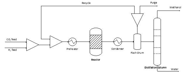
Figure 4‑1. Basic overview of the process to synthesise methanol from CO2 hydrogenation.
Even at ideal temperature and pressures, some carbon monoxide will still form from the RWGS reaction and get recycled back to the reactor. Therefore, commercial catalysts such as Cu-ZnO-Al2O3 are able to catalyse the hydrogenation of CO as well as CO2 so that the overall conversion of carbon oxides to methanol is increased and less waste products are produced [6, 9]. To prevent build-up of other undesired by-products, some of the recycle stream is purged from the system. Finally the condensed methanol and water are separated in a distillation column and the methanol can be sent downstream for conversion into DME.
4.5 Methanol Dehydration to Form Dimethyl Ether
Some processes for DME synthesis use a direct synthesis method where the methanol dehydration is done in the same reactor as the methanol synthesis reactor using a bifunctional catalyst that can also catalyse the methanol dehydration reaction [6, 11]. However for the scope of this study, only the indirect method where methanol is produced in one reactor, separated out and then sent to another reactor to form DME will be examined. The reaction for this step is relatively simple and is shown in R4:
Δ
H298K°=–23.5kJ/mol
(R4) Methanol dehydration [6, 11]:
2CH3OH ⇌CH3OCH3+H2O
The reaction is catalysed by solid acid catalysts or zeolites such as . The reaction takes place at acidic sites on the catalyst, however the strength of these sites can’t be too acidic or else coking of the catalyst and formation of other by-products can occur. γ -Al2O3 is an type of highly porous activated aluminium oxide with high surface area and is commonly used as a desiccant to remove water [12]. Since it has weak to medium strength acidic sites, catalysts for this reaction are often based off γ -Al2O3 [11, 12].
Temperature and water can also inhibit catalyst activity. At temperatures above 300°C, γ -Al2O3 can produce other hydrocarbons from methanol, thereby reducing the selectivity for DME conversion [12]. Since the reaction is exothermic, heat most be constantly removed so that the reactor doesn’t overheat and create unwanted by-products. Water is also produced during the formation of DME and it can adsorb to acidic sites, thus inhibiting the formation of DME [13]. Therefore it is important to fully separate out the water from the methanol before recycling methanol back to the reactor as shown in REF _Ref490039586 h Figure 4‑2Figure 4‑2.
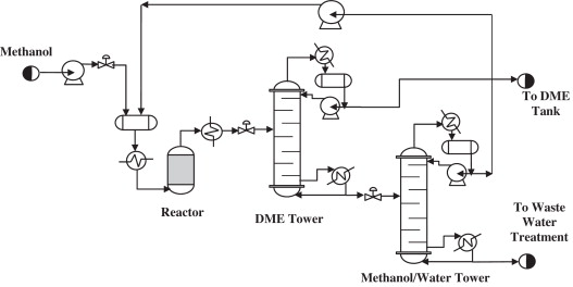
Figure 4‑2. Basic overview of the process for the dehydration of methanol to DME.
There has been much research into the improvement of catalysts for this reaction focusing mainly on γ -Al2O3 based catalysts.
4.6 Future Technologies
5 Economic Analysis
5.1 Project Evaluation
| Description | Value | Reference | |
| Sales volume | Based on the demand of DME as fuel for heavy-duty diesel trucks in Australia | 170,000 t/yr | Refer to section San |
| Sales revenue | Based on a 90% valuation of the diesel price | $650 AUD/t | Refer to section San |
| CO2 income | Income received from the Longford gas plant for the removal of CO2 | $13/tonne of CO2 | Refer to section San |
5.2 Assumptions and Methodology
| Factor | Value |
| Construction period | 2 years (2018-2020) |
| Operational period | 20 years (2020-2039) |
| FCI 1st year percentage | 60% |
| FCI 2nd year percentage | 40% |
| Annual capacity growth | 16.6% till 2030 |
| Depreciation | 10% of FCI for first 10 years |
| Tax rate | 30% |
| Discount rate | 10% (rongkai) |
| Operational days in a year | 365 |
5.3 Cost Estimate Classification
| Description | Cost (AUD) | Reference | |
| Land Cost | 12 ha of industrial land in Longford, Victoria | $15m | Real Estate prices for industrial land in regional Victoria |
| Fixed Capital Investment | CO2 purification
(H2S removal) |
$6.24m | Insert |
| H2 generation | $114m | Insert | |
| Methanol synthesis | $278m | Insert | |
| DME production | $88m | Insert | |
| Working Capital | 15% of the sales revenue for petrochemical industry | Refer to Appendix ? | Insert |
| Fixed Operating Expenditure
(* includes Labour, maintenance, administration and insurance) |
CO2 purification
(H2S removal) |
$630,000 | Insert |
| H2 generation | $0.49 | Insert | |
| Methanol synthesis | $1.32 | Insert | |
| DME production | $19.26m | Insert | |
| Variable Operating Expenditure
(*includes raw materials and utilities |
H2 generation | Refer to Appendix ? | Insert |
| Methanol synthesis | Refer to Appendix ? | Insert | |
| DME production | Refer to Appendix ? | Insert | |
| Carbon Price ? | Based on a survey by the Carbon Market Institute | $15/tonne of CO2 |
5.4 NPV Analysis
5.5 Sensitivity Analysis
6 Social, Environmental & Economic Impacts
The proposed DME plant will utilise the waste stream of the existing natural gas processing plant at Longford as its feedstock by connecting a pipeline their waste gas outlet. This waste will include large quantities of the greenhouse gas carbon dioxide, H2S and low quantities of NOx and SOx (Chevron, 2015). The will reduce greenhouse gas emissions of the natural gas processing plant by using the carbon dioxide as a reactant to produce of dimethyl ether. However during construction and operation periods the plant will emit waste, noise, pollutants to the environment over its lifetime so the environmental, social and economical impacts of the plant will be analysed in this section.
6.1 Environmental
DME project do have environmental impacts especially some issues other than reduction of greenhouse gas emission through processing. During stages including carbon dioxide purification, steam reforming, methanol synthesis and dimethyl ether synthesis, environmental impacts are under assessment considering specific areas – water, air, land, biodiversity and waste management as illustrated below.
6.1.1 Impact on Water and Air
Current supervision on air quality in Australia is the National Environment Protection (Ambient Air Quality) Measure (Ambient Air Quality NEPM) (government, 2017). Important contaminants during stages are carbon dioxide, natural gas, hydrogen, methanol and dimethyl ether.
Impacts on air is majorly caused by carbon dioxide excessive emission which is widely known as chief culprit of global warming. During steam reforming stage, methane reacts with water generating carbon monoxide and hydrogen followed by side reaction which consumes carbon monoxide and water in producing carbon dioxide and hydrogen. Such reaction is purposed as our hydrogen source, meanwhile, generating large quantities of carbon dioxide. Spare impact on air comes from carbon dioxide purification, producing small quantities of H2S, NOx and SOx within degree below Australian standard with potential small impact on local PM2.5.
Major impact on water comes from methanol spill. Potential spills occur during truck or railway transportation. Underground water containing overdose methanol is considered toxic to human and animals which is likely to cause metabolic acidosis, neurologic sequelae, and even death (Korabathina, 2017). However, methanol is considered as a source of ubiquitous energy to anaerobic microorganisms in natural. Natural loss of methanol in water happens due to biodegradation as fast as 80% more percent loss in 24 hours (Ng-Tech, 2017).
6.1.2 Impact on Land
Such project is estimated to use more than thousand square meters rural land in industrial zone. Original vegetation systems are likely to by destroyed during construction period. Buildings on the ground and pipelines underground are considered harmful to local flora and fauna by shrinking their habitat space and destroying their existing food chain. During over 20 years lifespan of the project, toxic contaminants potential existence in soil, underground water and surface water are likely to erase land quality. Accumulating wastes such as metal catalysts are likely to cause irreversible damage to local land and ecosystem.
6.1.3 Impact on Biodiversity
Unrecoverable damage to local ecosystem during both construction and operation periods are under risk to affect local biodiversity. Current national regulation on protecting biodiversity is Environment Protection and Biodiversity Conservation Act 1999 in which national government illustrates important flora, fauna, ecological communities and heritage places to be protected. Nearest reserve park is Dowd Morass Wildlife Reserve located in about 12km north to selected plant site. Major threat to the reserve is water pollution from our project. Potential harm comes from heavy metal overdose in rivers serving as drinking water to animals in the reserve. Methanol overdose is likely to happen as well. Considering biodegradation, the impact in under range.
6.1.4 Waste management
Solid wastes generated throughout stages including used metal catalysts, tailing materials during construction, abandoned pipelines and other normal wastes are purposed to collected in site and delivered to nearest landfill – Kilmany Resource Recovery Centre and Landfill, which is located northwest to the site about 30km away. Transportation route is through C496 highway to Longford before C440 to Sale town, then through A1 to landfill.
As during whole process, pure water is important both as reactant and product in different stages, pure water removal pipelines and water storage tanks are going to be constructed in site. To deal with other liquid mixtures such as methanol-water mixture, several waste treatment pools are going to be built. The treatment pools are designed to be covered or exposed to air depends on volatility of specific liquid under treatment.
Tailing gases are going to be collected either for flare or direct emission after treatment below standard of State Environment Protection Policy (Ambient Air Quality) (Victoria, 2017).
6.2 Social
For social impact on local people, a new chemical plant provides both positive effect such as work opportunities and negative effect such as noise pollution.
6.2.1 Public acceptance
The DME Plant is located right in the industrial zone of Longford beside existing Esso Australia’s Longford Gas Conditioning Plant. With respect to local community and maintaining regular communication with local citizens, a hearing is to be held between plant administrators and local people. On the hearing, plant administrators are obligated to present any safety concerns, environmental impacts and other potential consequences generated by the plant before public questioning. Agreement to the construction and operation between plant administrators and local citizens is essential before plant construction. Plant administrators are also obligated to acknowledge and educate local citizens about safety instructions and self-protection measures.
6.2.2 Noise Level
Machinery working during construction and operation period may generate heavy noise which may threaten local workers and operators employed and citizens under risk of hearing loss if experience long time. Hearing loss is a major hazard in oil and gas industries in Australia. Current Australia standard for protecting people from noise injury is the model Work Health and Safety Regulations(WHS). WHS regulates that over an eight-hour shift a worker can’t be exposed to more than 85 decibels and a worker can’t be exposed to a noise level above 140 decibels (Safework-Australia, 2017). Current measurements dealing with noise issue are working time regulation for operators, peak noise level regulation for machinery and regular hearing tests among workers under risk.
6.2.3 Local infrastructure
DME plant is estimated to employ 200 more employees undertaking construction work and provide 30 more jobs during operation period about 20 years plant lifespan. Nearest town to plant site is Longford – about 12km northwest. Longford has a population of 1,497 people (Australian Bureau of Statistics, 2016). Nearest state suburb is Sale with a population of 13,672 (Australian Bureau of Statistics, 2016). The increment of local population either in Longford or in Sale may result in large demand on local infrastructure during construction period.
Major challenge is the demand on accommodation during construction period. As local real estate market is not likely to provide essential number of houses for 200 more new families moved in during short period, new agents are needed for construction of temporary accommodations. Besides, demand on education, medical support, family support, public security, public community facilities like parks, shopping centre, car parking zone and so on, may also bring fast increase in local market. However, potential absence after construction period of these floating population may cause market jump which is also considered as a threat to local market.
6.2.4 Employment
DME plant is about to provide 200 more work opportunities in construction period and 30 more employment in operation period. This gives positive impact on solving local unemployment. Currently Sale has an unemployment rate of 5.4% (Qpzm, 2017) while East Gippsland Shire has 1,776 unemployed people which consists 8.66% of local resident workers on March 2017 (Idcommunity, 2017). Local regional rate of unemployment is much higher than average national figure of Australia (5.9%) at the same time (Idcommunity, 2017). Our new plant is estimated to make contribution of 1% decrease in the rate of local unemployment.
6.3 Economic
Increment of population during plant construction period is surely to bring benefits to local market. Meanwhile, working opportunities are also provided by such new plant during both construction and operation periods in plant lifespan.
6.3.1 Local Economic Opportunities
New plant will certainly regard local skilled and educated unemployed people as their first priorities to hire both in construction and operation periods. New moved in employees with their families may also bring new opportunities to local market as their normal demand on food, medicine, education, accommodation and others promotes market trades and increases household income of local citizens. Tax income for local government from such new plant will support more construction of local infrastructure.
As a new product to replace diesel in the near future, local oil market will be the first trial target market to apply such new product, which may change lifestyle of local people. Serving price will be lower than other places due to low transportation cost. New designed trucks may be applied to local market as well with potential to promote increment in truck trading price. Other products associated to such new plant may also bring economic benefits to local market.
6.3.2 Market Competitors
DME product is regarded as a replacement of diesel fuel in the near future. Currently in Australia, major diesel fuel suppliers are Costco, Puma Energy, BP, Caltex, Coles Express Shell, Metro Petroleum, Mobil 7 Eleven, Shell, United Petroleum and Woolworths Caltex (Canstarblue, 2017).
6.3.3 Macroeconomic Impacts
More than positive impact on local economy, DME project is surely to make great contribution to national Gross Domestic Product (GDP). Rough formula for calculation of GDP is
GDP = C + I + G + (X – M)
Where C refers to Consumption, I refers to Investment, G refers to Government, (X-M) is Net Export calculated by exports minus imports (Investopedia, 2017).
National consumption on DME is increasing by forecast as a replacement of diesel fuel in the near future. Personal consumption on daily goods is likely to increase indirectly as such new fuel applied to market. Investment arise has direct impact on GDP due to large investment in such plant. Meanwhile, government behaviours in expansion on local infrastructure is considered direct positive impact to GDP as well. Net Export value is considered equal with its potential increment in the future depending on international demand of DME product.
11 Bibliography
Australian Bureau of Statistics. (2016). 2016 Census QuickStats. Retrieved from http://www.censusdata.abs.gov.au/census_services/getproduct/census/2016/quickstat/SSC21526?opendocument
Canstarblue. (2017). Petrol & Service Stations. Retrieved from Costco, Puma Energy, BP, Caltex, Coles Express Shell, Metro Petroleum, Mobil 7 Eleven, Shell, United Petroleum and Woolworths Caltex
CCF Group. (2016). Dimethyl ether’s awkward plight in China. Retrieved 7 30, 2017, from http://www.ccfgroup.com/newscenter/newsview.php?Class_ID=D00000&Info_ID=20160311065
Chevron. (2015). Gorgon Gas Development and Jansz Feed Gas Pipeline. Gorgon: Chevron Australia. Retrieved from https://www.chevronaustralia.com/docs/default-source/default-document-library/gorgon-emp-best-practice-pollution-control-design-report.pdf?sfvrsn=4
Global Market Insights Inc. (2016). Dimethyl Ether (DME) Market Size By Raw Material , By Application , Industry Analysis Report, Regional Outlook, Application Potential, Price Trends, Competitive Market Share & Forecast, 2013 – 2024. Delawere: Global Market Insights Inc.
Gough, M. (2016, 8 9). DME: the answer to Australia’s unquenchable appetite for diesel? Retrieved 7 27, 2017, from https://www.theguardian.com/sustainable-business/2016/aug/09/dme-the-answer-to-australias-unquenchable-appetite-for-diesel
government, A. (2017). Retrieved from http://www.environment.gov.au/protection/air-quality
Idcommunity. (2017). East Gippsland Shire Unemployment. Retrieved from http://economy.id.com.au/east-gippsland/unemployment
Investopedia. (2017). GDP. Retrieved from http://www.investopedia.com/exam-guide/cfa-level-1/macroeconomics/gross-domestic-product.asp
Korabathina, K. (2017, Jan 31). Methanol Toxicity. Retrieved from http://emedicine.medscape.com/article/1174890-overview
McKone, T., Rice, D., Ginn, T., Bastani, M., Levy, A., Lenhart, A., . . . Bourdeaux, R. (2015). California Dimethyl Ether Multimedia Evaluation. California: The University of California.
Ng-Tech, E. (2017). Environmental Issues. Retrieved from http://emsh-ngtech.com/methanol/environmental-issues/
Qpzm. (2017). Sale Demographics (VIC) Local Stats. Retrieved from http://sale.localstats.com.au/demographics/vic/south-eastern-victoria/gippsland/sale
Safework-Australia. (2017). Noise. Retrieved from https://www.safeworkaustralia.gov.au/noise
Syed, A., Nowakowski, D., Nicholson, P., & Ahmed, S. (2014). Australian Liquid Fuels Technology Assessment. Canberra: Bureau of Resources and Energy Economics.
Victoria, E. (2017). Air legislation. Retrieved from http://www.epa.vic.gov.au/about-us/legislation/air-legislation#sepp_ambient_air
Appendix A:
Appendix B:
Appendix C:
1. Xin, J.-y., et al., Methanol production from CO2 by resting cells of the methanotrophic bacterium Methylosinus trichosporium IMV 3011. Journal of Basic Microbiology, 2007. 47(5): p. 426-435.
2. Albo, J., et al., Towards the electrochemical conversion of carbon dioxide into methanol. Green Chemistry, 2015. 17(4): p. 2304-2324.
3. Le, M., et al., Electrochemical Reduction of CO2 to CH3OH at Copper Oxide Surfaces. Journal of the Electrochemical Society, 2011. 158(5): p. E45-E49.
4. Jia, F., X. Yu, and L. Zhang, Enhanced selectivity for the electrochemical reduction of CO2 to alcohols in aqueous solution with nanostructured Cu–Au alloy as catalyst. Journal of Power Sources, 2014. 252: p. 85-89.
5. Atsonios, K., K.D. Panopoulos, and E. Kakaras, Investigation of technical and economic aspects for methanol production through CO2 hydrogenation. International Journal of Hydrogen Energy, 2016. 41(4): p. 2202-2214.
6. Álvarez, A., et al., Challenges in the Greener Production of Formates/Formic Acid, Methanol, and DME by Heterogeneously Catalyzed CO2 Hydrogenation Processes. Chemical Reviews, 2017. 117(14): p. 9804-9838.
7. Bansode, A. and A. Urakawa, Towards full one-pass conversion of carbon dioxide to methanol and methanol-derived products. Journal of Catalysis, 2014. 309: p. 66-70.
8. Shen, W.-J., et al., Thermodynamic investigation of methanol and dimethyl ether synthesis from CO2 Hydrogenation. Korean Journal of Chemical Engineering, 2000. 17(2): p. 210-216.
9. Fornero, E.L., et al., CO2 capture via catalytic hydrogenation to methanol: Thermodynamic limit vs. ‘kinetic limit’. Catalysis Today, 2011. 172(1): p. 158-165.
10. Pérez-Fortes, M., et al., Methanol synthesis using captured CO2 as raw material: Techno-economic and environmental assessment. Applied Energy, 2016. 161: p. 718-732.
11. Azizi, Z., et al., Dimethyl ether: A review of technologies and production challenges. Chemical Engineering and Processing: Process Intensification, 2014. 82: p. 150-172.
12. Osman, A.I., et al., Effect of precursor on the performance of alumina for the dehydration of methanol to dimethyl ether. Applied Catalysis B: Environmental, 2012. 127: p. 307-315.
13. Hosseininejad, S., A. Afacan, and R.E. Hayes, Catalytic and kinetic study of methanol dehydration to dimethyl ether. Chemical Engineering Research and Design, 2012. 90(6): p. 825-833.
Cite This Work
To export a reference to this article please select a referencing stye below:
Related Services
View all


Related Content
All TagsContent relating to: "Technology"
Technology can be described as the use of scientific and advanced knowledge to meet the requirements of humans. Technology is continuously developing, and is used in almost all aspects of life.
Related Articles

DMCA / Removal Request
If you are the original writer of this dissertation and no longer wish to have your work published on the UKDiss.com website then please: