Architectural Causes of the World Trade Center Buildings Collapse
Info: 9402 words (38 pages) Dissertation
Published: 9th Dec 2019
Tagged: Architecture
Contents
Weight of steel per floor above the ninth floor
Abbreviations and Notation
WTC1 World Trade Centre 1 (North Tower)
WTC2 World Trade Centre 2 (South Tower)
L Length of each side of the towers
H1 Height of WTC1
H2 Height of WTC2
Abstract
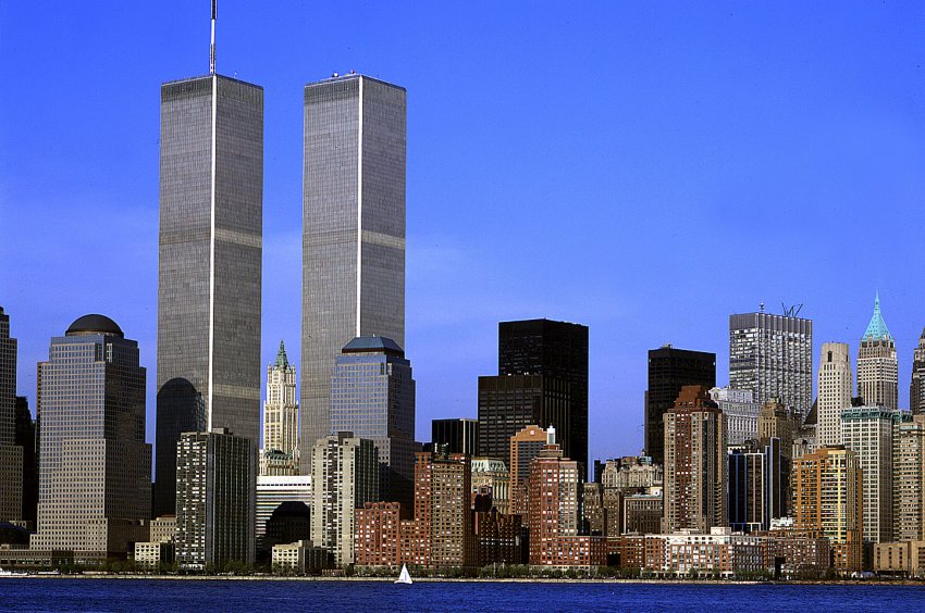
September 11th, 2001 was one of those days everyone remembers were they were the moment the news broke about a plane crashing into the World Trade Center in New York. I had just finish my lunch break at that time and saw the towers on tv and heard the commentator saying a small plane crashed into it, I immediately thought that the surface area where the plane crashed was far too wide an opening to be a small aircraft.
Ever since then I have researched credible and non-credible theories to try and determine how two 110 storey steel framed buildings collapsed into its own footprint at nearly free-fall speed. This dissertation is focused on what can be proven that happened on that day, with my own analysis derived to determine the probable events that lead to the collapse of the buildings. To do this I Calculated the area and mass of the upper section above the impact zone of both towers. The aim of this dissertation is to derive the approximate kinetic energy that was released, to crush the lower section, and a simple impact load experiment. Also calculated is a composite floor design for the beam framed and truss framed floor system spanning in each orientation with loads acting on the floor.
Introduction
Skyscrapers are a unique American art form. Born in the late 19th century (Douglas, 2017) with the revolution in the steel industry and the invention of the elevator, building design at the time was transformed. Near the end of the 19th century, buildings only reached 10 stories, walls were designed to be thick at the bottom to support the weight above, therefore the higher the building, room space had to decrease. The Second Rand McNally Building in Chicago was the first to use steel cage construction. The weight of the building was no longer supported by the exterior walls, instead, it was supported by the mass of the interior columns.
In the 1930s multi-story steel construction reached its limitations, the Empire State Building stood tallest in the sky at that point. With the great depression and economic downturn, it remained the tallest building in the world because its way of design also reached its peak, the lowest level had to support itself, plus every level above, the upper floors had to decrease in size the higher it was built. The cost to construct such a building again of its type was very expensive, and after the great depression ended that kind of finance was unavailable for anything else let alone another structure.
The idea of the establishing the World Trade Center (WTC) in New York City was first proposed in 1943. During the late 1940s and 1950s, economic growth in New York City was concentrated in midtown Manhattan. To help stimulate urban renewal in Lower Manhattan, after some delays in who would take responsibility for the project, the Port Authority was requested with the role of building the WTC, forty years later these super iconic structures will surpass the Empire State Building, sky-scraper design was about to be revolutionized.
On September 20th, 1962 the Port Authority announced the appointment of Minoru Yamasaki a renowned Architect from Seattle, he selected Structural Engineer Leslie Earl Robinson, an up and coming American engineer. Together they were not only going to design and construct two 110-story buildings but to change all aspects of the original designs before them and redefine the Manhattan skyline, 1966 demolition commenced, in 1968 steel construction began.
Two grazing rectangular sculptures above the city, floors would not taper at the top, each floor approximately 4000m2, open office space (OOS) would be identical from top to bottom. Therefore, the buildings would be more profitable, steelwork primarily on the outside and the internal core, no columns required in between, giving maximum space for tenants.
Dense steel perimeter walls were the hallmark of Yamasaki’s design, square hollow tube plates welded together, core columns made of more standard steel carried to the bulk weight of the load from the building. In between that space, lightweight steel trusses made up the floor span, connecting the perimeter tubes to the internal core, which will be analysed in this document.
Literature Review
In order to understand how a building collapsed, we must understand how it was built and the sequence of events that lead to its destruction, it must be noted that this topic is extremely sensitive and political. Topics discussed include, the structures description, materials, connections, and design performance. Temperature in which steel loses strength, melting temperature of aluminium, the effect of the jet impact, resulting in localised collapse with debris acting as a cocoon that would raise the temperature, the structures response to the fire loading, sagging floor due to heat, (thermal expansion) sagging tensile strength overcome by sheer weight, perimeter / core weakening, buckling, energy generated, gravitational load and component failures leading to the progressive collapse of the buildings.
The main task for this dissertation is to establish factors for the collapse of the towers, impact zone, what components failed, floor method of construction, the floor truss, columns and loading, detailed connections. The core research for this project will be the National Institute of Standards Technology (NIST) conducted under the authority of the National Construction Safety Team (NCST) Act signed into law October 2002, the observations and findings of the final report released in September 2005. The focus will be on the external, internal tubes / columns their robustness and redundancy, paying attention to the floor design and roof top structure (hat-truss). Design chapter will include lightweight composite truss design and composite beam framed floors used for mechanical rooms and floors above and below them, also impact of the top block above the impact zone and the potential energy it released during initiation of the collapse and how it generated further mass and momentum as it progressively collapsed, units were collected in imperial and converted into metric.
1968 Building codes, what regulations were in place at the time of construction? Fire protection of the steel for example. Comparison of what they are today. Fire Protection on steel members, dislodged by impact of the plane
Various credible arguments will also be discussed relating to the structure of the towers and my own emphasis will be concluded,
Structural Components
The Core
To a structural engineer, a skyscraper is modelled as a large cantilever vertical column. Each tower was supported by a structural core extending from its foundation to the roof. The towers and thus the core was divided into three sections separating these sections were the mechanical floors, the size and thickness of the steel core were tapered in each section. The cores were rectangular pillars with numerous large columns and girders, measuring 87 feet by 133 feet. The cores had their own flooring systems, which were structurally independent of the floor diaphragms that spanned the space between the cores and the perimeter walls. The core structures, like the perimeter wall structures, were 100 percent steel-framed and supported 70 percent of the downward force it had 47 steel columns rising 110 stories high, it housed the emergency elevators and stairways and other services, and to my surprise was only insulated with gypsum wallboard and spray on fire proofing SFRM, it did not have a reinforcement concrete wall above the ninth floor
Pic
The Outer Walls
Next to the columns the perimeter walls consisted of dense grids of vertical steel columns and horizontal spandrel plates. These, along with the core structures, supported the towers. In addition to supporting gravity loads, the perimeter walls stiffened the Towers against lateral loads, they carried their own weight and about 30% of the downward force of the building. They distributed the horizontal force to other columns in case of structural failure via the vierendeel spandrel plates welded to the columns. They formed 59 columns on each side with the 60th in the corner so 240 in total, the walls carried half of the floor space the core carried the other half. The spandrels connect the wall columns and regulate the horizontal force distribution
Pic
Hat Truss
The hat truss (outrigger truss) was a lattice of large diagonal I-beams that connected the perimeter walls to the core structure between the 107th floor and roof. It regulated the wind force, carried the antenna on WTC1 and redistributed downward forces to other columns in case of local structural failure. In case of structural failure in the core, the weight of the failing columns is redistributed via the hat truss to other columns in the core or the walls. The hat trusses are central to the probable collapse sequence described by NIST’s Final Report on the Twin Towers they determined that the hat truss transferred column instability between the core structures and the perimeter walls.
Pic
Floor
Floor trusses were pre-fabricated, made up of steel bar joists, bridging trusses and metal deck, optimised to be as light-weight as possible, so they could be easily transported, fitted and relatively cheap to assemble. When the trusses were fitted into place a lightweight concrete floor was poured on top Pic compared to wall The floors of the Twin Towers completed the structural system whose main elements were the core structures and the perimeter walls. The floor diaphragms were annular structures that spanned the distance between the core structures and the perimeter walls, providing large expanses of uninterrupted floor space. The cores had their own flooring systems, which were structurally independent of the surrounding floor diaphragms. The floor diaphragms consisted of lightweight concrete slabs poured onto corrugated steel pans, which were supported by trusses. Primary double trusses were interwoven with transverse secondary trusses. For the truss framed floor steel studs were not included in floor design for floor outside the core, instead the web diagonal (knuckle) projected above the top chord which made the floor truss, metal deck and concrete slab act in a composite manner.
Pic
Design Chapter
Floor Design:
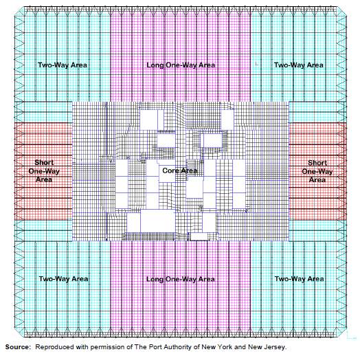
For the vast majority of floors, the area outside the core of a typical floor was supported by a series of approximately, 2ft 5 in. (0.76m) deep floor trusses (National Construction Safety Team Act Reports 2005, NIST NCSTAR – 1-3 p.10). When installed they connected the interior to the exterior onto angled brackets, with two bolts at each end, then welded for added strength. The floor trusses were 60ft (18.3m) or 35ft (10.7m) in length, fabricated 26ft (8.0m) wide, depending on the relative orientation and spaced at 6ft 8 in. (2.0m) apart, each floor was separated into three sections, two long one-way spanning areas, two short-way spanning areas and four two-way spanning areas.
Once the full floor sections were in place a concrete floor was poured, then the steps were repeated for each floor. There were dozens of variations which included difference in length for the top and bottom chord size, bearing angles at truss ends, size of web diagonals and presence or absence of chord plates. Floor types also varied which included mechanical floors which were all beam framed floors, they were grouped into two or three floors throughout the height of the building and carried heavy mechanical equipment, which was strengthened by structural steel frame slabs. They were designed to distribute the equipment weight laterally, but they could neither arrest the vertical collapse of WTC towers nor reduce the collapse velocity. They were not designed for that purpose anyway. When the crush font reached these floors, the accumulated kinetic energy was already far higher than the energy required to crush these frames. A calculated analysis will be expressed as follows:
Buildings Dimensions
- Gross area of each tower above ground level (AG)
where:
L = 208ft (63.4m)
H1 = 1,368ft (417m), which supported a 360ft (110m) tall antenna,
H2 = 1362ft (415m)
N = 110 (above ground level)
Area per floor (Af) = 208 x 208 = 43,264 sqft (4,020m2)
⸫ AG = 43,264 x 110 = 4,759,040 sqft (442,200m2) above ground level
Now that we have a understanding shear size of the towers, let’s delve into some of the geometric properties structural materials to gain a understanding of the buildings structure
Composite Beam Framed Floors
- Mechanical floors 7, 8, 41, 42, 74, 75, 76, 108 and 109
Note: Design example and equations used to Eurocode 4 specificaion, Composite Beam Design, Eurocode 4, R.M Lawson and K.F Khung (1994) dimensions and loadings are collected from NIST NCSTAR 1-1A, calculations are converted into metric units
Slab was designed for 2 hour fire rating (NIST NCSTAR 1-6B, p21)
Floor dimensions,
L1 = 60 ft (18.3m) L2 = 32 ft (10.7m)
b = 3.28 ft (1.0m)
ht1 = 5.74 in. (146mm) ht2 = 7.75 in. (197mm)
hc1 = 4.25 in. (107.9mm) hc2 = 6.25 in. (158.9mm)
hp = 1.5 in. (38.1mm)
Shear Connectors:
19mm dia studs (ds) x 114.3 overall length, after weld = 108.3mm (hs)
Materials:
Steel grade,
fy 50ksi, A572 steel, equivalent to S355, nominal strength 355N/mm2
t = 16 < > 40, were t is the thickness part of the member
γa = 1.05 (partial safety factor)
Ꞙd =
fyγa =
3551.05= 338 N/mm2
Concrete,
Class was not determined in any of NIST reports therefore,
Density, ρd = 150 pcf (23.56kN/m3) for typical mechanical floor (NWC)
Design compressive strength (NIST NCSTAR 1-2A, p56), fck = 3,000 psi (20.68 N/mm2)
Assume class: C20/25, table 1 (IRL) compressive strength of NWC concrete
Loading:
- Concrete Slab
Include comflor autocad with variables
Slab weight on mech floor, Cw1 =
ht- hpb Dv+Dv4 ρd
⸫ Cw1 =
146×103- 38.1.1 44.5+11.25x 23.56 /106 = 2.94 kN/m2
Slab weight above mech floor, Cw2
Cw2 =
197×103- 38.1.1 44.5+11.25x 23.56 /106 = 4.14 kN/m2
Permanent loads:
- Construction Stage, Psf (kN/m2)
Slab reinforcment = 3 0.15
Steel deck = 2 0.096
Self weight of beam = 20 0.96 ____ ____
Total = 94 Psf , (4.5 kN/m2)
Construction load = 10.5 Psf 0.5 kN/m2
- Composite Stage
Concrete slab = 69 3.3
Slab reinforcment = 3 0.15
Steel deck = 2 0.096
Self weight of beam = 20 0.96 ____ ____
Total = 94 Psf, (4.5 kN/m2)
Ceiling and services = 41 Psf 1.96 kN/m2
Super imposed live load
Occupancy = 75 3.59
Partitions = 75 3.59
_____ _____
Total = 150 Psf 7.18 kN/m2
- Beam size and section properties
According to NIST NCSTAR 1-3, p12 beam framed floors were typically W27 beams for the one-way longspan, and W16 beams in the one-way short span direction.
The number after the W represents the nominal depth of the beam, W27 beam had a weight of 114 lb/ft (170 kg/m) and W16 beam had a weight of 49.7 lb/ft (74 kg/m)
- Beam used both spans: 686 x 254 x 170 Grade: S355
h = 692.9 mm d = 615.1 mm
b1 = 255.8 mm Aa = 217 cm2
tw = 14.5 mm Iay = 170300 cm4
tf = 23.7 mm Wpl.y = 5631 cm3
c = 255.8 / 2 = 127.9 mm
fy = 355 ⸫ ϵ =
235355 = 0.81
Section classification
c/tf = 5.4 < 10ϵ = 8.1
d/tw = 42.4 < 72ϵ = 58.3
⸫ Cross section was class 1
- Construction Stage
Ultimate limit state loads
Permanent load factor γG = 1.35
Variable load factor γQ = 1.5
Slab + Beam = 4.26 x 1.35 = 5.75 kN/m2
Construction = 0.5 x 1.5 = 0.75 kN/m2
_____
6.50 kN/m2
Total longspan design load, FL1 = 6.5 x 18.3 x 1 = 119 kN
Longspan design moment, Msd,L1 = (119 x 18.3) / 8 = 272 kNm
Moment resistance of beam
Mapl.RD = Wpl . Ꞙd = (5631 x 338) / 103 = 1903 kNm
> 272 ⸫ OK
⸫ Longspan beam had very high satisfactory positve moment resistance for construction stage.
Total shortspan design load, FS1 = 6.5 x 10.7 x 1 = 70 kN
Shortspan design moment, Msd,S1 = (70 x 10.7) / 8 = 93.6 kNm
Moment resistance of beam
Mapl.RD = Wpl . Ꞙd = (5631 x 338) / 103 = 1903 kNm
> 272 ⸫ OK
- Composite Stage
Ultimiate limit state loads
Slab + beam = 4.26 x 1.35 = 5.75 kN/m2
Ceiling and services = 1.96 x 1.35 = 2.7 kN/m2
Imposed load = 7.18 x 1.5 = 38.7 kN/m2
______
47.15 kN/m2
Total long-span design load = FL2 = 47.15 x 18.3 x 1 = 860 kN
Long-span design moment = Msd,L2 = (860 x 18.3) / 8 = 1967 kNm
Long-span, compressive resistance of slab, (Rc1)
Rc1 = 0.45fcu . beff . hc
Assuming Beff = 1.0m
⸫ Rc1 = 0.45 x 25 x 1000 x 107.9 / 103 = 1,214 kN
Short-span, compressive resistance of slab, (Rc2)
Rc2 = 0.45 x 25 x 1,000 x 158.9 / 103 = 1788 kN
Tensile resistance of steel section, (Rs)
Rs = fd . Aa
⸫ Rs = 338 x 217×102 / 103 = 7,335 kN
Rs > Rc, plastic netural axis falls into beam, therefore the moment resistance of the composite beam is as follows:
Mpl,RD1 =
Rs . h2+Rc (hc2+hp)
=
7,335 . 692.92+1,214 (107.92+38.1) = 2,653 kNm
Mpl,RD2 =
7,335 . 692.92+1,788 (158.92+38.1) = 2,751 kNm
> Msd ⸫ OK
Shear connector resistance, (PRd)
PRd = 0.29 . α . d2
(fck . Ecm)/ γv or PRd = 0.8 . fu ( π . d2 / 4) / γv
Use smallest PRd value
where:
ds = 19mm, hs = 108.3mm, fu = 450 N/mm2
γv = 1.25 fck = 20.68 N/mm2 Ecm = 30 kN/mm2
hs / ds = 108.3 / 19 = > 4 ⸫ α = 1.0
⸫ PRd = 0.29 x 1.0 x 192
(20.68 x 30 x10-3)/ 1.25 = 66 kN
or PRd = 0.8 x 450 (π x 192 / 4) / 1.25 = 82 kN
Long-span vertical shear
Beam and slab = 4.26 x 1.35 x 18.3 x ½ = 52.6 kN
Ceiling and services = 1.96 x 1.35 x 18.3 x ½ = 24.2 kN
Imposed load (SLL) = 7.18 x 1.5 x 18.3 x ½ = 98.5 kN
⸫ Total long-span shear force, VSd = 175.3 kN
Short-span vertical shear
Beam and slab = 4.26 x 1.35 x 10.7 x ½ = 30.8 kN
Ceiling and services = 1.96 x 1.35 x 10.7 x ½ = 14.2 kN
Imposed load (SLL) = 7.18 x 1.5 x 10.7 x ½ = 57.6 kN
⸫ Total short-span shear force, VSd = 102.6 kN
Shear Resistance
Vpl,Rd = Av .
Ꞙd3 were, Av = h . tw
⸫
692.9 x 14.5 x 3383 x 103 = 1961 kN
0.5 Vpl,Rd = 980 kN > VSd = 102.6 kN ⸫ OK
Deflections
- Long – span, non – composite stage deflection, (δL)
UDL = 4.26 kN/m2 (self weight of slab and beam)
Design load, F = 4.26 x 18.3 x 1 = 78 kN
⸫ δL =
5 . F . L3384 . Ea . Iay =
5 x 78 x 183003384 x 210 x 170300 x104 = 17.4 mm
- Short – span, non – composite stage delflection, (δS)
δS =
5 x 78 x 107003384 x 210 x 170300 x104 = 3.48 mm
Composite stage deflection, (δC)
- Long – span, composite stage deflection, (δCL)
UDL = 7.18 kN/m2 (Imposed)
Design load, F = 7.18 x 18.3 x 1 = 131 kN
- Short – span, composite stage deflection, (δCS)
UDL = 7.18 kN/m2 (Imposed)
Design load, F = 7.18 x 18.3 x 1 = 131 kN
Second moment of area of composite section based on elastic properties, (Ic)
Ic =
Aa h+2hp+hc24 ( 1 + n . r)+
beff . hc3 12 . n+ Iay
r1 =
Aa beff . hc1=
217 x 1021,000 x 107.9 = 0.2
r2 =
Aa beff . hc2=
217 x 1021,000 x 158.9 = 0.14
n = Modular ratio = 10 for normal weight concrete
⸫ IC1 =
217 x102 692.9 + 2 x 38.1 + 107.924 ( 1 + 10 x 0.2)+
1,000 x 107.9312 x 10+ 170300 x104
= 3.1 x109 mm4
IC2 =
217 x102 692.9 + 2 x 38.1 + 158.924 ( 1 + 10 x 0.2)+
1,000 x 158.9312 x 10+ 170300 x104
= 3.29 x109 mm4
Vibration simplified method
Slab and beam = 4.26 kN/m2
Ceiling and services = 1.96 kN/m2
10 % of Imposed load = 0.718 Kn/m2
Total = 6.94 kN/m2
Total weight of floor long-span, FL = 6.94 x 18.3 x 1 = 127 kN
Total weight of floor short-span , FS = 6.94 x 10.7 x 1 = 74.3 kN
- Incresing Ic by 10% to allow for dynamic stiffness of composite beam
IC1 = 3.1 x109 x 1.1 = 3.41 x109 mm4
IC2 = 3.29 x109 x 1.1 = 3.619 x109 mm4
Instantanous deflection caused by re-application of self-weight of floor and beam to composite beam, δa
⸫ δL
5 x 127 x 18.3 x1033384 x 210 x 3.41 x109 = 14.15 mm
δS
5 x 74.3 x 10.7 x1033384 x 210 x 3.619 x109 = 1.56 mm
⸫
Natural frequncy long-span =
18√δL =
18√14.15 = 4.79 Hz
Natural frequncy short-span =
18√δS =
18√1.56 = 14.4 Hz
both spans > 4 Hz ⸫ OK
⸫ Composite beams were satifactory under vibration
Composite Truss
Loadings Psf kN/m2
Concrete, steel deck and self-weight, 50.0 2.39
Ceiling and services, 8.0 0.38
58 Psf 2.77 kN/m2
Factor of safety, 2.77 x 1.4 = 3.88
Imposed, 65 Psf 3.1 kN/m2
3.1 x 1.6 = 4.96
Total = 8.84 kN/m2
Span of truss diagram
⸫ WL = 8.84 x 18.3 x 1 = 162 kN
WS = 8.84 x 10.7 x 1 = 95 kN
Max bending moment,
ML =
WL18 =
162 x 18.38 = 370 kNm
MS =
WL28 =
95 x 10.78 = 127 kNm
CAD DIAGRAM
| Angle 76x50x8 | A1 | ӯ1 | A2 | ӯ2 |
| Size | 75 x 8 | 75 / 2 | 42 x 8 | 8 / 2 |
| Area | 600 | 336 | ||
| ӯ. h / 2 | 37.5 | 4 | ||
| A.ӯ | 22500 | 1344 | ||
| Σ | 23844 | |||
Total area per angle = 600 + 336 = 936 mm2
⸫ ӯ = 23844 / 936 = 25.4 mm2 (2.54cm2)
For a typical truss floor in the towers unequal back to back angles were used for the top and bottom chord, therefore:
Overal total area of back to back angles = 936 x 2 = 1880 mm2 (18.8 cm2)
Tension check bottom chord, (Rb)
Given by: Rs = Ab . fy
where, Ab = cross section of unequal bottom chord angle
fy = design strength of the steel (A572 equivalent to S355)
⸫ Rs = (1880 x 355) / 103 = 667.4 kN
Compressive strength of slab, above deck
Given by: Rc = 0.45 . fcu . Be . xc
In this case the primary beams are the spaning trusses that connect the perimeter to the core ignoring secondary bridging trusses that spanned perpindicular, thus Be =0.8b
where, fcu = cube strength of concrete
Be = effective breath of concrete slab
⸫ Rc = 0.45 x 25 x 1000 . xc = 11.25 xc
Hence neutral axis depth in concrete, xc
⸫ xc = Rs / Rc = 667.4 / 11.25 = 59.3mm
Moment capacity, Mc = Rs (Dt + Ds – xb –xc / 2)
where, xc = Neutral depth of concrete
Dt = Overall depth of truss
Ds = Thickness of concrete
xb = Depth of centriod of bottom chord
Hence, Mc = 667.4 (740 + 100 – 25.5 – 59.3 / 2) / 103
= 523 kNm > Max bending moment, (M)
⸫ Top and bottom chord satisfactory with respect to overall bending of composite truss
Autocad diagram
- Deflection construction stage
Position of centre of gravity
(18.8 x 2.52) + (18.8 x 71.48) = (18.8 + 18.8) ӯ
47.4 + 1344 = 37.6 ӯ
⸫ ӯ = 37 cm (370mm)
Ixx for combined second moment of area of section, given by: I = Ix + A . k2
⸫ Ixx = (104 + 18.8 x 34.452) + (104 + 18.8 x 34.452)
= 44832 cm4
Loading: Psf kN/m2
Deck and mesh 3.5 0.167
Self weight truss 10 0.479
Concrete slab 36.5 1.75
Total = 50 Psf 2.4 kN/m2
⸫ WL = 2.4 x 18.3 x 1 = 44 kN
WS = 2.4 x 10.7 x 1 = 25.7 kN
Hence, deflection of truss under construction load, δc
δCL =
5 x44 x 183003384 x 205 x 44832 x104 = 38 mm
δCS =
5 x25.7 x 107003384 x 205 x 44832 x104 = 4.5 mm
Compostie Stage deflection
Autocad Diagran
Concrete area
Ca =
1,000 x 63.515 x 102 = 42.3 cm2 (LWC modular ratio taken as 15)
Centre of gravity of composite top chord using transformed section
c.g. = (42,3 x 3.175) + (18.8 x 12.55) = (42.3 + 18.8) ӯ
⸫ ӯ = 370 / 61.1 = 6.0 cm (60mm)
Second moment of area composite top chord
=
100 x 6.35312 x 15+ 42.3 x 2.9852 + 104 + 18.8 x 6.552
= 1430 cm4
c.g. for top and bottom chords
(18.8 + 42.3) x 6.0 + 18.8 x 81.05 = (42.3 + 18.8 + 18.8) ӯ
ӯ = 1890 / 80 = 23.6cm (236mm)
⸫ Centre of gravity falls into top part of the beam
Second moment of area of composite truss
Ixx = 1430 + (42.3 + 18.8) 1.22 + 104 18.8 x 74.12
= 104849 cm4
Imposed load deflection
WL = 3.1 x 18.3 x 1 56.1 kN
WS = 3.1 x 10.7 x 1 33.2 kN
δL =
5 x 56.7 x 183003384 x 210 x 104849 x104= 21 mm
δS =
5 x 33.2 x 107003384 x 210 x 104849 x104= 2.46 mm
Total deflection
Long-span construction stage (non composite) δCL = 38 mm
Short-span construction stage (non composite) δCS = 4.5 mm
Imposed long-span (composite) = δL 21 mm
Imposed short-span (composite) = δL 2.46 mm
Superdead
Ceiling and services Psf kN/m2
8.0 0.38
⸫ 0.38 x 18.3 x 1 = 7kN
0.38 x 10.7 x 1 = 4 kN
δL = 21 x 7 / 56.7 = 2.6 mm
δS = 2.46 x 4 / 33.2 = 0.3 mm
Total deflection (long-span)
Construction stage = 38 mm
Superdead = 2.6
Permanent 40.6 mm
Imposed 21 = (L / 870 < L / 360) ⸫ OK
61.6 mm
Total deflection (short-span)
Construction stage = 4.5 mm
Superdead = 0.3
Permanent 4.8 mm
Imposed 2.46 = (L / 4350 < L / 360) ⸫ OK
7.26 mm
Simplified natural frequncy
Loading = permanent + 10% imposed (excluding partitions)
= 2.77 + 10% of 3.1
= 2.77 + 0.31 = 3.08 kN/m2
WL 3.08 x 18.3 x 1 = 56.3 kN
WS 3.08 x 10.7 x 1 = 33 kN
Deflection due to self weight
δSWL =
5 x 56.3 x 183003384 x 210 x 104849×104 = 20 mm
δSWS =
5 x 33 x 107003384 x 210 x 104849×104 = 2.5 mm
Frequency
Frq =
18√20 = 4.02 Hz > 4.0 ⸫ OK
Frq =
18√2.5 = 11.4 Hz > 4.0 ⸫ OK
Mass and Potential Energy
Weight of steel per floor above the ninth floor
This analysis is based on the upper block above the impact zone, typically the towers were 110 stories high from ground level, added to that a subsection below grade. For this set of calculations, I’m deriving the mass from the 9th floor and above, as from there the buildings floor systems structure was more uniform
Tons kN
Mass of both towers, Mbt 112,800 1,123,941
Mass per tower, Mt 56,400 561,971
Hence, mass per floor Mt / 101 = 559 5564
Rounded, 600 Tons 6000 kN
The actual mass of the upper floors is less than the lower floors due to heavier supporting structures lower in the building. NIST describes a variation in thickness of exterior column welded plates from 4 inches (101mm) at the base to ¼ inch (6mm) in the upper stories, Details relating to the central cores column dimensions were unavailable, I’m assuming it was also tapered in the upper section.
| Area (ft2) | Weight (psf) | Load (lbs) | Area (m2) | Weight (kN/m2) | Load (kN) | |
| Core DL | 8,694 | 36.2 | 314,723 | 808 | 1.73 | 1,400 |
| Outer DL | 31,257 | 11.5 | 359,456 | 2,904 | 0.55 | 1,600 |
| Core LL | 8,694 | 19.7 | 171,272 | 808 | 0.943 | 762 |
| Outer LL | 31,257 | 16.2 | 506,363 | 2,904 | 0.776 | 2,254 |
Typical floor, construction dead load
| Area (ft2) | Weight (psf) | Load (lbs) | Area (m2) | Weight (kN/m2) | Load (kN) | |
| Core DL | 8,694 | 50 | 434,700 | 808 | 2.4 | 1,939 |
| Outer DL | 31,257 | 50 | 1,562,850 | 2,904 | 2.4 | 6,970 |
| Total | 1,997,550 | 8,909 |
Since
Mechanical floor, construction dead load
| Area (ft2) | Weight (psf) | Load (lbs) | Area (m2) | Weight (kN/m2) | Load (kN) | |
| Core DL | 8,694 | 125 | 1,086,750 | 808 | 5.985 | 4,836 |
| Outer DL | 31,257 | 125 | 3,907,125 | 2,904 | 5.985 | 17,380 |
| Total | 4,993,875 | 22,216 |
Experiment
Analysis of Collapse
Understanding the construction, we can understand the destruction, the towers were structurally innovative they were known as tube within a tube structure. The core housed a grid of massive steel columns (inner tube) and the perimeter walls had dense steel columns (outer tube) so the tubes carried the weight of the buildings, different to design at the time where columns took up internal floor space, the WTC was different all columns were shifted to the core and the perimeter, this design created OOS which maximized tenet space.
To gain an understanding of the buildings redundancy and the immense force the impact had of planes hitting the towers the closest example was another separate attack back in 1985 of the Murrah building in Oklahoma. The Murrah building was nine stories tall, at the front of the building eleven columns supported the upper floors and the lower two floors were reduced to six supporting columns tied into that was a transfer girder. A truck loaded with explosives was parked outside the front centre of the building adjacent to six load bearing columns it destroyed three of the six columns, the transfer girder had only three supporting columns with very little support, almost immediately progressive collapse ensued and half of the building collapsed with many lives lost mainly from the building collapsing
A similar phenomenon was behind the collapse of WTC, Leslie Robertson calculated how well the towers would handle impact from the largest aircraft in service at the time the Boeing 707 not the Boeing 767 which was established in 1982, nine years after WTC opening, both were similar aircrafts apart from wingspan, but the design factored a Boeing 707 lost in fog and seeking to land low on fuel with a speed of only 180 mph (80m/s). Energy contained in an airplane or other moving objects is proportional to the velocity, if you double the velocity you get four times the entry, triple the velocity you get eight times the entry etc. on the part of the design team, maybe not all aspects of a crash, i.e. the explosion and fire, were considered, perhaps because the probability of such an occurrence was deemed insignificant.
At 13:46 GMT, hijacked American Airlines Flight 11 struck WTC1 on the north face side almost dead centre of the 96th floor at approximately 440 mph (200m/s) banking 25 degrees to the left at a decent angle from the horizontal of 10 degrees, damaging floors 93 to 99, severing 35 perimeter columns, 6 core columns and heavily damaging 3 others, also computer analysis showed 43 out of the 47 core columns were stripped of their insulation.
At 14:03 GMT, hijacked United Airline Flight 175 crashed into WTC2 the impact damage was even more catastrophic, the plane was traveling at a speed of 540 mph (240m/s), banking 35 degrees to the left with a decent angle of 6 degrees downward, striking the south face of the tower slightly to the right of the building damaging floors 77 to 85, severing 33 external columns, 10 core columns and 1 heavily damaged, 39 out of the 47 core columns were stripped of their insulation also insulation was stripped from the trusses throughout the damaged floors the planes hit the towers with far more force than they were designed for, however the towers were able to cope with such impact and remained standing for people to evacuate.
Structures Response to Fire
After breaching the buildings perimeter columns and penetrating much of the inner core and floor area, approximately 10,000 – 15,000 gallons of jet fuel sprayed across several floors igniting multiple high intensity fires with pushed out debris acting as a cocoon generating more heat transfer. Apart from the catastrophic structural damage to the WTC, the force from the impact severed the sprinkler system thus compromising the supply of water from the storage tanks. Factoring into that SRFM located on the floor trusses was blown off, it’s hard to estimate this but what pictures and aftermath evidence points to show very little fireproofing is left on the steel. Depending on the alloy steel melts at around 1,500oC, it loses approximately 50 percent of its strength at 550oC, the fires in the towers were predicted at around 800 to 900oC. As a result, the damaged floor area and trusses heated up and gradually lost their strength with very little or no protection they began to expand and sag, as they sank they pulled on the outer wall in as much as 150 cm in places. Bowing continued until the outer columns finally reached breaking point in which they snapped simultaneously and then the buildings collapsed. Under normal conditions fires in high rise buildings usually start in a specific area and is either contained using sprinklers or other fire safety measurements, this was not the case in this circumstance. The 1968 New York Building code required testing to establish fire rating of steel material and thickness specification required to give steel a fire rating, if you have bare steel you don’t have a fire rating anymore. The manufacturer of the floor trusses, Leslie Robertson and Yomi Yasuaki recognized the need for such endurance testing of the composite floor system, “Port Authority confirmed, there is no evidence that fire resistance tests of the WTC floor system were ever conducted” the fire proofing was the only component in the building that was not tested. How could a building of this magnitude and this stature in the world get such a short study in fire protection. They went very deep in design for lateral wind loading and possible aircraft impact, why did thy not go deep into testing for fire? Was aircraft fuel and the aftermath taking into account? Also by complete coincidence around the time of the attack the buildings were undergoing upgrades to the fireproofing NIST FOIA: SFRM Inspection, Flr. 85, WTC2 (July 17, 2001)
Arguments
No shortage of commentary and conspiracy existed following the September the 11th attacks on the World Trade Center, which resulted in the collapse of the towers. There was surprise amongst technologists and non-technologists alike as to the degree of structural failure brought on by the event. Never had such a large building collapsed with such a devastating loss of life. Likewise, who could have credibly advanced a scenario of a direct impact from a jumbo jet and ensuing petroleum fuelled fire. The purpose of this chapter isn’t to discredit or smear anybody, it is to explain what I personally found to be the most compelling arguments.
- Jet fuel melting steel
When bare steel is heated for a period of time under these conditions it does not need to melt to lose strength, as the temperature increased, heat transferred from the fires was sufficient enough to weaken the steel to the point of structural failure. Basic philosophy of structural building codes is to ensure ductile failure of the members and to provide public safety, under this philosophy members that are overloaded will deform elastically within the elastic range of the material and will show increase in large deformation and deflections. If the steel melted this
- Fire temperature and molten steel
Minutes before the collapse of WTC2 molten steel was seen pouring down the channel rails AE911Truth and Dr. Thomas W. Eagar, a professor of materials engineering at the Massachusetts Institute of Technology (MIT), and his graduate research student, Christopher Musso, determined the maximum temperature of a building fire 1000°C is not even close to the melting point of steel approximately 1500°C. They noted that the observed black smoke emanating from the Twin Towers was consistent with a typical oxygen-starved building fire. Eagar and Musso concluded that the actual temperature most likely remained below 650°C. How is this a good indicator to fire temperature using this method? planes have crashed and caught fire in open areas and black smoke can be seen from them, what plays a factor in the colour of smoke from fires is the fire content. Depending on the alloy aluminium has a melting point of approximately 660oC, well the aircraft is made up of 80% aluminium and the perimeter wall is covered in aluminium coating, its highly possible that this is what is seen pouring out of WTC2 before it collapsed. Factoring into that its falling out the side where the plane is most likely to have pushed the debris too, so if the fires were as hot as his research shows this is more than sufficient to melt aluminium metal.
- Controlled demolition
The construction method of WTC were purely steel framed buildings, most high-rise buildings today have reinforced concrete inner core or concrete enclosed outer columns or both, WTC had neither! Instead WTC steel columns and trusses were protected by what is assumed weak bond SFRM that varied in thickness and gypsum wallboard which is very good in fire conditions, however is brittle upon impact. In 2001 the complete collapse of a tall steel building due to fire was unprecedented, however in January 2017 a steel frame high rise in Tehran, India, the Plasco building caught fire and it collapsed to the ground. And in 2005 Windsor tower in Madrid which was framed in both steel and concrete caught fire and partially collapsed, the upper steel portions completely collapsed leaving the buildings concrete core and massive concrete sections called transfer floors, WTC did not have these concrete structures, the Tehran and Madrid fires prove that fire can destroy steel construction. When Londons Grenfell tower experienced a long and intense fire in 2017, it gave conspiracy believers a new talking point, what was the difference? Grenfell Tower was a concrete building not steel or even a combination, the construction is critically important to a buildings performance in a long fire, so this comparison is completely misleading. In long fires steel weakens considerably, it also expands and if expansion is uneven connections can break then failure will occur this is why steel building incorporate fire protection insulation on its members to delay these dangerous conditions. To demolish a building under a controlled demolition charges are placed within the primary load bearings of the structure and collapse is initiated from the bottom up, not the top down as what video evidence displays happened in the case of WTC. AE911Truth also claim squibs can be seen ejecting laterally from the towers and claim this as proof that explosives were used, again this is simply science and quite a laughable assumption, here we have a group of top professionals in their field of practice not factoring in the massive open area of the floors and the huge volumes of air they stored. Another claim is that the top section could not possibly crush the lower section, physics teacher David Chandler AE911Truth (2008) argues that being a Newtonian action/reaction pair, the impact force of the upper section on the lower section was only a third of the upper part’s weight. However, I’ve found that his estimate of the downward impact force was too low by a factor of one hundred. In addition, to that Chandler measured the rate of collapse in his analysis but this can’t be measured in dust-obscured videos. There is a non-explosive building demolition technique used in France called the Verinage technique. They place hydraulic rigs which push against load bearing walls until they fail, then the upper section is used to crush the lower section very similar to how the towers collapsed. If two identical cars are travelling at the same speed and crash into each other they will both absorb energy from each other the impact should almost look symmetrical. Do this experiment again, this time with one car stationary and the other one traveling towards it at a speed velocity of 8.5 m/s the stationary car would be thrust out of the way
Conclusion
Raising a mass against gravity requires energy that energy becomes stored as gravitational potential energy, if that mass falls down that energy is then released as the energy in motion or kinetic energy. When WTC towers were built in the early 70s fuel was needed to be burned to hoist the construction materials into place, the higher a column was lifted the more potential energy it was given, all this energy was held in the building for decades. In the aftermath of the impacts in both towers, there was practically two multi-story buildings weighing down on an already weakened structure below, with the uncontrolled fires raging throughout the building and several floors severed from the impact and three of the four major structural elements the core, the floors and the perimeter walls were weakening, collapse of WTC was inevitable.
Nearly every large building has a redundant design that allows for loss of one or more primary structural members, such as a column for example. However, when multiple members fail, the shifting loads eventually overstress the adjacent members, the perimeter tube design of the WTC was highly redundant. It survived the loss of many exterior columns and extensive damage to the core due to aircrafts impact, but the ensuing fire led to other steel failures the buildings redundancy measures could no longer support the gravitational load above, at this instant the entire upper section of each tower fell the height of one floor maybe more, initiating a progressive, and utterly catastrophic collapse of each of the structures, a once static load turned into a massive impact loading pulverizing each floor. Much of the potential energy was converted into kinetic energy the weight of the accumulating debris steadily increased beyond the support capacity of those floors and they collapsed, in turn at the same time local collapse of the floors caused the heat-weakened columns to lose their lateral support, which caused them to buckle and collapse under the intense weight of the floors above. Since WTC1 was struck almost in the central part north-face of the building, the centre of the inner core was highly damaged. Video evidence shows the large antenna at the top giving way first just before the collapse ensued, this would suggest the core failed first, likewise for WTC2 only it was hit on the south-face side slightly east to the centre of the building, numerous videos displaying its collapse clearly shows the perimeter columns buckling inward suggesting the floor trusses and their connections were intact. The buckling is initially plastic but quickly leads to fracture in the plastic hinges. this excessive deformation far exceeded the columns yield strength snapping the members, the top section slightly tilting over on the already weakened side as the collapse initiated, the towers then collapsed in what was essentially free-fall speed. The cause was the dynamic consequence of the prolonged heating of the steel columns to very high temperature. the potential energy that was stored in the upper part has acquired enormous kinetic energy and a significant downward velocity. The vertical impact of the mass of the upper part onto the lower part applies enormous vertical dynamic load on the underlying structure, far exceeding its load capacity, even if it is not heated. The part of building lying beneath is then impacted again and again by an even larger mass falling with a greater velocity, and the series of impacts and failures then proceeds all the way down.
With two fairly simple static vs dynamic exercises I determined that the fall of the upper building portion down the height of a single floor must have caused dynamic forces exceeding the design loads by at least an order of magnitude (i.e. more than 10 times the weight of the upper floors). Thus, there was no way in the world that the columns below could have taken this large overload, and as these failed and collapsed creating a domino effect down the building.
As the large mass of the collapsing floors above accelerated and impacted on the floors below, it caused an immediate progressive series of floor failures, punching each one as the acceleration sequence progressed. Floors collapsed which were tied in the supporting columns this left very tall free-standing portions of the core and perimeter columns acting in a spaghetti like manner, as the unsupported height of them increased they became slender with no connections they peeled outward and fell at a faster rate than the building itself, indicating that the towers did have some resistance after all.
My sincere condolences go out to everyone affected by the events of the September 11th attacks. Researching for this dissertation has been emotional and I am deeply sorry for your loss
Recommendations
References
‘Design and Construction of Structural Systems. Federal Building and Fire Safety Investigation of the World Trade Center (NIST NCSTAR 1-1A) | NIST’, (2005).
Douglas, G. H. (2017) Skyscrapers.
City in the Sky, Times Books, Henry Hold and Company, LLC, page 134-136
Sources included The Port Authority of New York and New Jersey and its contractors and consultants; Silverstein Properties and its contractors and consultants; the City of New York and its departments; the manufacturers and fabricators of the building components; the companies that insured the WTC towers; and building tenants, and verified by National Institute of Standards and Technology (NIST)
Density = 110 pcf (17.3kN/m3) for typical truss framed floors outside of core. (LWC)
Cite This Work
To export a reference to this article please select a referencing stye below:
Related Services
View all


Related Content
All TagsContent relating to: "Architecture"
Architecture relates to the design and construction of buildings and structures. Architecture also involves the complex planning of buildings and structures, before they can be designed and built.
Related Articles

DMCA / Removal Request
If you are the original writer of this dissertation and no longer wish to have your work published on the UKDiss.com website then please: