Development of A Wireless Gesture Control Robot
Info: 9980 words (40 pages) Dissertation
Published: 19th Nov 2021
Tagged: Computer Science
CHAPTER 1: INTRODUCTION
In recent years, robotics is a current emerging technology in the field of science. A number of universities in the world are developing new things in this field. Robotics is the new booming field, which will be of great use to society in the coming years. Though robots can be a replacement to humans, they still need to be controlled by humans itself. Robots can be wired or wireless, both having a controller device. Both have pros and cons associated with them. Beyond controlling the robotic system through physical devices, recent method of gesture control has become very popular. The main purpose of using gestures is that it provides a more natural way of controlling and provides a rich and intuitive form of interaction with the robotic system. These days many types of wireless robots are being developed and are put to varied applications and uses. Human hand gestures are natural and with the help of wireless communication, it is easier to interact with the robot in a friendly way. The robot moves depending on the gesture made by your hand and from a distance.
The objective of this paper is to build a wireless gesture control robot using Arduino, accelerometer, RF transmitter and receiver module. The Arduino Uno microcontroller reads the analog output values i.e., x-axis and y-axis values of the accelerometer and converts that analog value to respective digital value. The digital values are processed by the Arduino Uno microcontroller and according to the tilt of the accelerometer sensor mounted on hand, it sends the commands to the RF transmitter which is received by the transmitter and is processed at the receiver end which drives the motor to a particular direction. The robot moves forward, backward, right and left when we tilt our palm to forward, backward, right and left respectively. The robot stops when it is parallel to the ground.
1.1 ROBOT
A robotic is usually an electro-mechanical device which could carry out obligations robotically. Some robots require a few degree of steerage, which may be carried out using a far flung manage or with a computer interface. Robots can be self sufficient, semi-self sufficient or remotely controlled. Robots have developed a lot and are able to mimicking humans that they seem to have a mind in their own.
1.2 HUMAN MACHINE INTERACTION
An crucial factor of a a success robotic device is the Human-machine interaction. in the early years the simplest way to communicate with a robot turned into to program which required vast difficult work. With the development in technology and robotics, gesture primarily based reputation got here into existence. Gestures originate from any physical movement or country but generally originate from the face or hand. Gesture reputation may be considered as a way for computer to understand human frame language. This has minimized the need for textual content interfaces and GUIs (Graphical person Interface)
1.3 GESTURE
A gesture is an action that must be seen through someone else and has to carry a few piece of facts. Gesture is generally considered as a movement of part of the frame, esp. a hand or the top, to specific an concept or that means.
1.4 MOTIVATION FOR PROJECT
Our motivation to work on this project came from a disabled person who was driving his wheel chair by hand with quite a lot of difficulty. So we wanted to make a device which might assist such human beings power their chairs with out even having the need to touch the wheels in their chairs.
1.5 OBJECTIVE OF PROJECT
Our objective is to make this tool simple as well as cheap in order that it could be mass produced and can be used for a number of purposes.
CHAPTER 2: LITERATURE SURVEY
2.1 GESTURE MANAGED ROBOTIC
Gesture reputation technology are lots more youthful inside the international of these days. Right now there is lots lively research within the discipline and little in the manner of publicly available implementations. Several techniques had been developed for sensing gestures and controlling robots. Glove based approach is a well-known means of recognizing hand gestures. It utilizes a sensor attached to a glove that directly measures hand moves.
A gesture controlled robot is a kind of robotic which may be controlled by way of hand gestures and not the old fashioned way by using buttons. The user just wishes to put on a small transmitting device on his hand which incorporates a sensor that’s an accelerometer in our case. Movement of the hand in a particular course will transmit a command to the robotic with a purpose to then flow in a selected direction. The transmitting tool consists of a arduino for assigning proper levels to the enter voltages from the accelerometer and an encoder IC that’s used to encode the 4 bit records and then it will likely be transmitted by using an RF transmitter module.
At the receiving stop an RF receiver module will get hold of the encoded information and decode it by way of using a decoder ic. This facts is then processed by way of a microcontroller and passed onto a motor driver to rotate the motors in a special configuration to make the robot move in the same direction as that of the hand.
Using teach box for programming and manage of a robotic is a tiresome and time-ingesting undertaking that requires technical know-how. Therefore, the technique is to have new and extra intuitive methods for programming & control of robot. Within the robotics area, several research efforts had been made to create user-friendly teach pendants, enforcing consumer interfaces inclusive of shade touch monitors, a 3-d joystick. But, these techniques aren’t green to govern the robotic as they do no longer provide accurate consequences and provide gradual reaction time. Within the past years the producers of robotic have made efforts for growing “human gadget interfacing device”. The usage of gesture recognition idea, it’s miles feasible to move a robotic. Accelerometers are the main technology used for human machine interaction which provide very affordable motion sensitivity in one-of-a-kind programs. Motion era makes smooth for human beings to engage with machines naturally without any interventions as a result of the drawbacks of mechanical devices. Accelerometer-based totally gesture popularity has come to be increasingly more popular during the last decade as compared to vision primarily based method. The factors that make it an effective device to stumble on and understand the human gestures are its low-moderate fee & relative small length of the accelerometers.
2.2 APPLICATIONS
i. Through the use of gesture recognition, remote control with the wave of a hand of various devices is possible.
ii. Gesture controlling is very helpful for handicapped and physically disabled people to achieve certain tasks, such as driving a vehicle.
iii. Gestures can be used to control interactions for entertainment purposes which include gaming to make the sport player’s enjoy more interactive or immersive.
CHAPTER 3: HARDWARE DESCRIPTION
Our gesture controlled robot works on the principle of accelerometer which facts hand movements and sends that information to the arduino which assigns proper voltage degrees to the recorded moves. That records is then transferred to a encoder which makes it prepared for RF transmission. At the receiving end, the facts is received wirelessly through RF, decoded after which exceeded onto the motor driver IC which triggers the automobiles in different configurations to make the robotic move in a particular route. The subsequent block diagram helps to recognize the operating of the robot:
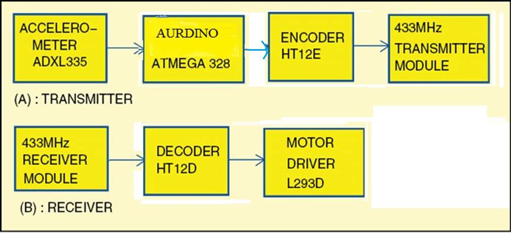
Figure 3.1 Block Diagram gesture Controlled Robot
We divided our assignment into two components to make the challenge smooth and simple and to avoid complexity and make it blunders free. The primary is the transmitting phase which includes the subsequent additives:
- Accelerometer
- Arduino Uno
- Encoder IC
- RF Transmitter Module
The second is the receiving end which comprises of following main components:
- RF Receiver Module
- Decoder IC
- Motor Driver IC
- DC Geared Motors
3.1 ACCELEROMETER (ADXL335)
An Accelerometer is an electromechanical device that measures acceleration forces. those forces can be static, just like the steady force of gravity pulling at your feet, or they can be dynamic – resulting from transferring or vibrating the accelerometer.
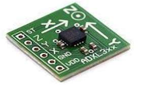
Figure 3.2 ADXL335 Accelerometer
It’s miles a form of sensor which document acceleration and offers an analog data whilst shifting in X,Y,Z path or may be X,Y route most effective relying at the type of the sensor.
PIN DESCRIPTION
| PIN NO. | SYMBOL | FUNCTION |
| 1 | ST | Sets the sensitivity of the accelerometer |
| 2 | Z | data analog statistics for Z direction |
| 3 | Y | data analog statistics for Y route |
| 4 | X | data analog statistics for X route |
| 5 | GND | Connected to ground for biasing |
| 6 | VCC | +3.3 volt is applied |
Table 3-1 Pin description for Accelerometer
3.2 ARDUINO UNO
Arduino is a tool for making computers that can sense and control more of the physical world than your desktop computer. It’s an open-source physical computing platform based on a simple microcontroller board, and a development environment for writing software for the board.
Arduino can be used to increase interactive gadgets, taking inputs from an expansion of switches or sensors, and controlling a variety of lighting fixtures, automobiles, and different physical outputs. Arduino tasks may be stand-by myself, or they can be communicating with software running on your computer. The forums may be assembled by using hand or bought preassembled; the open-supply ide can be downloaded for free. The arduino programming language is an implementation of wiring, a comparable physical computing platform, that is primarily based on the processing multimedia programming environment.
What is Arduino?
Arduino is an open source electronics platform accompanied with a hardware and software to design, develop and test complex electronics prototypes and products. The hardware includes a microcontroller with different digital additives which can be programmed the usage of the software program to do almost any mission. The simplicity of the arduino language makes it very easy for almost every body who has an interest in electronics to jot down packages with out the know-how of complicated algorithms or codes.
Arduino is intended for an artist, tinker, designer or anyone, interested in playing with electronics without the knowhow of complex electronics and programming skills. Arduino is an excellent designed open source platform. It has specially designed boards which can be programmed using the Arduino Programming Language (APL).
The presence of arduino is not simplest spreading between hobbyists, but it has additionally improved its roots in industries and utilized by specialists for making prototypes of commercial merchandise. Arduino takes to the air the efforts required in complicated coding and designing hardware.
the open supply nature of arduino has been the main cause for its rapid horizontal increase. Considering it’s far an open supply task, all of the files associated with hardware and software is to be had for private or business use. The development value of the hardware may be very small as against the pricey comparable proprietary products through the commercial giants. The open source nature doesn’t require any licenses to broaden, use, redistribute or maybe promote the product. But the arduino name is change mark covered (arduino™) i.e., you’re free to promote the arduino board below every other call however as a way to sell it beneath the name “arduino” you need to take permission from the founders and comply with their first-class phrases.
the software documents which incorporates all of the supply code library also are open sourced. A consumer can alter them to make the challenge more flexible and improve its abilities. This affords a sturdy on-line network support.
Concept of Arduino
The root of Arduino goes deep down to the development of Processing Language by MIT researchers. Processing language is an open source language designed to introduce the software development environment for the artistic people without the need of deep knowledge of programming of algorithms. Processing is based on java.
In early year of 21st century, designing an electronics gadget was nearly impossible for a common man. The requirement of specific skill set and hefty prices of software and hardware created a full stop in the path of their creativity.
In year 2003 hernando barragan, a programmer evolved an open supply electronics development platform with software program ide, wherein all people with a small knowledge in electronics and programming should use his undertaking to give wings to their creativity. His attention was to lessen the burden of complexity in designing electronics hardware and software. The challenge turned into named as wiring. The software program ide of the wiring used processing language to write down the codes because the software written in c,c++ is called as venture, within the identical manner the code written in wiring (even in processing and arduino) is called as sketch. The name sketch gives a familiar search for an artist.
The principle idea behind wiring is that possible make the comic strip of their concept on wiring software and implement it the usage of specially designed wiring board. You want to jot down a few traces of codes at the software ide and then download this system to the onboard microcontroller to see the output.
Wiring has predefined libraries to make the programming language easy. Arduino uses those libraries. The predefined libraries are written in c and c++. One may even write his software in cc++ and use them on wiring boards. The distinction among writing a application in c/c++ and wiring is that the wiring application programmable interface (api) has simplified programming style and the person doesn’t require detailed knowledge of the principles like classes, gadgets, guidelines, and so on. At the same time as sketching hardware you need to name the predefined capabilities and rest might be treated by the wiring software.
the primary distinction between the processing and the wiring is that the processing is locate to jot down this system which may be used on different computer systems at the same time as wiring software is used on microcontrollers.
History
Wiring is the predecessor of Arduino. Arduino became advanced in lvrea, Italy by Massimo Banzi and David Cuartielles in year 2005. The assignment become named after Arduin of lvrea (King of Italy). The challenge Arduino uses the Wiring language. The concept of Wiring Language changed into created via Hernando Barragan, and under his supervision Massimo Banzi and David Cuartielles developed the project Arduino.
Open Source License
Arduino is an open supply venture which might be the basis reason cause for its popularity. Arduino hardware layout is an Open source hardware, dispensed below creative common Attribution share-Alike license. creative commonplace, a non-worthwhile organization has released numerous copyleft-licenses as freed from charge, in order that the creativity/ understanding may be shared to the rest of the arena whilst having the copyright to the legal person. The at first designed files, like format and schematics of Arduino merchandise are to be had as Eagle CAD files.
The source code for its IDE and libraries are also available and released underneath GUN standard Public License (known as GPL). The GPL is the primary copyleft license for preferred use. The license is granted for the software to make sure the copyleft freedom.
Atmel Atmega328P
The ATmega328P chip is used in this project as the microcontroller. The significance of the first two digits is to stipulate that the AVR core consists of variety of instruction set with 32 general purpose working registers which are connected directly to the Arithmetic Logical Unit (ALU), tolerating two independent registers to be retrieved in one single instruction executed in one clock cycle. The subsequent architecture is more programmable efficient while attaining data transfer rates up to ten times quicker than other CISC microcontrollers. The last digit is to indicate the 8 bit bi-directional port. It is certainly the head of the system which is controlling the various modules. The AVR is a modified Harvard architecture 8-bit RISC single chip microcontroller which was developed by Atmel in 1996. The AVR was one of the first microcontroller families to use on-chip flash memory for program storage, as opposed to one-time programmable ROM, EPROM, or EEPROM used by other microcontrollers at the time.
The Arduino hardware was very skilfully designed to reduce the complexities arising in the circuitry. It has an In System Programmer (ISP), which allows users to transfer the software inside the microcontroller without removing it from the circuit. The basic model of an Arduino board consists of an 8-bit AVR microcontroller along with some other necessary components like a 5 volt linear regulator IC, a 16 MHZ crystal, ceramic resonator, output connectors, direct adaptor input, etc.
The IO ports on boards are positioned in a way that it can be easily attached with the interchangeable add-on modules, known as shields. Shields are daughter boards that can be externally attached/ plugged with the Arduino boards to extent the board’s capabilities. For example an xbee shield can be attached with the Arduino board to establish a wireless communication. A motor control shield can be attached on the top of Arduino board to run the motors or to provide an ease to control the speed of motors. The Arduino Board can easily interface with external sensors, circuits or other peripherals.
Arduino hardware is available in various designs and configurations depending on the use. The different configurations use different AVR chips, Atmega8/168/328/1280/2560. Each board has its own additional feature, like Arduino UNO consists of ATmega328 which communicates to PC via USB using FTDI chip. very comfortable for attaching shields. On the other Arduino NANO uses Atmega168/328 which also uses FTDI chip but is much comfortable to use it on breadboard.
Some non-ATmega Arduino boards are also available. These boards don’t contain Atmel’s ATmega controller but are compatible with Arduino shield. These microcontrollers cannot be programmed by the standard Arduino IDE but manufacturers do provide some other versions of Arduino IDE which includes the necessary libraries related to the controller. For example Leaflabs Maple based on 32bit arm processor or chip KIT UNO32 based on PIC micro controllers.
The earlier version of the Arduino board had controller with bootloader which communicated with the Arduino IDE mostly via a Serial port. Later a FTDI chip was introduced on the Arduino board which is a USB to serial converter to allow the communication with the USB port. And today the Arduino boards are available with Atmel’s microcontroller which have inbuilt capacity to communicate with the USB port.
The high-performance Atmel Pico Power 8-bit AVR RISC-based microcontroller combines 32KB ISP flash memory with read-while-write capabilities, 1024B EEPROM, 2KB SRAM, 23 general purpose I/O lines, 32 general purpose working registers, three flexible timer/counters with compare modes, internal and external interrupts, serial programmable USART, a byte-oriented 2-wire serial interface, SPI serial port, a 6-channel 10-bit A/D converter (8-channels in TQFP and QFN/MLF packages), programmable watchdog timer with internal oscillator, and five software selectable power saving modes. The device operates between 1.8-5.5 volts. By executing powerful instructions in a single clock cycle, the device achieves throughputs approaching 1 MIPS per MHz, balancing power consumption and processing speed (Atmel Corporation).
Arduino UNO
To program the ATmega328P Microcontroller a Serial communicator is required. Serial communication is most widespread interface between microcontroller and computer. UART is one of the serial interfaces which are widely used. A Universal Asynchronous Receiver/Transmitter (UART) is a piece of computer hardware that translates data between parallel and serial forms. Classically, most serial interface from microcontroller to computer is done through serial port (DB9).
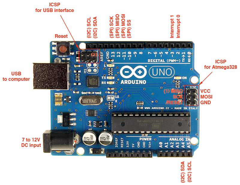
Figure 3.3 Arduino Uno
However, since computer serial port used RS232 protocol and microcontroller used TTL UART, a level shifter is needed between these interfaces. There are several level shifters available in the market, some of which supports USB plug and play.
But in most of the times the level shifter are unstable to use due to its design and more than one software is required to convert the programming on C to hex or machine language and maybe another software to interface between the Microcontroller and computer.
Arduino UNO is an alternative to this solution, the internal board of Arduino consists of all the necessary ICs for communication. It is also build compact into a PCB which has connectors for fast and easy prototyping.
Summary
- Microcontroller ATmega328
- running Voltage 5V
- input Voltage (encouraged) 7-12V
- input Voltage (limits) 6-20V
- digital I/O Pins 14 (of which 6 provide PWM output)
- Analog enter Pins 6
- DC modern in step with I/O Pin forty mA
- DC contemporary for three.3V Pin 50 mA
- Flash reminiscence 32 KB (ATmega328) of which 0.5 KB used by bootloader
- SRAM 2 KB (ATmega328)
- EEPROM 1 KB (ATmega328)
- Clock velocity 16 MHz
Pin Configuration
The Arduino Uno can be powered via the USB connection or with an outside power supply. The strength supply is chosen routinely. outside (non-USB) power can come both from an AC-to-DC adapter (wall-wart) or battery. The adapter can be connected with the aid of plugging a 2.1mm middle-superb plug into the board’s energy jack. Leads from a battery may be inserted in the Gnd and Vin pin headers of the energy connector.
The board can operate on an external supply of 6 to twenty volts. If furnished with much less than 7V, but, the 5V pin may also deliver much less than 5 volts and the board may be unstable. If using greater than 12V, the voltage regulator may overheat and damage the board. The advocated variety is 7 to 12 volts.
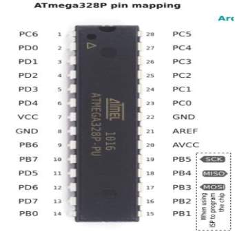
Figure 3.4 Pin Configuration
The strength pins are as follows:
VIN: The enter voltage to the Arduino board while it is using an external energy supply (as
against 5 volts from the USB connection or other regulated energy source). you can deliver voltage thru this pin, or, if presenting voltage through the power jack, get admission to it thru this pin.
5V: This pin outputs a regulated 5V from the regulator on the board. The board may be furnished with energy either from the DC energy jack (7 – 12V), the USB connector (5V), or the VIN pin of the board (7-12V). imparting voltage via the 5V or 3.3V pins bypasses the regulator, and may harm your board.
3V3: A 3.three volt deliver generated by the on-board regulator. maximum present day draw is 50 mA.
GND: floor pins.
IOREF: This pin on the Arduino board provides the voltage reference with which the microcontroller operates. A properly configured guard can examine the IOREF pin voltage and pick out the proper energy supply or enable voltage translators on the outputs for operating with the 5V or 3.3V.
Reminiscence:
The ATmega328 has 32 KB (with zero.five KB used for the boot loader). It also has 2 KB of SRAM and 1 KB of EEPROM.
ENTER AND OUTPUT:
Each of the 14 virtual pins at the Uno can be used as an enter or output, the usage of pinMode(), digital Write( ), and digital read( ) capabilities. They function at 5 volts. each pin can offer or acquire a maximum of 40 mA and has an internal pull-up resistor (disconnected by using default) of 20-50 kohms. similarly, a few pins have specialized capabilities:
SERIAL: zero (RX) and 1 (TX). Used to receive (RX) and transmit (TX) TTL serial statistics.
these pins are related to the corresponding pins of the ATmega8U2 USB-to- TTL Serial chip.
EXTERNAL INTERRUPTS: 2 and 3. those pins may be configured to trigger an interrupt on a low value, a growing or falling aspect, or a trade in price. See the attachInterrupt() feature for info.
PWM: three, five, 6, 9, 10, and 11. offer eight-bit PWM output with the analogWrite() feature.
SPI: 10 (SS), eleven (MOSI), 12 (MISO), 13 (SCK). those pins aid SPI communique using the SPI library.
LED: 13. there’s a constructed- in LED connected to virtual pin 13. when the pin is excessive price, the LED is on, while the pin is LOW, it’s off.
The Uno has 6 analog inputs, categorised A0 through A5, every of which provide 10 bits of decision (i.e. 1024 extraordinary values). by default they degree from floor to five volts, even though is it feasible to alternate the top quit in their range the use of the AREF pin and the analog Reference() feature. additionally, a few pins have specialised functionality:
TWI: A4 or SDA pin and A5 or SCL pin. aid TWI conversation the usage of the twine library.
There are multiple different pins on the board:
AREF. Reference voltage for the analog inputs. Used with analogReference().
RESET. deliver this line LOW to reset the microcontroller. normally used to add a reset button to shields which block the only on the board.
COMMUNICATION
Microcontrollers rely upon a number laptop for growing and compiling packages. The software used at the host pc is known as an incorporated improvement surroundings, or IDE. For the Arduino, the development surroundings is based totally on the open supply Processing platform (www.processing.org) that’s defined by means of its creators as a “programming language and surroundings for folks that want to software images, animation, and interactions.
The Arduino programming language leverages an open supply mission referred to as Wiring (wiring.org.co). The Arduino language is based totally on top antique- common C. in case you are unfamiliar with this language, don’t worry; it’s not hard to learn, and the Arduino IDE affords some remarks whilst you make mistakes for your applications.
The Arduino Uno has some of facilities for speaking with a pc, any other Arduino or other microcontrollers. The ATmega328 affords UART TTL (5V) serial communique, which is to be had on virtual pins zero (RX) and 1 (TX). An ATmega16U2 at the board channels this serial communication over USB and appears as a digital com port to software program on the pc. The ’16U2 firmware uses the usual USB COM drivers, and no outside driving force is needed. however, on home windows, a info file is needed. The Arduino software program consists of a serial display which allows simple textual statistics to be despatched to and from the Arduino board. The RX and TX LEDs at the board will flash when facts is being transmitted thru the USB-to-serial chip and USB connection to the laptop (but no longer for serial conversation on pins zero and 1).
A software Serial library allows for serial communication on any of the Uno’s virtual pins. The ATmega328 also helps I2C (TWI) and SPI verbal exchange. The Arduino software includes a wire library to simplify use of the I2C bus; see the documentation for information. For SPI conversation, use the SPI library.
As you go through the listing of programming statements available inside the Arduino IDE (pick help->Reference), you would possibly suppose there isn’t a lot power for doing such things as going for walks servos, running stepper automobiles, analyzing potentiometers, or displaying text on an liquid crystal display. Like maximum any language based on C, the Arduino supports the notion of “libraries” code repositories that amplify middle programming capability. Libraries can help you re-use code without having to bodily copy and paste it into all your applications.
3.3 ENCODER IC (HT12E)
HT12E is an encoder incorporated circuit of 212 series of encoders. they may be paired with 212 series of decoders to be used in remote manage gadget applications. it is especially used in interfacing RF and infrared circuits.
The chosen pair of encoder/decoder must have equal quantity of addresses and facts format. really placed, HT12E converts the parallel inputs into serial output. It encodes the 12 bit parallel records into serial for transmission thru an RF transmitter. those 12 bits are divided into eight deal with bits and four information bits.
HT12E has a transmission enable pin which is lively low. whilst a trigger signal is acquired on TE pin, the programmed addresses/information are transmitted collectively with the header bits through an RF or an infrared transmission medium.
PIN DIAGRAM
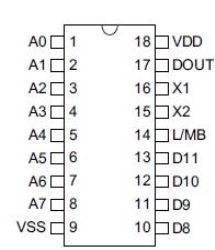
Figure 3.5 HT12E IC
PIN DESCRIPTION
| PIN NO. | SYMBOL | FUNCTION |
| 1-8 | A0-A7 | Address pins |
| 9 | Vss | Ground pin |
| 13-10 | D0-D3 | Output pins |
| 14 | TE | Enables the transmission |
| 15-16 | Osc1-Osc2 | Rosc of 470K ohm is connected |
| 17 | Dout | Output for transmission |
| 18 | Vcc | 5V supply voltage |
Table 3.2 Pin description for HT12E
HT12E starts offevolved a four-phrase transmission cycle upon receipt of a transmission enable. This cycle is repeated so long as TE is kept low. As quickly as TE returns to high, the encoder output completes its very last cycle after which stops.
3.4 RF MODULE (Rx/Tx)
Radio frequency (RF) is a rate of oscillation within the range of about three KHz to three hundred GHz, which corresponds to the frequency of radio waves, and the alternating currents which carry radio signals.
Although radio frequency is a price of oscillation, the term “radio frequency” or its abbreviation “RF” also are used as a synonym for radio – i.e. to describe using wireless verbal exchange, in preference to verbal exchange thru electric powered wires.
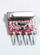
| Figure 3.6 RF Transmitter | ||||||||||||||||
|
The RF module is operating at the frequency of 315 MHz and has a range of 50 -eighty meters. PIN DESCRIPTION |
||||||||||||||||
|
Table 3.3 RF Transmitter
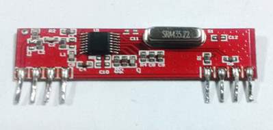
Figure 3.7 RF Receiver
PIN DESCRIPTION
| Pin Number | Function | Name |
| 1 | Ground (0V) | GND |
| 2 | Serial Data Output Pin | DATA |
| 3 | Linear Output Pin; Not Connected | NC |
| 4 | Supply Voltage (5V) | VCC |
| 5 | Supply Voltage (5V) | VCC |
| 6 | Ground (0V) | GND |
| 7 | Ground (0V) | GND |
| 8 | Antenna Input Pin | ANT |
Table 3.4 RF Receiver
3.5 DECODER IC (HT12D)
HT12D IC comes from HolTek employer. HT12D is a decoder incorporated circuit that belongs to 212 series of decoders. This collection of decoders are in particular used for remote manage device programs, like burglar alarm, car door controller, protection machine and many others. it is particularly supplied to interface RF and infrared circuits. they are paired with 212 collection of encoders. the selected pair of encoder/decoder should have identical number of addresses and records format.
In simple terms, HT12D converts the serial input into parallel outputs. It decodes the serial addresses and statistics received by means of, say, an RF receiver, into parallel information and sends them to output statistics pins. The serial enter information is in comparison with the nearby addresses three instances continuously. The enter facts code is decoded whilst no error or unmatched codes are found. A valid transmission in indicated through a high sign at VT pin.
HT12D is capable of interpreting 12 bits, of which eight are deal with bits and 4 are information bits. The facts on 4 bit latch type output pins remain unchanged till new is obtained.
PIN DIAGRAM
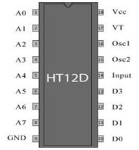
Figure 3.8 HT12D IC
PIN DESCRIPTION
| PIN NO. | SYMBOL | FUNCTION |
| 1-8 | A0-A7 | Address pins |
| 9 | Vss | Ground pin |
| 13-10 | D0-D3 | Output pins |
| 14 | Din | Input from RF |
| 15-16 | Osc1-Osc2 | Rosc of 470K ohm is connected |
| 17 | VT | Indicates valid transmission |
| 18 | Vcc | 5V supply voltage |
| Table 3.5 Pin description for HT12D | ||
3.6 MOTOR DRIVER IC (L293D)
It’s also known as h-bridge or actuator ic. Actuators are those devices which actually gives the motion to do a challenge like that of a motor. In the actual world there are specific styles of cars available which works on special voltages. So we need a motor driver for going for walks them through the controller.
The output from the microcontroller is a low current signal. The motor driver amplifies that current that can manage and drive a motor. In most instances, a transistor can act as a switch and carry out this undertaking which drives the motor in a single path so known as h-bridge or actuator ic. Actuators are those devices which actually gives the motion to do a challenge like that of a motor. In the actual world there are specific styles of cars available which paintings on special voltages. So we need a motor driver for going for running them through the controller.
PIN DIAGRAM
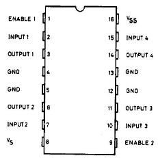
Figure 3.9 L293D IC
Turning a motor on and off requires most effective one transfer to govern a single motor in a single path. We can opposite the course of the motor by way of surely reversing its polarity.
This could be done by way of the usage of 4 switches which can be organized in an smart manner such that the circuit not only drives the motor, however also controls its course. Out of many, one of the most common and clever layout is a h-bridge circuit in which transistors are organized in a shape that resembles the english alphabet “h”.
As seen inside the picture, the circuit has four switches a, b, c and d. Turning those switches on and off can pressure a motor in distinct ways.
- When switches A and D are on, motor rotates clockwise.
- While A and C are on, the motor rotates anti-clockwise.
- While A and B are on, the motor will stop.
- Turning off all the switches offers the motor a free wheel power.
- Turning on A & C on the same time or B & D at the identical time shorts the whole circuit. so, never try to do it.
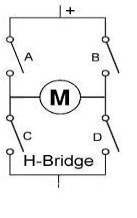
Figure 3.10 h-bridge
3.7 DC MOTORS
A device that converts DC strength into mechanical power is called a DC motor. Its operation is based on the principle that when a current carrying conductor is positioned in a magnetic discipline, the conductor stories a mechanical force.
DC motors have a revolving armature winding but non-revolving armature magnetic subject and a desk bound field winding or permanent magnet. extraordinary connections of the sphere and armature winding offer exclusive velocity/torque law capabilities. the speed of a DC motor can be managed by way of converting the voltage implemented to the armature or by means of converting the sphere contemporary.
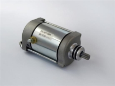
Figure 3.11 DC Motor
3.7.1 DC GEAR MOTOR
A geared DC Motor has a gear meeting committed to the motor. The rate of motor is counted in phrases of rotations of the shaft in keeping with minute and is termed as RPM .The equipment meeting facilitates in increasing the torque and dropping the rate. the use of the perfect arrangement of gears in a equipment motor, its speed can be reduced to any required determine. This concept of decreasing the rate with the assist of gears and growing the torque is called gear discount.
Reducing the speed positioned out by way of the motor whilst increasing the quantity of applied torque is a critical feature of the discount gear trains observed in a tools motor. The lower in pace is inversely relative to the increase in torque. This affiliation approach that, on this sort of device, if the torque were to double, the rate might decrease by way of one 1/2. Small electric powered motors, along with the equipment motor, are capable of flow and stand very heavy masses due to those discount equipment trains. whilst the velocity and capacity of large vehicles is greater, small electric automobiles are enough to endure those loads.
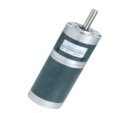
Figure 3.12 DC Gear Motor
CHAPTER 4: SOFTWARE DESCRIPTION
4.1 AURDINO IDE
The Arduino incorporated improvement environment (IDE) is a go-platform utility written in Java, and is derived from the IDE for the Processing programming language and the Wiring projects. It includes a code editor that’s capable of compiling and importing programs to the board with a single click A program or code written for Arduino is called a “sketch”.
Following are the steps involved:
Open Arduino IDE as shown below
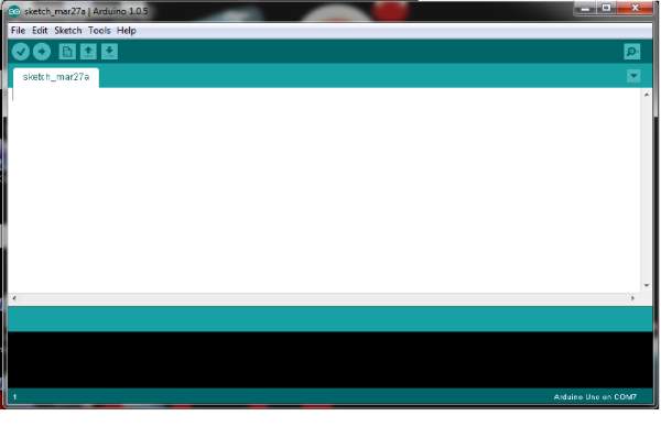
Figure 4.1 Arduino IDE
Arduino applications are written in C or C++. The Arduino IDE comes with a software library called “Wiring” from the original Wiring mission, which makes many commonplace enter/output operations plenty green. customers most effective need outline functions to make a runnable cyclic government software:
setup(): a function run once at the start of a program that can initialize settings
loop(): a function called repeatedly until the board powers off
Select the COM Port from tools
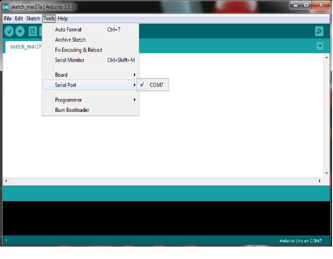
Figure 4.2 Arduino IDE Select COM
Select the required Arduino board from Tools
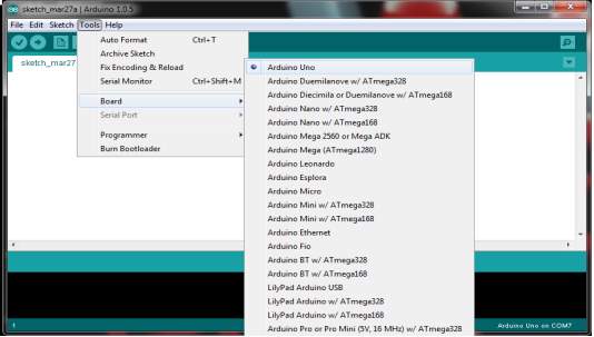
Figure 4.3 Arduino IDE Selection of Board
Write the sketch in Arduino IDE
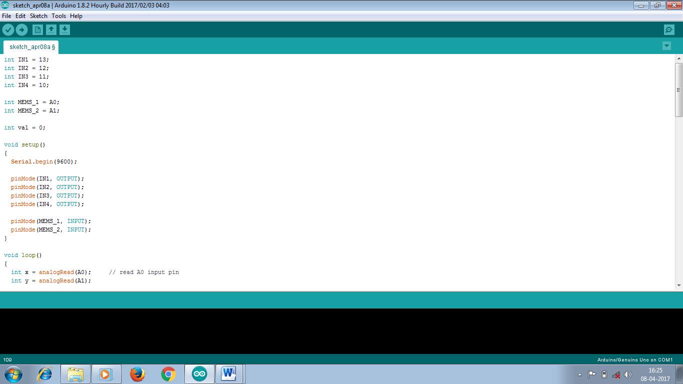
Figure 4.4 Arduino IDE sketch
Compile and upload the Sketch to Arduino board
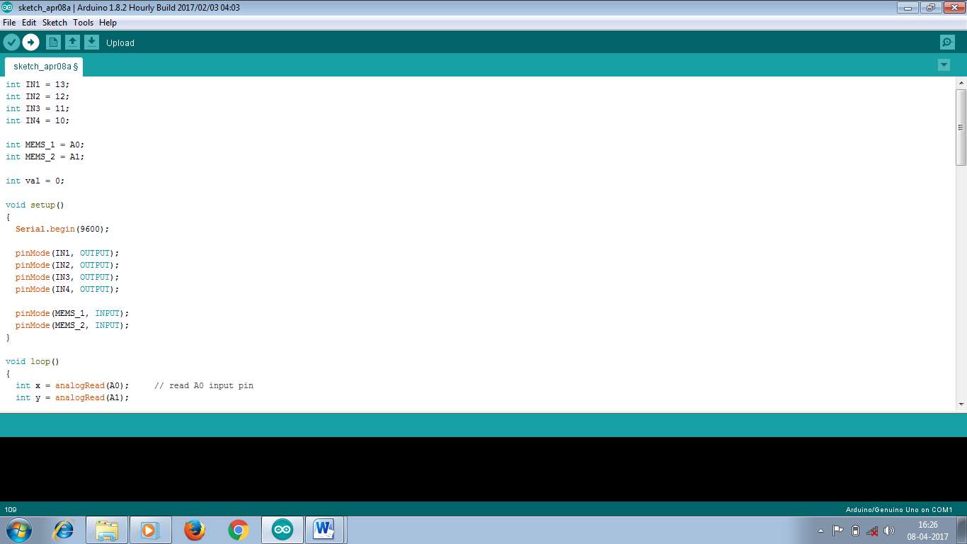
Figure 4.5 Arduino IDE Compile and Upload
4.2 FLOWCHART
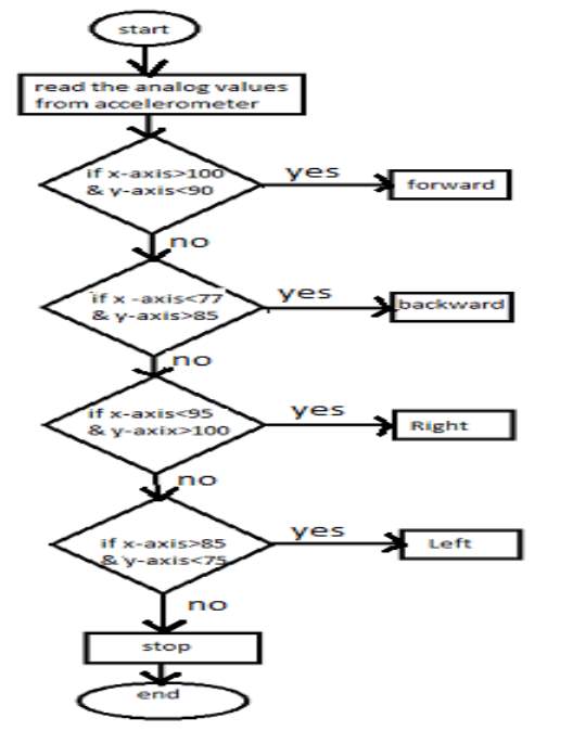
Figure 4.6 Flow Chart
CHAPTER 5: DESIGN AND WORKING PRINCIPLE
5.1 CIRCUIT DESIGN OF HAND GESTURE CONTROL ROBOT
TRANSMITTER SECTION
The transmitter phase of the robotic consists of Arduino Uno board, three-Axis Accelerometer Sensor, HT-12E Encoder and an RF Transmitter.
As it’s far a easy robot moving in one of a kind directions, facts from handiest 2 of the three axis is being captured. The Accelerometer sensor has 6 pins viz. Vcc, Gnd, Xout, Yout, Zout and ST.
Xout, Yout and Zout are the analog outputs of the three-axis accelerometer corresponding to X-axis, Y-axis and Z-axis respectively.
ST is the sensitivity adjusting pin. Vcc and Gnd are connected to electricity rails. Zout and ST are left open. The Xout and Yout pins are linked to the analog in pins of the Arduino (A0 and A1).
HT-12E is an encoder IC often associated with RF Transmitter module. It converts the 12-bit parallel information to serial information.
The 12-bit data is divided into address and data bits. A0 to A7 (Pin 1 to Pin8) are the address bits and they are used for secure transmission of the data.
Those pins may be both left open or connected to ground (Vss). in this circuit, Pin 1 to Pin 9 (A0 – A7 and Vss) of HT-12E are linked to ground.
Pins 10 to 13 (AD8, AD9, AD10 and AD11) are the information pins of HT-12E. They obtain the four word parallel facts from outside supply like a microcontroller (Arduino in this case).they are linked to the pins three, five, 7 and 8 of Arduino respectively. TE’ is the transmission allow pin and it is an lively low pin. The information is transmitted so long as the TE’ is low. Consequently, Pin 14 (TE’) is also related to floor. The encoder IC has an inner oscillator circuit among the pins 16 and 15 (OSC1 and OSC2). A 1MΩ resistor is attached among these pins to enable the oscillator. Dout (Pin 17) is the serial facts out pin. it’s far related to the facts in pin of the RF Transmitter.
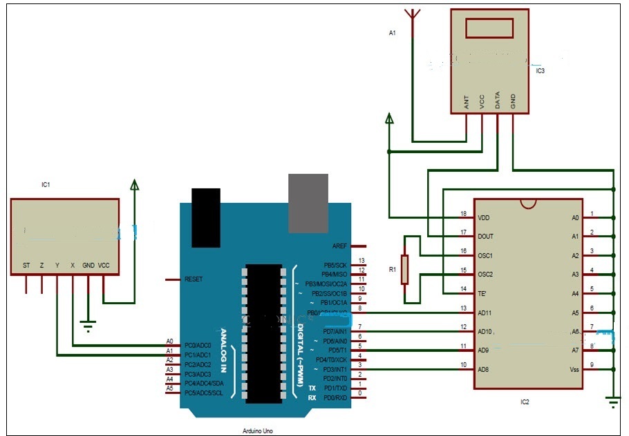
Figure 5.1 Schematic Diagram of Transmitter Section
RECEIVER SECTION
The receiver section of the robot consists of an RF receiver, ht-12d decoder ic, l293d motor driver ic and a robotic chassis with two motors connected to wheels.
Ht-12d is the decoder ic regularly related to RF receiver. It converts the serial data obtained by means of the RF hyperlink into parallel records.
A0 to a7 (pin 1 to pin eight) are the cope with pins and must be matched with the address pins of the encoder.
Because the address pins of encoder (ht-12e) are grounded, the address pins of decoder need to also be grounded. Consequently, pins 1 to nine (a0 – a7 and vss) are connected to floor. Pins 10 to 13 (d8, d9, d10 and d11) are the parallel facts out pins.
They may be connected to the input pins of the l293d motor driver ic (pins 2, 7, 10 and 15 respectively). The serial records from the RF receiver is given to din (pin 14) of the decoder ic.
Ht-12d has an internal oscillator and an outside resistor of 51k is connected between osc1 and osc2 (pins 16 and 15).
Pin 17 (VT) indicates a valid transmission of data and this pin will be high when a valid data is present on the data pins. An LED in series with a resistor is connected to this pin to indicate a valid data transmission..
L293d motor driving force ic is used to provide the important cutting-edge (for each forward and opposite instructions) to the motors. Pins 1 and 9 are the allow pins and are connected to vcc. Pins 3 – 6 and eleven – 14 are the outputs and are connected to the automobiles.
The receiver phase of the robot consists of an RF Receiver, HT-12D Decoder IC, L293D Motor driver IC and a robotic chassis with two vehicles connected to wheels.
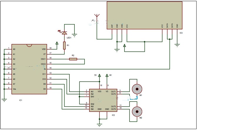
Figure 5.2 Schematic Diagram of Receiver Section
5.2 WORKING OF HAND GESTURE CONTROLLED ROBOT
In this assignment, a mobile robotic this is controlled by way of the gestures made via the hand is designed. The operating of the robotic is defined here.
As stated in advance, the gesture managed robotic is a wireless operated robotic and has elements: transmitter and receiver.
When the robotic is powered on, the transmitter element, which includes arduino, accelerometer, encoder and RF transmitter, will continuously monitor the accelerometer sensor.
This information is captured by the arduino, which transmits suitable information to the encoder, based on the orientation of the accelerometer.the parallel statistics obtained by way of the encoder is transformed into serial records and this serial facts is transmitted by using the RF transmitter.
At the receiver phase, the RF receiver receives the serial records and transmits to decoder ic.
The decoder will convert the serial records to parallel records and this parallel information is given to the motor driver ic. Based totally on the information, the movement of the vehicles, and hence the motion of the robotic is described.
The transmitter prototype is stored on the palm and the receiver prototype ( i.e robot) actions according to the palm motion. This paper explains approximately the 5 one of a kind gesture position of the hand i. i.e stop condition, forward movement, backward movement, moves towards right and moves towards left.
Stop Condition
When the accelerometer is parallel to the horizontal plane, all the output pins of decoder (13, 12, 11, 10) are set to high which makes the robot in stop mode Since all the output pins are high as shown in figure.

Figure 5.3 Stop Condition
Forward Movement
When the accelerometer is tilted to forward, two output pin of decoder (13, 11) are set to low and other two output pin of decoder (12, 10) are set to high. This condition commands the robot to move in forward direction pin 10 and 12 are high, as shown in figure
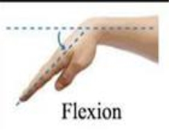
Figure 5.4 Forward Movement
Backward Movement
When the accelerometer is tilted towards backward direction, two output pin of decoder (12, 10) are set to low and other two output pin of decoder (13, 11) are set to high. This condition commands the robot to move in backward direction pin 10 and 12 are low as shown in figure.
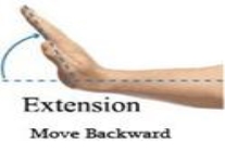
Figure 5.5 Backward Movement
Moves Towards Right
When the accelerometer is tilted towards right, two output pin of decoder (12, 11) are set to low and other two output pin of decoder (13, 10) are set to high. This condition commands the robot to move towards right pin 11 and 12 are low as shown in figure
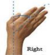
Figure 5.6 Moves Towards Right
Moves Towards Left
When the accelerometer is tilted towards left, two output pin of decoder (12, 11) are set to high and other two output pin of decoder (13, 10) are set to low. This condition commands the robot to move towards left pin 11 and 12 are glowing since, as shown in figure.
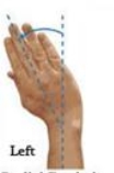
Figure 5.7 Moves Towards Left
CHAPTER 6: RESULT AND ANALYSIS
We completed our goal with none hurdles i.e. the control of a robotic the usage of gestures. The robot is displaying right responses every time we move our hand. specific Hand gestures to make the robot pass in precise directions are as comply with:
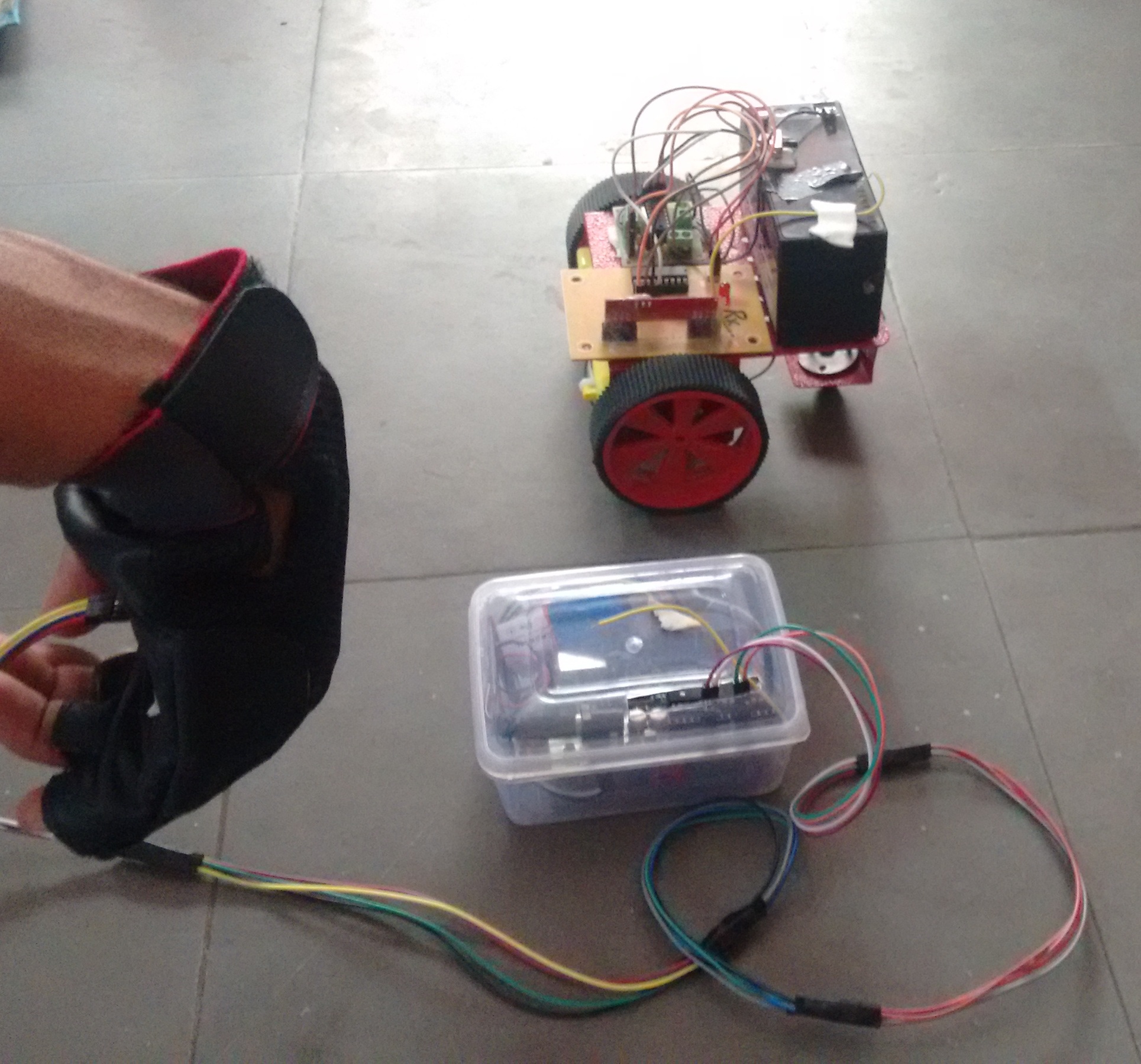
Figure 6.1 Move Forward

Figure 6.2 Move Backward
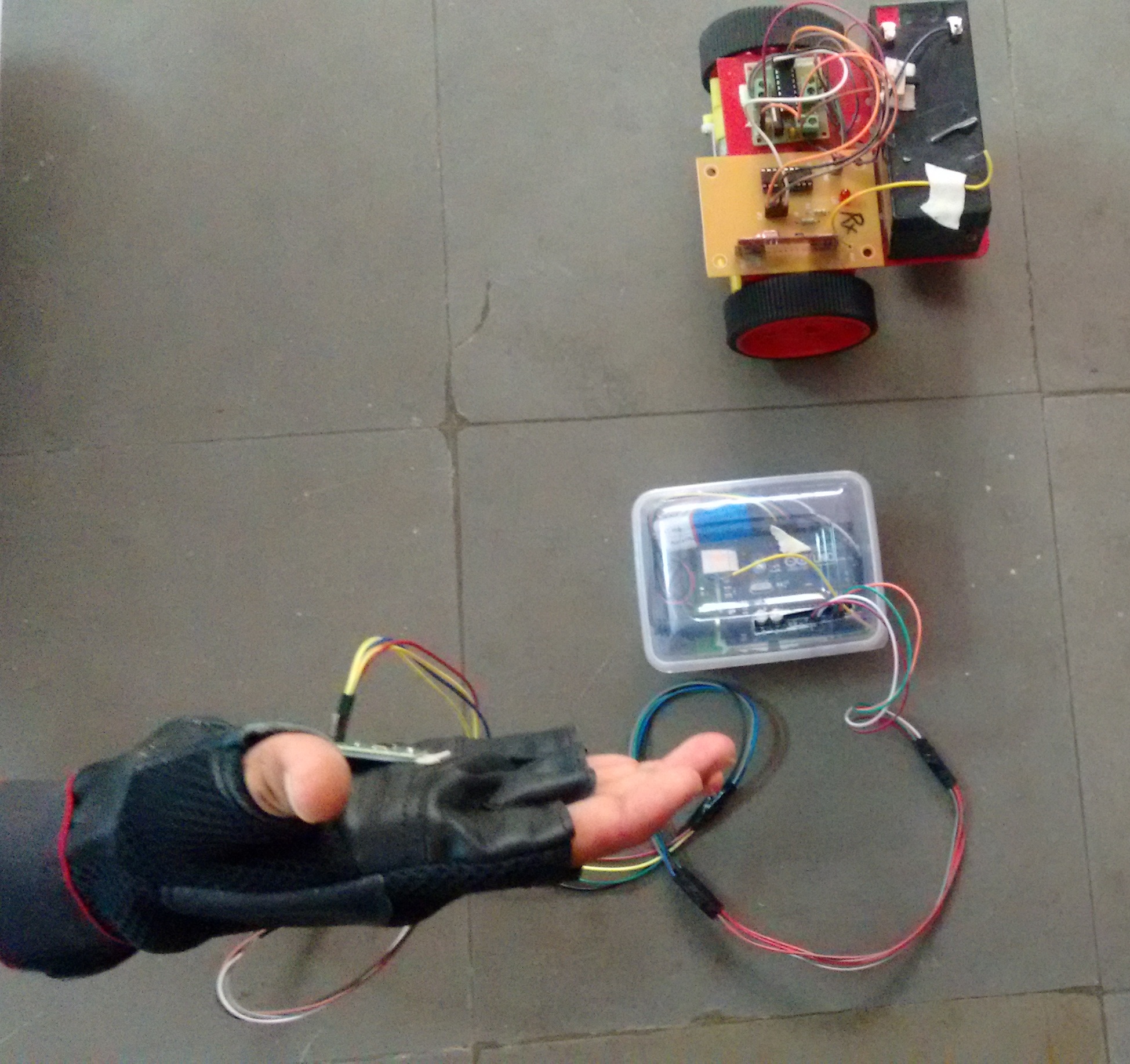
Figure 6.3 Move Right
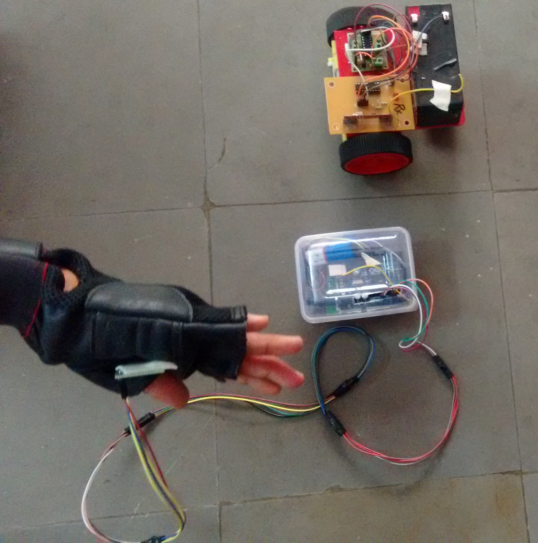
Figure 6.4 Move Left
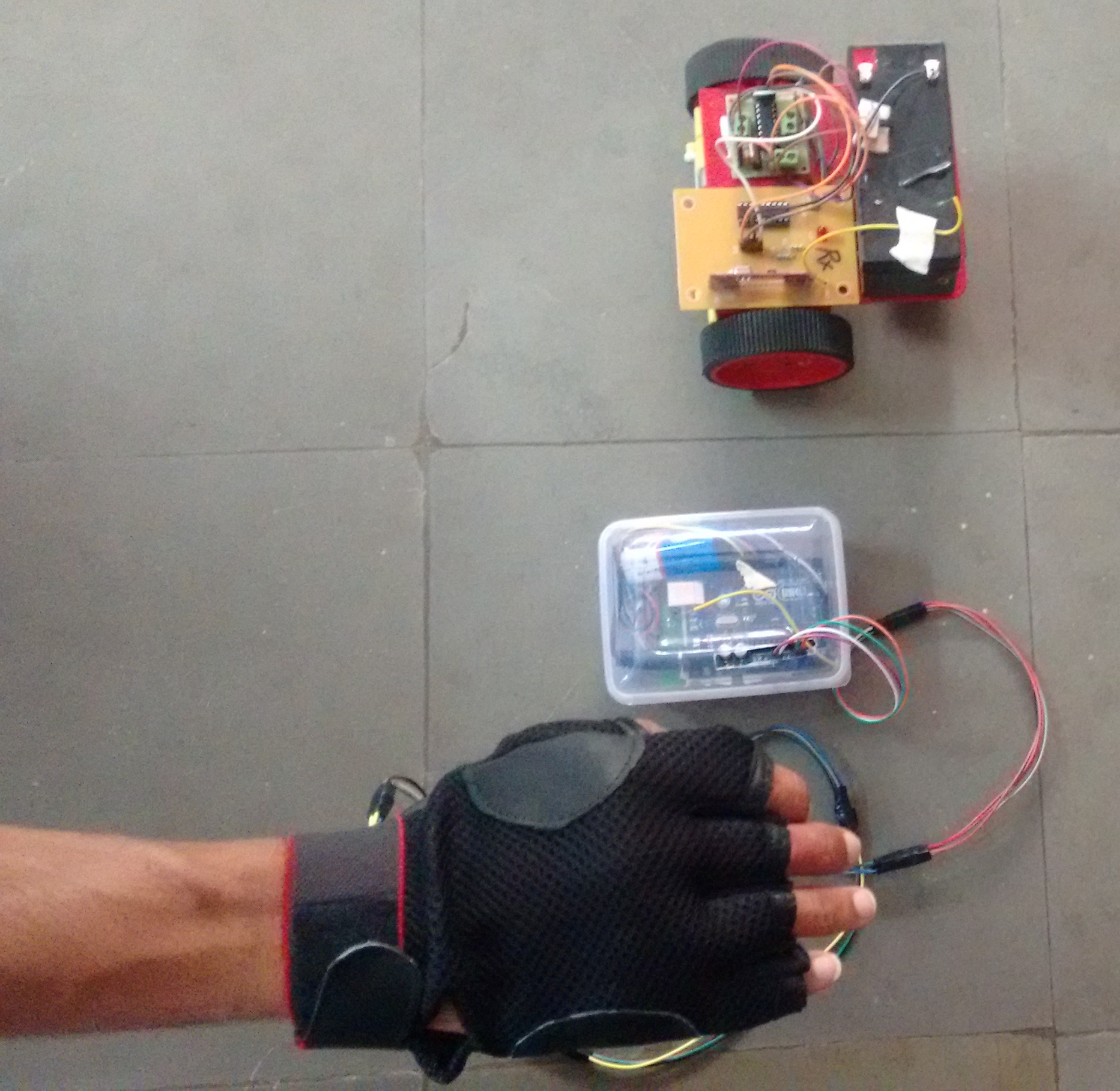
Figure 6.5 Stop Condition
The robot only moves when the accelerometer is moved in a specific direction. The valid movements are as follows:
| DIRECTION | ACCELEROMETER ORIENTATION |
| Forward | +y |
| Backward | -y |
| Right | +x |
| Left | -x |
| Stop | Rest |
Table 6.1 Accelerometer Orientation
Our finished product can be seen in the images below:
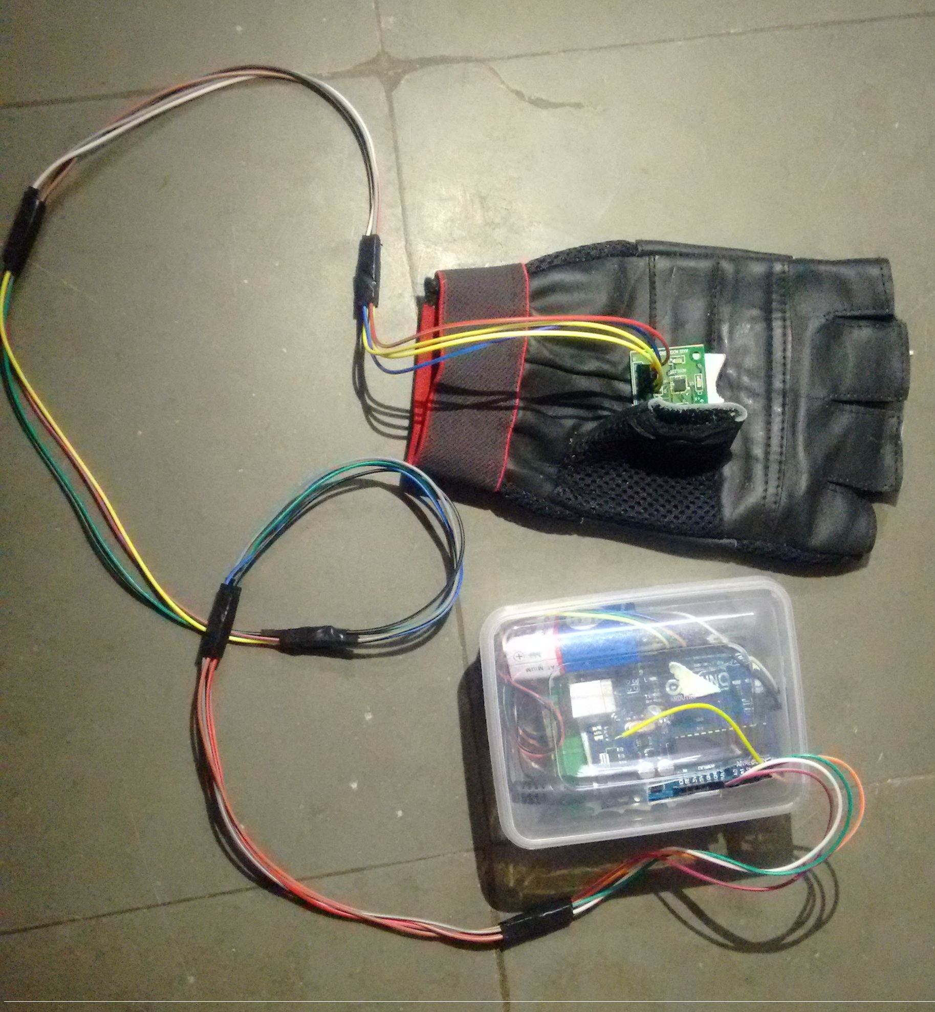
Figure 6.5 Transmitter Section
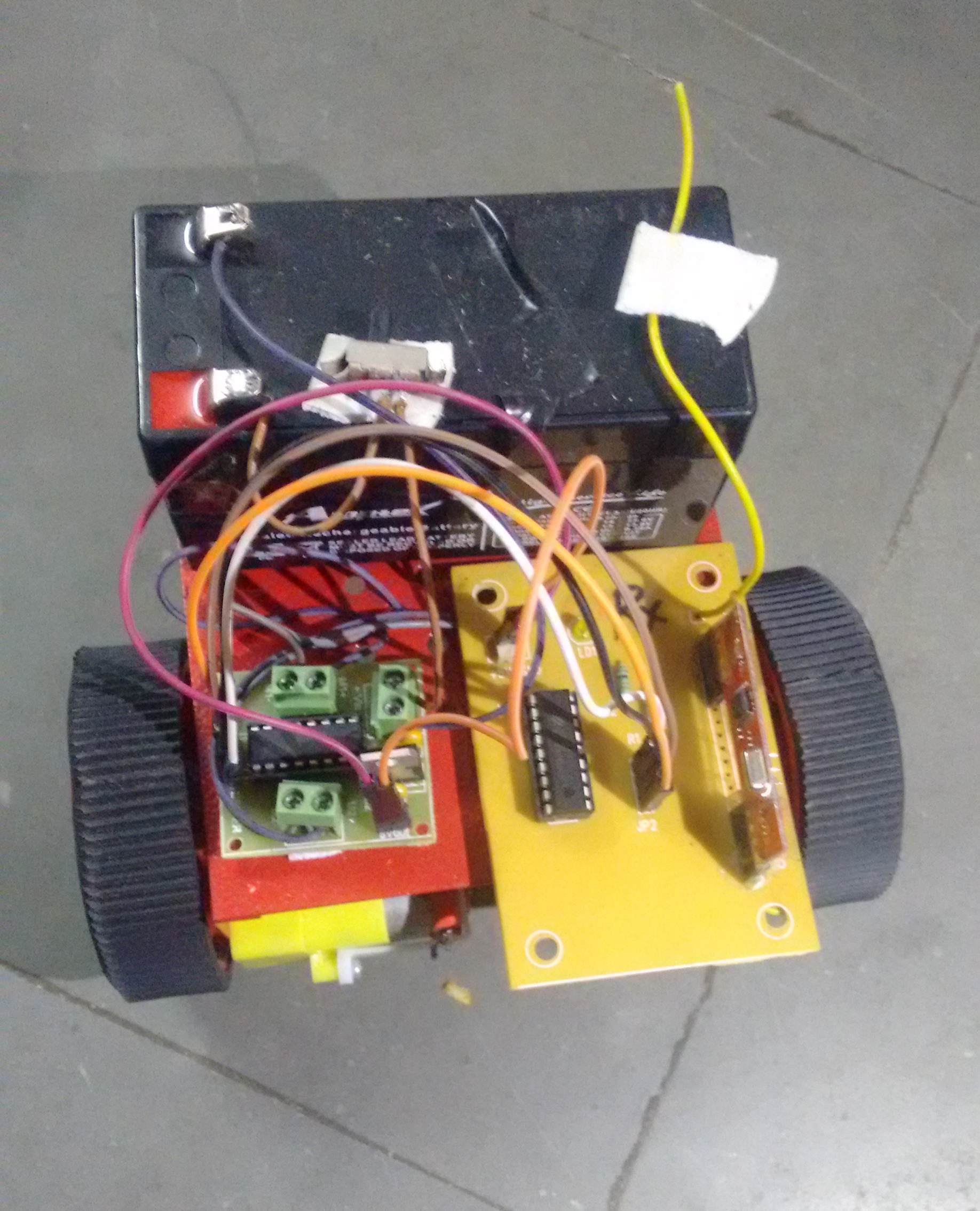
Figure 6.5 Receiver Section
CHAPTER 7: FEASIBILITY OF PROJECT
7.1 CONCLUSION
Hand Gesture Control becomes an example of companionship between man and machine in the race of man vs. Machine further enhancing the technology to the next level from Speech recognitions and wired connections to wireless hand gesture control technology. There is a rapid growth on application development considering gesture recognition system. So in this paper, we propose a model of a robot based on “Human Gesture Recognition” utilizing hand gestures to communicate with the robot. The 3- axis accelerometer selected to be the input device of this system captures the human gestures. When compared with the other input devices accelerometer is easier to work and offers the possibility to control a robot by wireless means. The low price and short set-up time are other advantages of the system but an important limitation to consider is the reliability of the system Physical hardship to the user is avoided through the use of accelerometer as with the twist of the hand, the user gets the ability and freedom to turn the robot into the desired direction.
7.2 FUTURE WORK
Future work will build upon the improvement of the correctly recognized the gestures. One approach might be the implementation of a gyroscope into the system, in order to separate the acceleration due to gravity from the inertial acceleration and second approach can be that we can install a GPS in the system to track the position of robot. The use of more accelerometers attached to the arms is another possibility.
An on-board camera can be installed for monitoring the robot from faraway places. All we need is a wireless camera which has to be placed on board will broadcast and a receiver module which will provide live streaming.
7.4 LIMITATIONS
The On-board batteries occupy a whole lot of area and are also pretty heavy. We both use some alternate strength supply for the batteries or replace the modern DC motors with ones which require less strength.
As we’re the usage of for wirelsss transmission , the variety is pretty restrained ; nearly 50-80m. This trouble can be solved via utilizing a GSM module for wi-fi transmission. The GSM infrastructure is installed almost everywhere in the international. GSM will now not only offer wireless connectivity but additionally pretty a big range.
7.5 REFERENCES
Electronic Circuit & Device Millmen& Halkias.
Grob Basic Electronics & Linear Circuit N.N.Bhargava D.C.Kulsreshtha S.C.Gupta
Arduino Cookbook, 2nd Edition by Michael Margolis.
< http://www.robotplatform.com/howto/L293/motor_driver_1.html>
< http://www.wisegeek.com/what-is-a-gear-motor.htm >
7.6 ANNEXURE
int IN1 = 13;
int IN2 = 12;
int IN3 = 11;
int IN4 = 10;
int MEMS_1 = A0;
int MEMS_2 = A1;
int val = 0;

void setup()

{
Serial.begin(9600);
pinMode(IN1, OUTPUT);
pinMode(IN2, OUTPUT);
pinMode(IN3, OUTPUT);
pinMode(IN4, OUTPUT);
pinMode(MEMS_1, INPUT);
pinMode(MEMS_2, INPUT);
}

void loop()

{
int x = analogRead(A0);     // read A0 input pin
int y = analogRead(A1);
Serial.println(“X”);
Serial.println(x);
Serial.println(“Y”);
Serial.println(y);
delay(200);

if ((x > 325 && x < 380) && (y > 330 && y < 370))

{
stp();
}

if ((x > 340 && x < 375) && (y > 400 && y < 455))

{
fwd();
}

if ((x > 340 && x < 375) && (y > 265 && y < 300))

{
bwk();
}

if ((x > 270 && x < 310) && (y > 340 && y < 385))

{
rgt();
}

if ((x > 400 && x < 450) && (y > 335 && y < 380))

{
lft();
}

}

void fwd()

{
digitalWrite(IN1, HIGH);
digitalWrite(IN2, LOW);
digitalWrite(IN3, HIGH);
digitalWrite(IN4, LOW);
Serial.println(“FORWARD”);
}

void bwk()

{
digitalWrite(IN1, LOW);
digitalWrite(IN2, HIGH);
digitalWrite(IN3, LOW);
digitalWrite(IN4, HIGH);
Serial.println(“BACKWARD”);
}

void rgt()

{
digitalWrite(IN1, LOW);
digitalWrite(IN2, LOW);
digitalWrite(IN3, HIGH);
digitalWrite(IN4, LOW);
Serial.println(“RIGHT”);
}

void lft()

{
digitalWrite(IN1, HIGH);
digitalWrite(IN2, LOW);
digitalWrite(IN3, LOW);
digitalWrite(IN4, LOW);
Serial.println(“LEFT”);
}

void stp()

{
digitalWrite(IN1, LOW);
digitalWrite(IN2, LOW);
digitalWrite(IN3, LOW);
digitalWrite(IN4, LOW);
Serial.println(“STOP”);
}
Cite This Work
To export a reference to this article please select a referencing stye below:
Related Services
View all


Related Content
All TagsContent relating to: "Computer Science"
Computer science is the study of computer systems, computing technologies, data, data structures and algorithms. Computer science provides essential skills and knowledge for a wide range of computing and computer-related professions.
Related Articles

DMCA / Removal Request
If you are the original writer of this dissertation and no longer wish to have your work published on the UKDiss.com website then please: