Wireless Based Indoor Localization Technologies
Info: 9891 words (40 pages) Dissertation
Published: 9th Dec 2019
This chapter, presents an overview of different indoor localization technologies and techniques used in wireless communication technology based indoor localization.
The chapter is organized as follow. The first section gives an overview of indoors localization based wireless communication technologies and discusses the wireless communication technology that has been used for indoor localization. We will compare the advantages and disadvantages of each wireless communication technology as an indoor localization technology. In second section, we will introduce five basic mathematical techniques used in most kinds technology for indoor localization based wireless communication.
2. Overview of Wireless Based Indoor Localization
3. Wireless Technologies for Indoor Localization
• 3.1 Long Distance Wireless Technology
◦ Localization based on GSM/CDMA
• 3.2 Middle Distance Wireless Technology
◦ Localization based on Wi-Fi
◦ Localization based on ZigBee
• 3.3 Short Distance Wireless Technology
◦ Localization based on Bluetooth
◦ Localization based on UWB (Ultra-Wide Band)
◦ Localization based on RFID (Radio Frequency Identification
4. Mathematical Techniques for Wireless Based Indoor Localization
4.1. Cell Identifier (CID)
4.2 Localization technique based Angle of Arrival (AOA)
4.3 Localization technique based Angle of Arrival (TOA)
4.4 Localization technique based of Time Difference of Arrival TDoA
4.5.Localization technique based received signal strength (RSS)
4.6 Localization technique based Fingerprint
5 Localization algorithms
5.1 Trilateration and multilateration
5.2 Triangulation method
6. Conclusion
Overview of most technologies and techniques used in indoor location environment
A lot of studies and researches are still going in order to create a very efficient system that can provide us with an exact accurate indoor localization ,various technologies have been studied,some of them just were incapable of responding to the expectations , other were really good ,but demand big efforts or huge budgets to be installed and maintained .
In my research I will be treating the Wireless communication technology (RF, Ultrasonic) as a technique for indoor location systems .As I mentioned before these technologies have weaknesses , and some of them can become brakes on their deployment, including the consumption of the energy, cost and the installation complexity ,the price of certain components in these systems sometimes hinder the deployment of the technology, especially when we speak about Vision Based Indoor Localization, Wireless Based Indoor localization, acoustic based localization and other totally different methods like Mechanical ( MEMS sensor)) localisation technology.
- Vision Based Indoor Localization Visual information can be collected and practiced in indoor navigation in many kinds of literature. In [Zufferey0-6] the micro-flyer is installed with two miniature cameras, which can shoot photos of the specific mark (texture) on the wall. By analyzing each individual marks, the system can derive its locations from the walls, that help to prevent the micro-flyer from crashing into the surrounding walls. The Unmanned Aerial Vehicle UAV can predict its distance from ground and walls by the laser beams shoot from [Mohamede11] to the surrounding to detect and analyze the position. However, vision based localization will use up more computing resource (image processing) and power. In robot navigation systems, the robot is required to wander on the floor for a long period of time to determine its potential locations. Hence, the application of the camera will higher the cost, and fails the scalability of the system.
- Wireless communication technology Based Indoor localization one of the advantages of wireless technology is that it can get through obstacles (doors, walls) and cover the whole building with a stable signal. In wireless communication technology the distance to a known points is calculated using characteristics of the received signal strength then used to get the location of the current point. . The implementation of the system is easy and waves don’t stop human activities in the building. Wireless chips are very affordable and much cheaper than cameras and other technology. The power and computing resource consumption also less than processing the image.
- Acoustic based localization
Acoustic is a mechanical vibration transmitted over solid, liquid, and air, ultrasonic is a sound with a frequency out of human hearing rang. Being significantly simple and cheap are the main advantages of ultrasound systems, and unlike Wireless based technologies, ultrasound does not penetrate walls but they reflect on most obstacles. In order to obtain an estimation of the distance between a transmitter and a receiver, most of ultrasound indoor systems are combined with other technologies. The receiver will catch both the ultrasonic wave and the other selected wave (eg RF) [12, 13, 80, 68, 100, 60, and 2].
The Advantages of using acoustic to identify the location of the user in indoor environment. Transmission is confined by walls limiting the signals in an enclosed area. No extra hardware is required as almost every COTS smartphone has integrated speakers and microphones, nodes can be manufactured to produce ultrasound signals at little cost, And The behavior of sound is much more predictable than Infrared and radio waves. Infrared needs direct line of sight and does not work in sunlight and under bright lights Radio waves on the other hand can be adversely affected by interferences and cannot pass through obstacles [1].
It can provide more control over the range of transmission,
• Other localization technology
There are many exiting technologies using other techniques for indoor localization, some of them use sensors (campus, accelerometer, and gyroscope) to detect the movement of the user. the position can be calculated as the previous location adding the movement this method is insured by adopting a dead-reckon algorithm.
This chapter will give us an overview on different indoor localization technologies based on RF waves, I will be discussing their advantages and disadvantages, then I will briefly introduce some applications of indoor location system then conclude with the techniques that could potentially be used for a Hybrid indoor location system.
The choice of a suitable technology must be based on four main parameters (factors):
Observing localization technique’s accuracy isn’t enough if we are trying to judge its performance. Referring to [21] and considering the difference between the indoor and outdoor wireless geolocation, we find that the following parameters are the performance benchmarking for indoor wireless location system: Accessibility, accuracy, robustness, and cost. Thereafter, we make a comparison among different systems and solutions
- Accessibility (SmartPhone):Refers to the ability of the technology to be available, or accessed by a consumer or business. No matter what the technology, to determining location always requires some infrastructure: like transmitter and receiver. Some technology requires carrying an extra hardware. Now the more highly accessible technology Is GPS because there is a single global standard for satellite transmitters, and all smart phone can act as receivers. In our case should this this technology supported by smartphone or pad, because the smartphone are very important in our life
- Coverage: Coverage means the area covered for accurate localization. Since different wireless technology has different distance, hence short-range wireless technology might need more devices to cover the same area.
- Accuracy: Accuracy (location error) usually the most important requirement in indoor and outdoor localization system in environment is the distance between the real location and estimation location.
- Power consumption :It is a very important requirement now low power consumption means having cheaper infrastructure.
- Cost: The Cost of a localization system may depend on many factors includes the expense of setting up, using and maintaining the systems. Time, space, weight, and energy. The time factor is related to installation and maintenance e etc.
3 Wireless Based Indoor Localization Technologies
Radio frequency (RF) spectrum refers to the frequency that is less than 300GHz electromagnetic spectrum. RF signal is being utilized for wireless communication over hundreds of years. There are various usage for different radio frequency, and the usage of spectrum is regulated by The Federal Communications Commission (FCC). There are numerous applications created with various wireless communication protocols and standards.
The wireless technology used for indoor localization can be classified by the frequency it uses. As the frequency of the wireless technology affects its abilities like coverage, penetration wall, and resistance to obstacles. In this chapter, we classify them into three categories: long range wireless communication technology, Medium Range Wireless Communication technology and short range wireless Communication technology.
3.1 Long range wireless communication technology
Global Navigation Satellite System GNSS, are positioning systems using satellites emitting signals as reference points for positioning a receiver terminal. These systems work on frequency L. The L band, as defined by the IEEE, is the 1 GHz to 2 GHz range of the radio frequency spectrum. Using repeater beacons, it is possible to improve the received signal in GNSS and use the same system that GNSS positioning. This method, called Assisted GPS, can significantly improve indoor positioning. For users, it is one of the most natural solutions because this system is transparent to all applications that use satellite tracking. Furthermore, the service provider must supply all interior repeater beacons.
Frequency Modulation FM is used worldwide for regional radio transmission. the majority of countries, they are using 87.5 ~ 108.0 MHz radio frequency spectrum. by Using the very high frequency VHF which is far less than the Wi-Fi and other modern wireless technology, FM signal is less affected by weather or obstacles like buildings, walls, and tree.
Since the ubiquity of FM, there is no need to build extra hardware infrastructure using FM for indoor localization. FM receiver is cheap and has less power consumption thus better battery life. However, the FM base station is very far away and FM signal has a long wave length around 3m, which means that the receiver signal strength RSS of FM signal does not dramatically change in short distance. Therefore FM signal works better for a large area. due different FM stations use Frequency division multiple access FDMA to share the spectrum, Each channel occupies a different band of the frequency spectrum which can be used to reduce the variance of error introduced by single channel signal [Popleteev13-].
GSM/CDMA has been used in cellular network communication. The GMS/CMDA frequencies in different regions are different. Generally GMS/CMDA it operates in bands 850MHz, 900MHz, 1800MHz and 1900MHz. The GSM/CDMA network is already covered in most buildings, thus there is no or less need for extra infrastructure and has good propagation is less affected by weather or obstacles like buildings, walls, and tree. Contrary FM, GSM, on the other hand, has a relatively small propagation distance in the indoor environment [5]. Unfortunately, GSM/CDMA is heavily patented, so it is hard to do modification or extensions based on GSM/CDMA which limits the future development on it.
3.2 Medium Range Wireless Communication technology
WiFi is one of the most used wireless technologies. Therefore, there are plenty of base stations that can be used as a access point, It follows a series of standards in WLAN (IEEE 802.1). It uses two licence-exempt frequency bands: 2.4 GHz, and 5 GHz. Now, most commercial products, like smartphones, laptops, and tablets support WI-FI. Nowadays most buildings such as mall, airport, train station and office building have already deployed Wi-Fi hotspots that provide whole building coverage as network access point. That means the infrastructure cost and user device cost can be very low. Additionally, Wi-Fi based localization can be easily adopted by buildings and users. The disadvantage of this technology is that high power consumption and interfere with other technology use same band
.ZigBee is a specification based on IEEE 802.15.4 standard for low or low-rate WPANs. It uses 784 MHz band in China ,915 MHz band in the USA and Australia, 868 MHz band in Europe, and 2.4 GHz in other regions. ZigBee is used for long distance transmission between devices in wireless networking. rates vary from 20 kbit/s for 868 MHz band to 250 kbit/s for 2.4 GHz band . It has low data transfer rate, low cost, low power consumption, short latency time, comparing to Wi-Fi standards. In IEEE 802.15.4 standard Link Quality Indication LQI is defined to indicate the quality of the link and can be used to derive RSS. And there are integrated chips such as Ti CC2530/CC2531 [Hu11-] been manufactured to get the RSS, which makes the implementation of the system easier. Unfortunately this technology it is not integrated into commercial products, like smartphones, laptops, and tablets which mean that the user should hold an extra hardware and also interfere with other technology use same band like Wi-Fi
3.3 short range wireless Communication technology.
Short-range communication networks is the most widely used technologies for indoor localization, it make possible to locate the user within buildings with an accuracy of a few centimeters. There are several categories of location interfaces.
Bluetoothis a wireless technology for exchanging data over short range. It follows a series of standards IEEE 802.15.1 personal area network standard. It also uses 2.4 GHz band as Wi-Fi does. Bluetooth is widely used for short range communication technology like smart phones, headset, etc… the Bluetooth consumption is very low especial Bluetooth low energy 4.0 BLE 4.0 and therefore the coverage of Bluetooth is shorter range than Wi-Fi and other WLAN technology. Hence, Bluetooth is suit for localization for small area. In IEEE 802.15.1 standard Link Quality Indication LQI is defined to indicate the quality of the link and can be used to derive RSS. And there are integrated chips such as Instruments TI CC2540/CC2541 been manufactured to get the RSS, and also is opened source code, which makes the implementation of the system easier. Bluetooth BLE ibeacon technology : are a low-cost piece of hardware — small enough to attach to a wall or countertop — that use battery-friendly, low-energy Bluetooth connections to transmit messages or prompts directly to a smartphone or tablet.The biggest advantage of Bluetooth technology is that the devices are small, easy to integrate in the PDA, PC and mobile phone, easy to find equipment and signal transmission without affecting the time horizon of the technology for short-range indoor positioning. Its drawback is that the price of Bluetooth devices and equipment is more expensive, but also for the stability of the complex space environment, the Bluetooth system somewhat less affected by great noise signal interference.
Ultra-Wide Band UWB is a novel wireless personal area network technology It follows a series of standards IEEE 802.15.3, uses a sub nanosecond radio pulse to transmit very large information data of bandwidth normally greater than 480 MHz/s achieved over a short distance of few meters. Its transmission can be regarded as background noise to other wireless communication technology, hence, it can use any spectrum without interfering with other users. It uses transmission power -41.4dBm/MHz, which is limited by Federal Communications Commission FCC, The power consumption is low. Another advantage of UWB is its immune to multipath problems [Gonzalez07]. The positioning error of this technology is very low compared other wireless communication technology, but unfortunately, today’s smartphone doesn’t have incorporated such technology. But there are signs that this technology will soon be incorporated into the smartphone [6].
Radio Frequency Identification RFID uses radio electromagnetic fields to transfer Data [2], It composes of two parts reader and tag. The reader uses radio frequency electromagnetic field to read and write the data in the tag and get the identification of the object the tag attached too. There is two type tags in the market can either active tag or passive tag. The passive tag can be very cheap and can use for a long time, which is ideal for cost sensitive scenario. However, the passive tag suffers from both tag collision and reader collision problems, RFID Tag collision happens when a reader reads multiple passive RFID tags, and RFID reader collision happens when the coverage of two readers interfere and read the tag at the same time. The communication range of the RFID is very small distance between 1cm~2m, which increases the labor works for pre-deployment to cover the big area. This system gives completely accurately, but unfortunately require specific terminals, so it is not appropriate for the case study of this project, and not easy to integrate into other systems, so that there are some limitations positioning technology.
In order to summarize all theses wireless communication technologies used in literatures, A comparison of the technology mentioned are done in the following table 1 from a point of view of indoor localization. Which different technology has different transmission range, different indoor environment needs a dedicated infrastructure, Accessibility, power consumption and cost. In the following section, we will discuss the most techniques used for indoor localization. The same technique can use in several different wireless technologies and have different performance (accuracy and precision) based on the characteristics of the wireless communication technology itself.
Table 1. Comparison of GPS ,FM, UWB, Wi-Fi , BLE , Zigbee, RFID and ultrasonic technologies .
The technology to be used in this dissertation should at last guarantee 3 features as follow:
• Low power consumption: Nowadays, it is a very important requirement in all projects, low power consumption means having cheaper infrastructures.
• Easy deployment: the indoor positioning system of this project is thought to be deployed in an easy and fast manner.
• Indoor Positioning: The technology to be chosen must be specially designed for positioning
• Supported by smartphones: Smartphones are present in our lives everyday. So, the solution of this project should work perfectly with a smartphone.
• Long battery life: It would be desirable that the battery life of devices of the technology chosen was so long that the battery replacement was every long periods of time ,especially in nodes side .
All these features and requirements fit very well in Bluetooth Low Energy ultrasonic technology as can be seen in the table1. ZigBee and UWB have the inconvenience of not being supported by CTOS smartphones nowadays. Moreover, the technology has been there for some years and so far, it has not been highly adopted for commercial solutions. On the other hand, even though Wi-Fi has a deployed infrastructure over a lot of indoor environment, it has a high-power consumption that makes it difficult to maintain. Bluetooth Low Energy is the best solution for indoor positioning, improving Bluetooth features in this field. BLE provides the optimal balance between infrastructure, reliability, robustness and accuracy. The frequency band where BLE works is 2.4 GHz. Bluetooth has always used frequency hopping spread spectrum (FHSS) for avoid interferences of other Bluetooth devices or other technologies. Moreover, BLE advertising channels avoids Wi-Fi channels. So, there is no interference with WiFi using advertising mode. A complete study of BLE from a point of view of positioning has been carried before to start designing the positioning system. So, some commercial solutions have been analyses and are discussed in the next sections.
4 Mathematical Techniques for Wireless Based Indoor Localization
The most Common indoor localisation techniques are:
- Cell of Origin CoO
- Angle of Arrival AoA
- Received Signal Strength RSS
- Time of Arrival ToA
- the Time difference of Arrival TDoA.
We will be treating each one of them separately by showing their advantages and disadvantages.
4.1. Identifiant de cellule (CID)
Identifiant de cellule aussi appelé de Cell ID et CID est le système de localization le plus simple et aucun calcul n’est utilisé pour déterminer la position, mais la precision dépend de la taille des cellules, et peut être très faible dans de nombreux cas (le diamètre de la cellule GSM est compris entre 2km et 20km).

Cette méthode consiste à identifier au niveau du réseau la cellule dans laquelle l’objet mobile se trouve et lui transmettre la position connue dans la station de base qui desservit la cellule, comme sur la Figure 1, où M est le récepteur à localiser et Ref est la référence émettrice.
Cell of origin is the simplest location system that uses an implicit measurement of a physical quantity that requires no complicated computation, This method is based on identifying the location of the nearest base station serving the cell
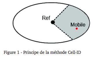
But accuracy depends on cell size, and can be very low in many cases ( The diameter of the GSM cell is between 2km and 20km). As in FIG. 1, where M is the receiver to be located and Ref Is the issuing reference.
4.2 Localisation par « Angles d’Arrivée » (Angle of Arrival)
La technique de l’angle d’arrivée (angle of arrival – AoA en anglais) est basée sur l’exploitation des angles des signaux émis par le tag mobile à au moins deux tags de référence. La position du mobile est donnée par l’intersection des droites passant par chaque référence et d’angle les AoA calculés par rapport à une référence arbitraire. La dimension de chaque faisceau augmente avec la distance par rapport à l’émetteur, ce que résulte à des erreurs plus importantes. Et si l’émetteur se trouve sur la même ligne des deux récepteurs, l’estimation de la position n’est plus possible et un autre récepteur supplémentaire est nécessaire pour réaliser la localisation. [5]

Le principal inconvénient de la technique AoA est la nécessité de disposer de réseaux d’antennes qui augmentent la taille et les coûts des équipements [1][6]. L’autre point négatif est la forte influence des trajets multiples sur la précision de l’estimation [7].
4.2 Angle based technique:Angle of Arrival (AOA)
The angle of arrival (AoA) technique is based on the evaluation of the angles of the signals transmitted by mobile tag with a known location to at least two reference tags. The mobile’s position is given by the intersection of the lines passing through each reference and the AoA defined according to an arbitrary reference. The size of each beam increases with the distance from the transmitter, which results in larger errors. And if the transmitter is on the same line of the two receivers, position estimation is no longer possible and another additional receiver is necessary to realize the location. [5]
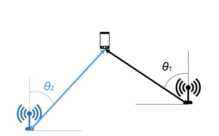
Fig 1.3 Localization based on AOA measurement
The main disadvantage of the AoA technique is the need to have antenna networks that will dramatically increase equipment’s size and costs [1] [6]. The other negative point is the strong influence of multiple paths on the accuracy of the estimate [7].
4.3 Localisation par « Heure d’Arrivée » (Time Of Arrival)
La technique de temps d’arrivée (time of arrival – ToA en anglais) est basée sur le principe que les ondes électromagnétiques se propagent à une vitesse c constante en espace libre (célérité de la lumière). A partir du temps t mis pour que le signal direct arrive de l’émetteur au récepteur et en sachant la vitesse de propagation, la distance d que sépare les capteurs est obtenue directement par l’équation ( 1 )[8] :
D=c.t (1)
Il existe deux classes de techniques : « l’aller simple » et « l’aller-retour ». La première catégorie exige une parfaite synchronisation entre l’émetteur et le récepteur et est utilisée dans le cas des réseaux cellulaires et des communications satellitaires. Elle consiste en envoyer dans le signal transmis l’instant de l’émission et la position du pont de référence de l’émetteur. Tandis que la seconde ne nécessite pas de synchronisation et le signal envoyé par le point de référence est renvoyé par l’objet désirant se localiser avec le temps qui a été utilisé pour traiter et retransmettre l’information.
4.3 Localization technique based Angle of Arrival (TOA)
The time-of-arrival (ToA) technique is based on the fact that electromagnetic waves propagate at a constant speed c in space (celerity of light). From the time t that the direct signal consumed to travel from the transmitter to the receiver and by knowing the speed of propagation, the distance d separated by the sensors is obtained directly by equation (1) [8]:
D = c.t (1)
There are two kinds of techniques: “one-way” and “round-trip”. The first category requires perfect synchronization between transmitter and receiver and is used in cellular networks and satellite communications. It consists in sending the time of transmission and the position of the reference bridge of the transmitter in the transmitted signal. While the second does not require synchronization and the signal sent by the reference point is returned by the object wishing to locate itself with the time that was used to process and re-transmit the information.
Localisation par « Différentiel d’arrivée » (TDoA – Time Difference of Arrival)
Contrairement à la technique ToA, la technique TDoA (time difference of arrival en anglais) n’a pas besoin de synchronisation entre l’émetteur et le récepteur, mais il y a synchronisation entre plusieurs récepteurs avec des positions connues. Ces systèmes sont basés sur l’exploitation de la différence du temps d’arrivée entre les éléments de deux ou plusieurs paires de récepteurs. La TDoA entre les éléments d’un couple de récepteurs ij est exprimé sous la forme de la formule ( 2 ). Une façon d’accéder à la TDoA est de mesurer le retard des signaux arrivant au niveau de chaque récepteur et effectuer leur différence [9].
Avec c la vitesse de propagation des ondes dans le milieu considéré et d la distance de chaque trajet. Pour chaque mesure TDoA, l’émetteur doit se trouver sur une hyperbole avec une différence de distance constante entre les deux unités de mesure [10]. Une localization 2-D peut être estimée à partir des deux intersections de deux ou plusieurs mesures TDoA, comme indiqué dans la Figure 4. Deux hyperboles sont formées à partir de mesures de temps d’arrivée à partir des récepteurs A, B et C afin d’avoir le point d’intersection P.
Figure 4 – Localization based on TDoA measurements
Comme généralement dans le cas des systèmes utilisant cette technique, les récepteurs ne sont pas synchronisés avec l’émetteur (comme la technique ToA) mais uniquement entre eux, la TDoA mesurée ainsi va inclure un offset qui sera en revanche identique à cause de la synchronisation entre les récepteurs. Une autre method d’estimation de la TDoA est la corrélation entre les signaux reçus aux différents récepteurs, cette méthode est aussi appelée de Cross-Corrélation Généralisée (CCG) [11].
En résumé, la valeur de TDoA qui est une valeur de différence de temps sur deux récepteurs distincts peut être calculée par deux techniques différentes :
1. Soustraction de temps d’arrivée (ToA) de chacun des capteurs.
2. Corrélation de deux signaux provenant des capteurs.
Le principal inconvénient de cette méthode est que, dans les environnements avec la présence des multi-trajets les performances se dégradent considérablement [9][11].
4.4 Localization technique based of Time Difference of Arrival TDoA
Unlike the ToA technique, time-of-arrival (TDoA) technique does not require synchronization between the transmitter and the receiver, but there is synchronization between several receivers with known positions. These systems are based on the use of the difference of the arrival time between the elements of two or more pairs of receivers. The TDoA between the elements of a pair of receivers ij is expressed in the form of formula (2). One way to access the TDoA is to measure the delay of the signals arriving at each receiver and make their difference [9].
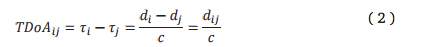
With c the waves’ speed of propagation and d the length of each path. For each TDoA measure, the transmitter must be on a hyperbola with a constant distance difference between two measure units [10]. A 2-D localization can be estimated from the two intersections of two or more TDoA measurements, as shown in Figure 4, two hyperbolas are formed from arrival time measurements from the A, B and C receivers to To have the point of intersection P.
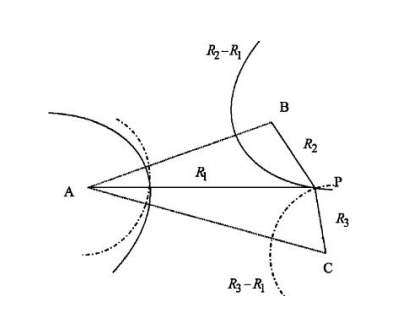
Figure 4 – Localization based on TDoA measurements
As is generally the case for systems using this technique, the receivers are not synchronized with the transmitter (such as the ToA technique) but only with each other. The TDoA thus measured will include an offset which will be identical due to the synchronization Between the receivers. Another method of estimating TDoA is the correlation between the signals received at the various receivers, this method is also called the Generalized Cross-Correlation (GCC) [11].
In summary, the value of TDoA which is a time difference value on two distinct receptors can be calculated by two different techniques:
1. Subtract arrival time (ToA) from each of the sensors.
2. Correlation of two signals from the sensors.
The main disadvantage of this method is that in environments with multi-paths, the performances degrade considerably [9] [11].
Localisation par « Puissance du Signal Reçu » (RSS – Received Signal Strength)
La méthode de puissance de signal reçu appelé en anglais ReceivedSignal Strength (RSS) est basée sur le calcul de la distance entre l’émetteuret le récepteur à partir de la puissance du signal reçu associée à un modèle depropagation dans l’environnement. En effet, la puissance du signal direct reçu par unrécepteur est fonction de la distance d séparant l’émetteur et le récepteur. Elle estdonnée par la formule ( 3 ) [13] :
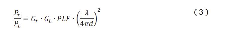
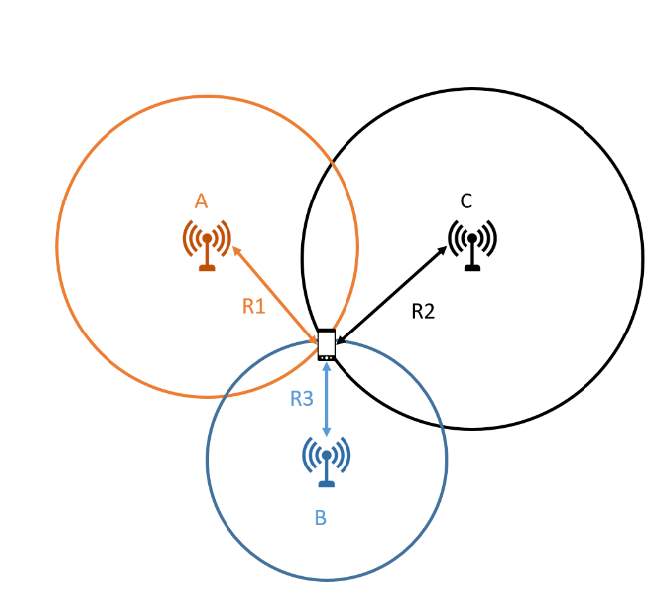
où Pt et Pr est la puissance du signal émis et reçu respectivement, Gt et Gr sont les gains respectifs des antennes de l’émetteur et du récepteur et d est la distance entre les deux antennes. Et le PLF est le « polarisation loss factor » qui quantifie les pertes par rapport au non alignement de polarisation de deux antennes. Il faut au moins trois récepteurs pour déterminer la position en 2D. Cette technique peut utiliser la méthode de trilatération pour déterminer l’emplacement de l’unité mobile, telle que représentée sur la Figure 5. La méthode de la trilatération sera plus détaillée dans la section 1.3.1. Les cercles en pointillés indiquent des erreurs dans les mesures RSS [14].
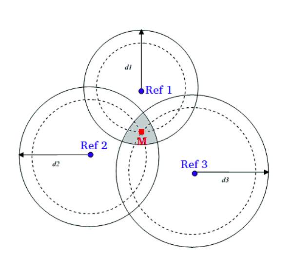
Figure 5 – Localisation par trilatération à partir de trois mesures RSS des références 1, 2 et 3.
La méthode de RSS est très utilisée pour les systèmes de localisation urbain, rural et aussi à l’intérieur. Le principal désavantage de l’utilisation du RSS est l’imprécision de la localisation en présence de multi-trajets dans l’environnement. Par exemple, pour la géolocalisation indoor, il faut estimer les perturbations liées aux obstacles comme les murs, cloisons, vitres, équipements électromagnétiques, etc. Quand l’application est à l’extérieur les perturbations sont moindres et le calcul de l’atténuation est simplifié. Par conséquent, les algorithmes de positionnement basés sur le RSS sont sensibles à l’estimation des paramètres de l’environnement.Pendant cette thèse, le RSS a été choisi comme technique de localisation, et plusieurs méthodes ont été appliquées pour réduire les effets des multi-trajets sur l’erreur de localisation.
4.5.received signal strength based Localization technique (RSS)
The Received Signal Strength method is based on the calculation of the distance between the transmitter and the receiver using the received signal’s power associated with a propagation model. Generally, the power of the direct signal received by a receiver is a function of the distance between the transmitter and the receiver. It is given by the formula (3) [13]:

Where Pt and Pr is the power of the emitted signal and received respectively, while Gt and Gr are the respective gains of the antennas of the transmitter and the receiver and d is the distance between the two antennas. And the PLF is the “polarization loss factor” which weighs the losses related to the non alignment of polarization of two antennas. At least three receivers are required to determine the 2D position. This technique can uses the trilateration method to determine the location of the mobile unit, as shown in Figure 5. The trilateration method will be discussed in more detail in Section 1.3.1. Dotted circles indicate errors in RSSI measurements [14].
Figure 5 – Location by trilateration from three RSS measurements of references 1, 2 and 3.
The RSS method is widely used for urban, rural and also indoor location systems. The main disadvantage of using the RSS is the inaccuracy of the location in the presence of multi-paths in the environment. For example, for indoor geolocation, it is necessary to estimate the perturbations linked to obstacles such as walls, partitions, windows, electromagnetic equipment, etc. When the application is at outdoor, the disturbances are less, therefore, the calculation of the attenuation is simplified. Consequently, the RSS-based positioning algorithms are sensitive to the estimation of environmental parameters. During this thesis, the RSSI was chosen as a localization technique, and several methods were applied to reduce the effects of the multi -travels on the location error.
Technique basée sur les empreintes
La méthode de radiolocalisation basée sur le fait qu’en disposant de façon adéquate les émetteurs et/ou les récepteurs, chaque point d’un espace donné dispose d’une signature (les paramètres du ou des signaux reçus par un mobile à ce point) unique. Pour utiliser cette technique il faut d’abord construire une base d’empreintes en faisant une maillage de la surface totale de localisation pour avoir un certain nombre de points sur tout l’espace de test. Ensuite il faut faire la localisation proprement dite, avec les valeurs de paramètres de localisation identiques à ceux utilisés dans la phase de maillage et finalement avec un algorithme de jumelage la détermination de la position réelle du mobile est possible. Les principaux algorithmes utilisés sont les réseaux de neurones, la méthode du voisin le plus proche ou encore des algorithmes basés les probabilités conditionnelles. Le principal avantage de la technique de radiolocalisation basée sur les empreintes réside dans le fait que le profil de propagation du signal par trajets multiples est incorporé comme information dans les empreintes [12].
4.6 Localization technique based Fingerprint
The radiolocation method is based on disposing the transmitters and / or the receivers appropriately, each point of a given space has a unique signature (the parameters of the signal or signals received by a mobile at this point). In order to apply this technique, firstly, it is necessary to construct a fingerprint database by making a mesh of the total surface of the location to have a certain number of points of the whole test space. Secondly, is to do the localization properly with the values of location parameters identical to those used in the meshing phase; and finally, with the matching algorithm, the determination of the real position of the mobile is possible to be generated. The main algorithms have used are neural networks, the nearest neighbor method or algorithms based on conditional probabilities. The main advantage of the fingerprint-based radiolocation technique is that the propagation profile of the multipath signal is incorporated as information in the fingerprints [12].
1.2.3. Synthèse des techniques de radiolocalisation
Un résumé des principales techniques de radiolocalisation et leurs principaux avantages et inconvénients est donné dans le Tableau 1 extrait de [15]:
1.2.3. Summary of radiolocation techniques
A summary of the main radiolocation techniques and their main advantages and disadvantages is given in Table 1 taken from [15]:
Table 1 – Summary of radiolocation techniques
An alternative way to compare these systems is to analyze the resolution of systems, and in what scales they are normally used. Figure 6 summarizes the location techniques for each environment.
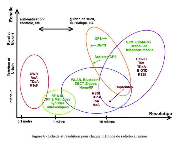
Figure 6 – Scale and resolution for each radiolocation method
1.3. Algorithmes de localisation
Quand un mobile a suffisamment d‘information de distances/angles et de positions, il peut calculer sa position. Pour cela, plusieurs méthodes sont utilisées. Le choix de la méthode de calcul de la position influe sur les performances finales du système de localisation. Ce choix dépend des informations disponibles et des ressources du processeur. Les algorithmes plus utilisées seront discutées sur cette section : la trilatération, la multilatération et la triangulation. Et il existe d’autres méthodes comme le cadre englobant et la position centrale.
When a mobile has sufficient distance / angle and position information, it can calculate its position. For this, several methods can be used. The choice of the method of calculating the position can affect the final performance of the location system. This choice depends on available information and processor resources. The most used algorithms will be discussed in this section: trilateration, multilateration and triangulation. And there are other methods like the encompassing framework and the central position.
5.1. Trilatération et multilatération
La trilatération est la méthode qui calcule la position d’un mobile par l’intersection de trois cercles, comme illustré sur la Figure 7.
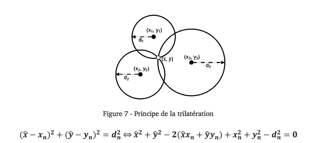
(^x,^y): Position du mobile à localiser.
(xn,yn) : Position des références fixes avec positions connus.
Dans les cas réels, les imprécisions des distances mesurées et des positions rendent le calcul de la localisation très erroné. Une solution du problème consiste à faire la multilatération, c’est-à-dire, définir un système surdéterminé (le nombre d‘équation est plus grand que le nombre d‘inconnus) en utilisant un nombre supplémentaire d’antenne de référence.
5.1. Trilateration and multilateration
Trilation is the method that calculates the position of a moving object by the intersection of three circles, as shown in Figure 7.

(^ X, ^ y): Position of the mobile to be located.
(Xn, yn): Position of fixed references with known positions.
In real cases, the inaccuracies of the measured distances and positions make the calculation of the location very erroneous. One solution to the problem is to do the multilateration, that is to define an overdetermined system (the number of equations is greater than the number of unknowns) using an additional number of reference antennas.
La triangulation [15] ressemble à la trilatération, mais à la place des distances, elle utilise les angles. Il existe deux types de triangulation et les deux utilisent la trigonométrie. Dans le premier cas, voir Figure 8-a, il faut au moins deux references pour estimer l’angle d’arrivée des signaux du mobile à localiser, et pouvoir calculer la position du mobile qui n‘est que l‘intersection des deux droites qui partent des deux mobiles avec les deux angles mesurées respectivement. Ce type de triangulation estsurtout utilisé dans les réseaux de téléphonie mobile. L’autre méthode est l’autolocalisation, voir Figure 8-b. Ce cas est basé sur l’estimation des angles entre le mobile et les antennes émetteurs de base (qui forment un triangle).
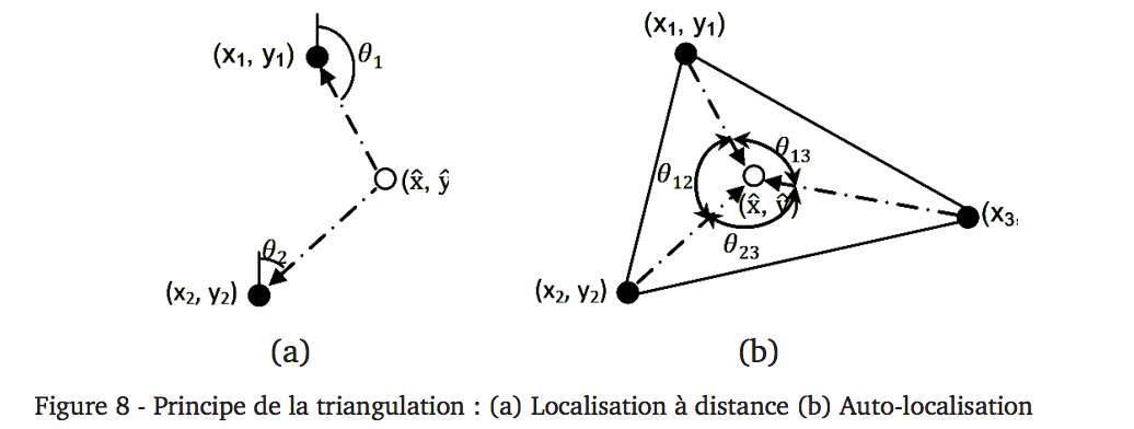
Triangulation [15] resembles Trilateration, but instead of distances, it uses angles. There are two types of triangulation and both use trigonometry. In the first case, see FIG. 8-a, at least two references are needed to estimate the angle of arrival of the signals of the mobile to be located and to be able to calculate the position of the mobile which is only the intersection of the two straight lines starting from the two movements with the two angles measured respectively. This type of triangulation is typically used in mobile telephony networks. The other method is self-localization, see Figure 8-b. This case is based on the estimation of the angles between the mobile and the basic emitter antennas (which form a triangle).

Table 2.5 Comparisons of the three typical localization methods
6 Summary
In this chapter, an overview of mainstream positioning technologies including GPS, A-GPS, Wi-Fi and INS etc. are given. According to comparisons with other positioning systems, Wi-Fi based positioning systems are more favoured for indoor environments. The main challenges using Wi-Fi positioning systems for indoor environments are also discussed and an overview of smartphone technologies is presented. Four types of measurements (i.e. TOA, TDOA, AOA and RSS) for positioning are elaborated and three most commonly used estimation methods for indoor positioning are introduced and inter-compared. Four fingerprinting algorithms including NN, KNN, Weight-KNN and Bayesian algorithms are introduced and their specific characteristics are examined.
Dans ce chapitre nous avons fait un état de l’art sur les techniques et systèmes de localisation.
D’abord, nous avons montré le panorama des technologies utilisés pour la radio localisation : Cell ID, AoA, RSSI, ToA, TDoA et la technique basée sur les empreintes avec la présentation du principe et les avantages et désavantages de chaque une. La méthode de RSSI a été utilisée comme technique de localisation pendant cette thèse.
Ensuite, nous avons expliqué les principes des deux principaux algorithmes de localisation : la triangulation et la trilatération. Ils sont deux méthodes qui sont souvent confondue. La première est basée sur les angles. Par contre la deuxième est basée sur les trois cercles ou plus à partir de la distance calculée à partir des technologies présentées précédemment.
Pour finaliser, des exemples des systèmes de radiolocalisation ont été présentés. Les systèmes qui sont utilisés dans la vie quotidienne, soit pour la localisation dans un petit ou grand environnement. Les systèmes étudiés sont le positionnement par les satellites, le radar, le système RTLS basé sur RSSI, etc. Dans le prochain chapitre nous étudierons plus précisément le scenario de propagation pour la localisation indoor basée sur la technique RSSI et ses contraintes.
In this chapter we have made a state of the art on localization techniques and systems.
First, we showed the panorama of technologies used for radio localization: Cell ID, AoA, RSSI, ToA, TDoA and fingerprint-based technique with the presentation of the principle and the advantages and disadvantages of each. The RSSI method was used as a localization technique during this thesis.
Then, we explained the principles of the two main localization algorithms: triangulation and trilateration. These two methods are often confusing. The first one is based on angles, while the second one is based on the three or more circles from the distance that calculated from the technologies presented previously.
To sum up, examples of radiolocation systems were presented with systems that are being used in everyday life, either for localization in a small or large environment. The systems studied are positioning by satellites, radar, the RSSI-based RTLS system, etc. In the next chapter we will study more deeply about the propagation scenario for the indoor localization based on the RSSI technique and its constraints.
Most of the localization systems , a view of the localization technologies that exist , as well as different examples on the nature of the moving objects to be positioned (Robots, people, animals … etc) have been presented in this chapter. All these technologies are not suitable for all indoor environments; in this line many researchers now trying to combine two or more technologies for profits its advantages. Such as hybrid positioning systems RF & ultrasonic, cellular and WLAN, satellite and cellular, satellite and WLAN [17], as to extend the coverage of indoor and outdoor environments to allow a continuity of positioning according to the mobility of users.
Each positioning system uses the same concept. If you have three or more know fixed reference nodes, we can use some mathematical method to determine the location where you are.
[1] Aziz Benlarbi-Delaï, “Radiolocalisation à courtes et moyennes distances par interferometry microondes. Problèmes inverses et nouvelle instrumentation.” Habilitation à diriger des recherches en sciences physiques, Université des Sciences et Technologies de Lille, Mars 2002
[2] [2] K. Pahlavan, and Xinrong Li, “Indoor Geolocation Science and Technogy”, IEEE Communications Magazine, February 2002
[5] Paul Stefanut, “Application des algorithmes de haute résolution à la localisation de mobiles en milieu confiné”, Th. Micro et nano technolgies, acoustique et télécommunications, Lille, 2010.
[6] Qi, Y., Kobayashi, H., and Suda, H., “Analysis of Wireless Geolocation in a Non-Line-of-Sight Environment”, IEEE Transactions on wireless communications, vol. 5, no. 3, March 2006.
[7] Ismail Guvenc, Chia-Chin Chong – “A Survey on TOA Based Wireless Localization and NLOS Mitigation Techniques”, IEEE Communications surveys and Tutorials, Vol. 11, Nr. 3, 3rd Quarter, 2009
[8] Taponecco, L. ; D’Amico, A.A. ; Mengali, U. “Joint TOA and AOA Estimation for UWB Localization Applications”, IEEE Transactions on Wireless Communications, Volume: 10, Issue: 7, Publication Year: 2011 , Page(s): 2207 – 2217
[9] Sinan Gezici – “A Survey on Wireless Position Estimation”, Wireless Personal Communications, Volume 44, pp. 263 – 282, No. 3, October 2007
[10] C. Drane, M. Macnaughtan, and C. Scott, “Positioning GSM telephones,” IEEE Commun. Mag., vol. 36, no. 4, pp. 46–54, 59, Apr. 1998.
[11] Hui Liu, H. Darabi, P. Banerjee, Jing Liu – “Survey of Wireless Indoor Positioning Techniques and Systems”, IEEE Transactions on Systems, Man, and Cybernetics, Part C: Applications and Reviews, Vol. 37, No. 6 , pp. 1067 – 1080, November 2007
[13] [13] T. S. Rappaport, Wireless Communications: Principles and Practice, Second Edition 2002, Prentice Hall PTR
[14] A. Roxin, J. Gaber, M. Wack and A. Nait-Sidi-Moh – “Survey of Wireless Geolocation Techniques”, IEEE Globecom Workshops, 1-9, 2007
[15] Azzedine Boukerche, ―Algorithms And Protocols For Wireless Sensor Networksǁ, Wiley, ISBN: 978-0-471-79813-2, 11-2008
[Zufferey06] J. C. Zufferey, A. Klaptocz, A. Beyeler, J. D. Nicoud, and D. Floreano, A 10-gram
Microflyer for Vision-based Indoor Navigation, presented at the Intelligent Robots
[6] decawave, “Decawave and partnerQuantitec featured in Nokia boott 2016 mobile world congress,” 2016. [Online]. Available: http://www.decawave.com/decawave-and-partner-quantitec-featured-nokia-booth-2016-mobile-world-congress. [Accessed 9 8 2016].
Cite This Work
To export a reference to this article please select a referencing stye below:
Related Services
View all


Related Content
All TagsContent relating to: "Electronics"
Electronics regards the science and technology involved in the development of electrical circuits and electronic devices and equipment that use them.
Related Articles

DMCA / Removal Request
If you are the original writer of this dissertation and no longer wish to have your work published on the UKDiss.com website then please: