Unbalanced Power Plant Voltage Effect on Alternators
Info: 10265 words (41 pages) Dissertation
Published: 20th Aug 2021
Tagged: EngineeringElectronics
Contents
A bird’s eye view of the Network:
1. Working of Combined Cycle Power Plants:
1.2 Major equipment of a Power Plant
1.3 Types of Alternators & Motors
1.4 Power Plant MV & LV networks:
1. High Voltage(132KV) Network:
2. Medium Voltage(15KV) Network:
3. Low Voltage (440V) Network:
1.6 Negative sequence currents:
2.2 Classification of components of vector of unbalance voltages & currents
a) Unequal Load on Distribution Lines
2.4 Consequence of Unbalanced Voltages
a) Effects on Generator and Motor
c) Effects on the distribution Transformer
2.5 How can unbalance be mitigated?
3.1 Analysis of a balanced system:
3.1.2.1 Stations Transformers:
3.1.3 Results of Balances system analysis:
3.2 Unbalanced System analysis:
3.2.3 Results of Unbalanced voltage system analysis:
3.2.4 Effects of Unbalanced voltage system on alternators:
4.2 Types of Voltage Unbalance
4.4 Reasons of Voltage Unbalance
4.5 Methods to Improve Voltage Regulation
4.5.1 Distributed Generation Installed at Substation
4.5.2 Increased Conductor Size or Reduced Conductor Spacing
4.5.3 Load Tap-Changing Transformers
Figures:
Figure 1: Power Plant Single Line Diagram
Figure 2: ABB Alternator Name Plant
Figure 3: 132KV Switch Yard Single line Diagram
Figure 4: Converteam Alternator Name Plate
Figure 5: Synchronous Generator Main parts
Figure 6: Asynchronous generator main parts
Figure 7: Medium Voltage(15KV) Network
Figure 8: Low Voltage(440V) Network
Figure 9: % Voltage unbalance vs % Temperature rise
Figure 10: %Voltage Unbalance Example
Figure 11: Balanced Voltage Network on ETAP
Figure 12: Setting and parameters of Transformer in ETAP
Figure 13:Settings and parameters of Power Transformer in ETAP
Figure 14: Setting and parameters of Generators on ETAP
Figure 15: Bus Loading summary of Balanced voltage system
Figure 16: Image of winding showing heating effects due to voltage unbalance
Figure 17:Image 2 of winding showing heating effects due to voltage unbalance
Figure 18: Image 3 of winding showing heating effects due to voltage unbalance
Figure 19: Image 4 of winding showing heating effects due to voltage unbalance
Figure 20:Image 5 of winding showing heating effects due to voltage unbalance
Tables:
Table 1: % Voltage Unbalance vs Temperature rise
Table 2:Load ratings at Balance Voltage system of 15KV Bus
Table 3: % Voltage Unbalance among 15 KV buses
Table 4: 132KV Line 1 Real time Values
Table 5 132KV Line 2 Real time Values
Table 6 132KV Line 3 Real time Values
Table 7 132KV Line 4 Real time Values
Table 8: Bus loading summary unbalanced voltage analysis ETAP
Table 9: % Voltage unbalance and % heating on 15KV BUS
ABSTRACT
In a under designed power system network, an unbalanced load at the distribution end can cause unbalanced voltage conditions. If a synchronous generator is connected to an unbalanced voltage, then the stator current which due to that voltage will be unbalanced. The unbalanced current give rise to negative sequence currents which cause hot spots (heating) on the stator as well as rotor winding. This heating may increase the winding temperature, which degrades the insulation of the winding and increasing losses eventually decreasing the life expectancy of the winding. Mechanical stress on the shaft is also increased in result of pulsating torque caused by unbalanced currents thus effecting prime mover as well.
In Pakistan where grid is partially stable and losses are in abundance, it is also observed that the heavy loads are not intelligently distributed thus causing load unbalance among all the three phases more over generating harmonics and negative sequence currents.
In our work, we observe the behavior of a power plant unbalance voltage and current conditions which eventually effects the alternator windings, in some cases causes burning up of insulations. Our work indicates the percentage difference between balance and unbalanced system. More over analyzing the adverse effects of voltage unbalance on alternator’s stator & rotor and devising the solutions to minimize the effects through Analysis based analysis.
Our work contributes to the solutions that electrical system can be balanced through several techniques e.g. changing the system configuration through manual and automatic switching operations to transfer load among networks. Reconfiguration can be performed to reduce loss and to balance loading across network. Un-allocating certain type of load especially inductive from the network can also reduce negative sequence currents. More over increasing the core size of alternator cables and crimping joints can increase the capability of alternator winding to with stand the immense voltage unbalance to a certain extent.
INTRODUCTION
A bird’s eye view of the Network:
The below mentioned figure shows the single line diagram of the network,
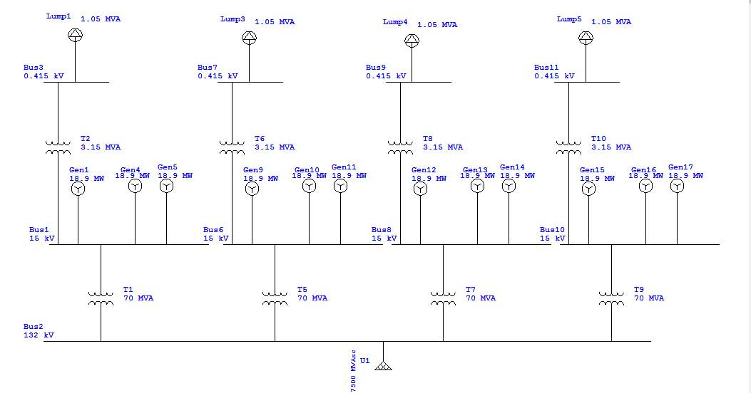
Figure 1: Power Plant Single Line Diagram
Power plant network consists of following equipment:
- Diesel generation sets = 11
- 132/15 KV Power Transformers = 4
- 15KV/440V Auxiliary Transformer = 4
- Grid = 132 KV
- Auxiliary Load = 4 to 5 MW
1 Introduction
In this chapter
- What is combined cycle power plant and there working?
- Equipment installed
- Motors and Generators
- Unbalanced voltages and Negative Sequence Currents
Introduction to Combine Cycle Power Plants
1.1 Introduction
This chapter deals with the introduction and review on the technology of combined cycle thermal power plants installed in Pakistan. Due to shortage of electricity in Pakistan several HFO based thermal combine cycle power plants were installed to meet the peak as well as base Load demand of the country.
HFO based power plants consists of engines driven by fuel and eventually driving the alternator to produce electricity which is eventually fed to the nation grid at different voltage levels. These plants are installed at various locations of Pakistan mainly considering the low voltage levels of the region so that they can be maintained and quality of electricity can be improved.
HFO based combined cycle power plants are usually equipped with prime movers as Engines mainly (Wartsilla, MAN, CAT, Nagata etc.) which runs on heavy furnace oil or diesel and eventually driving the alternators mainly of (ABB, Converteam, Siemens etc.) this simple process is mainly known as the single cycle of a power plant.
In combined cycle power plants, the exhausts of the prime movers/engines are fed to water tube multi stage heat recovery boilers in which high temperature exhaust of the engines heat the water in the tubes and convert it into steam. Steam produced is then fed to the steam turbine mainly (GE, Dresser rand etc.) which eventually drives the alternator and producing electricity.
More over the steam from the exhaust of steam turbine is then fed to the condensers converting the steam to condensate water which can also be used again and again in the boilers to make steam. Slight top up of water is made to the condensate water to maintain the required levels.
In the light of above process such power plants are termed as Combined Cycle Power Plant.
1.2 Major equipment of a Power Plant
Definitions & details of important equipment of power plant that are involved in this study are follows.
It is the fuel oil based engine (MAN 18V48/60B) which is coupled with alternators rotor shaft and drives it. It is an 18 cylinder V shaped medium speed engine having a rated power of 18.428 MW and rated speed of 500 rpm.
- Alternators:
Alternator is the main electricity generator whose rotor shaft is coupled with prime mover and upon rotating and excitation of field current electricity is produced in its stator. Alternator is (ABB AMG1600). It is a synchronous generator having a rated power of 23.035 MVA.


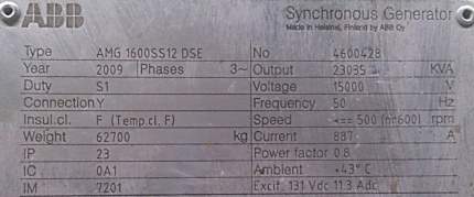
Figure 2: ABB Alternator Name Plant
- Steam Turbine & its Alternator:
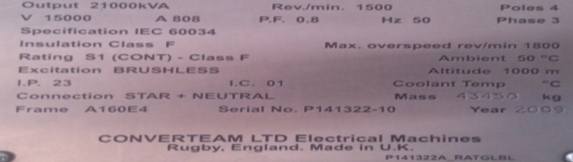
Steam turbine is the essential part of closed cycled system of power plant. Power plant of our study involves the steam turbine of dresser rand HP 20/LP 8 Bar having a rated power of 16.2 MW & rated speed of 6048 rpm. It is coupled to steam turbine’s alternator through speed reduction system. Steam turbine alternator is a synchoronus generator of 21 MVA rated power.

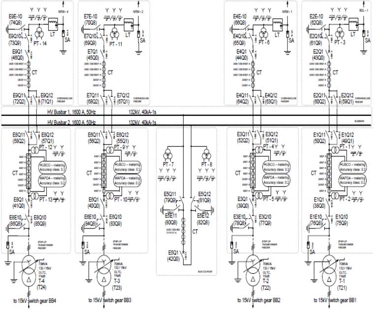
 HV network: 132KV switch yard has been installed with single break double bus scheme 4 different feeders are connected to a single HV bus bar of 7500MVA rating. While the other bus bar of same rating is idle in current scheme.
- Transformers:
There are two types of transformers included in our study. 70 MVA, 132/15 KV Power transformer of AREVA and 3.045 MVA, 15/0.4 KV Auxiliary Transformer of Siemens.
- Auxiliary Equipment:
Equipment that is not involved in direct operation instead used to support he main equipment’s operation is known as auxiliary equipment. At a power plant, there are several types of auxiliary equipment as mentioned below:
- Pumps
- Motors
- Radiator Fans
- Oil Purifiers etc.
1.3 Types of Alternators & Motors
Some of the types of alternators and motors used in power plant are as follows:
- Synchronous
- Generators
- Motors
- Asynchronous
- Motors
- Synchronous Generators:
A residual magnet synchronous generator is a generator where the excitation field is provided by coil powered by a potential transformer which is powered through a single permanent magnet. The term synchronous indicates here that the rotor and magnetic field rotate with the same speed, because the magnetic field is generated through a shaft mounted residual magnet mechanism and current is induced into the stationary armature.[10]

Figure 5: Synchronous Generator Main parts
- Asynchronous Motors (Induction Motors):
Induction motor is an AC motor in which electric current in stator produces field in the rotor and three phase induction motor is an AC motor in which the electric current in the rotor required to produce torque is induced by electromagnetic induction from the magnetic field of stator winding. The induction motor can be made without electrical connections to the rotor. The rotor of an induction motor can be either wound type or squirrel-cage type. A squirrel-cage rotor is the rotating part of the common “squirrel cage” motor. It consists of a cylinder of steel laminations, with aluminum or copper conductors installed in its surface. In operation, the “stator” winding is connected to an AC power source; the AC in the stator produces a rotating magnetic field. The rotor winding has current induced in it through stator field, and produces its own magnetic field. The interaction of the two sources of magnetic field produce torque on the rotor. [10]
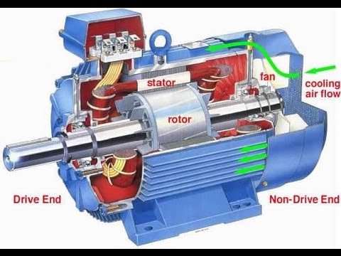
Figure 6: Asynchronous generator main parts
1.4 Power Plant MV & LV networks
Power plant with in itself contains three different voltage levels High Voltage(132KV), Medium Voltage(15KV) & Low Voltage(440V). Every voltage level has its own network specifications and these networks are connected through transformers. Below mentioned are the details on above mentioned individual voltage networks.
Plant HV(132KV) network has already been shown above.
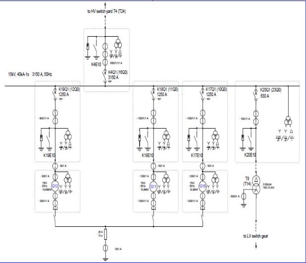
Figure 7: Medium Voltage(15KV) Network
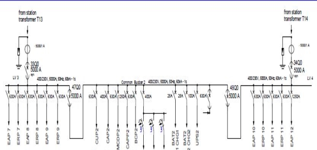
Figure 8: Low Voltage(440V) Network
1.5 Unbalanced Voltages
Unbalanced voltages are unequal voltages on 3-phase network circuits that can exist in a power system. Unbalanced voltages can cause problems, specifically to alternating equipment’s e.g motors, generators & other inductive devices etc. Complete & ideally voltage-balanced circuits are mere imagination in the real-world due to presence of losses in the system especially in the network of Pakistan. Normally difference of few voltages are acceptable and many manufacturers mention the tolerance range of the equipment’s but when voltages differ excessively then problems occur. Unbalanced voltages generally occur because of variations in the load. Unbalanced voltages can be due to different impedances, or type and value of loading on each phase. Fundamentally, the resulting current unbalance is caused not only by the voltage unbalance of the system but also due to the system impedance, the loads which cause the unbalance, and the operating load on equipment, especially motors. Complete phase loss, is the definitive voltage unbalance condition for a three-phase circuit. Specific values should show the impact in a more elaborative way.[1]
The National Electrical Manufacturers Association (NEMA) in its Motors and Generators Standards (MG1) part 14.35[11], defines voltage unbalance as follows:
%age voltage = 100 x (maximum voltage deviation from average voltage)/unbalance (average voltage)
In a three phase AC circuit, current is constituted of positive sequence, negative sequence and zero sequence current. The positive phase sequence current flows as per the load connected to the circuit. The negative phase sequence current will flow due to difference of three phase voltages of the system. If no difference of R Y B voltage is present, the negative sequence current will not flow. The negative phase sequence current present in the circuit will be of same frequency but the phase sequence will be negative to the system sequence. Negative sequence current will cause excessive heating of generator rotor as the rotor will experience double the system frequency so far, the negative sequence current is concerned. The zero-sequence current is present only in case of earth fault otherwise it is absent. [2]
The aim of this report is to analyze the voltage unbalance among different lines, there effects on alternators and plant auxiliary motors, and to provide Analysis based comparison of the system.
More over Objectives of this thesis report are as follows.
- Literature Review: It involves the review of fundamentals concepts of Unbalanced voltages, negative sequence currents & their effects on motor and generators.
- Simulating: it comprises of the Analysis based comparison of balanced and unbalanced voltage system on software (ETAP)
- Parametric study: it includes the analysis of line parameters and their comparison among each other and calculating deviations from average values.
- Optimization: After analyzing different schemes that could have minimized the voltage unbalancing will be suggested e.g.
- Optimizing network
- Increasing cable and crimp sizes etc.
- Report Writing
- Finalizing the project
1.7 Methodology
- The review of basic concepts of unbalanced voltages & negative sequence components.
- The study of cause & effects of unbalanced voltages & negative sequence components
- Analysis of test data and estimating deviation from the average or stable system.
- Simulating the network design on ETAP with both actual and desired values.
- The measured results are compared with simulated one.
1.8 Layout of Thesis Report
Chapter 1:
Introduction
It covers introduction, outline of basics of power plant, types of equipment’s, definition and networks, aims and objectives, methodology.
Chapter 2:
Literature Review
It provides Literature Review, Contextual study of Voltage Unbalance, Negative Sequence and their effects.
Chapter 3:
Computer-Aided Analysiss of Balanced & Unbalanced system
It provides overview of unbalanced system and balanced system behavior
Chapter 4:
Network Optimizing solutions
It presents the in-depth details of Changes in HV switchgear scheme and its effects and Introduction of additional phase balancing equipment into the network.
2 Literature Review
In this chapter
- Reasons of voltage unbalance.
- Effects of unbalanced voltages & negative sequence currents on alternators?
Literature Review
2.1 Introduction
A balanced three phase load is a one which is equally shared among all three phases. Which eventually means that the magnitude of currents in all three phases are equal and are displaced from each other by 120° and thus add up to zero. Hence zero neutral current. If either or both of these conditions are not met, the system is called unbalanced or asymmetrical.
2.2 Classification of components of vector of unbalance voltages & currents
In order to quantify the unbalance in 3-Phase voltages and current, the three-phase system can be replaced by three components of vector:
- Positive Sequence
- Negative Sequence
- Zero Sequence
It represents three equal phasors phase displaced by 120° and has phase sequence same as original phasors. It specifies that the current is flowing through source to load. [2]
It represents three phases displaced by 120° with each other and have phase sequence opposite to that of the original phasors. It specifies that current is flowing from load to source. [2]
It represents three equal and parallel phasors with zero-degree phase displacement. It specifies current is flowing from source to ground
A balanced three phase system operating in normal condition, only positive sequence component exists. [2]
2.3 Causes of unbalance
Following are the causes of unbalanced of voltages.
- Unequal Load on Distribution lines
- Non-Linear Load
- Malfunctioning Equipment
Most of the domestic loads and industrial lighting loads are single phase. However, these loads are fed from three phase supply. If the load divisions among different phases are not coordinated, the phase parameters may differ from each other causing unbalanced demand from the supply. The negative or zero sequence voltages in a power system typically result from unbalanced loads causing negative or zero sequence currents to flow.[3]
When a sinusoidal voltage is applied to a certain type of load, the current drawn by the load is proportional to the voltage and impedance and follows the envelope of the voltage waveform. These loads are referred to as linear loads.
Some loads cause the current to vary disproportionately with the voltage during each half cycle. These loads are classified as nonlinear loads, and the current and voltage have waveforms that are no sinusoidal [2], containing distortions, whereby the 50-Hz waveform has numerous additional waveforms superimposed upon it, creating multiple frequencies within the normal 50-Hz sine wave.
- Positive sequence harmonics (harmonic numbers 1,4,7,10,13, etc.) produce magnetic fields and currents rotating in the same direction as the fundamental frequency harmonic.
- Negative sequence harmonics (harmonic numbers 2,5,8,11,14, etc.) develop magnetic fields and currents that rotate in a direction opposite to the positive frequency set.
- Zero sequence harmonics (harmonic numbers 3,9,15,21, etc.) do not develop usable torque, but produce additional losses in the machine.
The interaction between the positive and negative sequence magnetic fields and currents produces oscillations of the motor shaft. The permissible limit in terms of percentage of negative phase sequence current over positive sequence current is 1.3% ideally but acceptable up to 2%.[4]
The utility can be the source of unbalanced voltages due to malfunctioning equipment, including blown capacitor fuses, open-delta regulators, and open-delta transformers. Open-delta equipment can be more susceptible to voltage unbalance than closed-delta since they only utilize two phases to perform their transformations.
The facility housing the motor can also create unbalanced voltages even if the utility supplied voltages are well balanced. Resistive and inductive unbalances within the motor equipment lead to unbalanced voltages and currents. Defects in the power circuit connections, the motor contacts, or the rotor and stator windings, can all cause irregular impedances between phases in the motor that lead to unbalanced conditions. [7]
2.4 Consequence of Unbalanced Voltages
Unbalanced voltages indicate the existence of Negative Sequence Current that is harmful for both Generation Side and Consumer Side.
Unbalanced currents will generate negative sequence components which in turn produces a reverse rotating filed (opposite to the synchronous rotating filed normally induces emf in to the rotor windings) in the air gap between the stator and rotor of the machines. [6]
This reverse rotating magnetic field rotates at synchronous speeds but in opposite direction to the rotor of the machine. With respect to the rotor surface, this reverse rotating magnetic fields induces double frequency currents into the rotor. This resulting induced currents into the rotors will provide high resistance path to the normal induced currents (generated due to synchronous rotating magnetic field) resulting in the rapid heating. This heating effect in turn results in the loss of mechanical integrity or insulation failures in electrical machines within seconds. Therefore, it is undesirable to operate the machine during unbalanced condition when negative sequence currents flow in the rotor and has to be protected. [6]
The graph below shows the relationship between voltage unbalanced and temperature rise, which approximately increases by twice the square of the percentage of voltage unbalance.
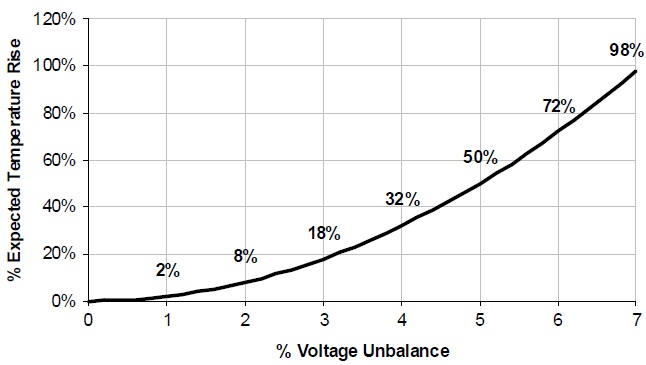
Figure 9: % Voltage unbalance vs % Temperature rise
Current imbalance can also be caused by voltage imbalance and a temperature rise a lot greater than the percentage of voltage imbalance. We can calculate the increased temperature in a synchronous motor winding as a result of voltage imbalance. [5]
To calculate the system imbalance and the temperature rise in the winding, the following formulae are used:
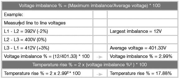
Figure 10: %Voltage Unbalance Example
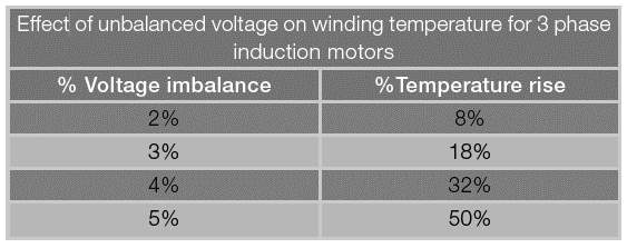
Table 1: % Voltage Unbalance vs Temperature rise
The table in Figure 2 shows the exponential winding temperature increase compared with the increase in voltage imbalance. An imbalance greater than 2% is unacceptable as it results in a temperature rise in the winding that will be more than the motors specification; the life expectancy of the motor may be decrease. NEMA limits require no more than 5% unbalanced voltage. Studies show that the average life expectancy of insulation becomes half with every 10° of temperature increase. The increased operating heat also induce premature expiration of the motor, excess current is also drawn without any additional power output, therefore over-stressing the supply cables and reaching levels where the current overloads and the Variable Speed Drives (VSD) over current protection will trip. [5]
Transformers subject to negative sequence voltages transform them in the same way as positive-sequence voltages. The behavior with respect to zero sequence voltages depends on the primary and secondary connections and, more particularly, the presence of a neutral conductor. If, for instance, one side has a three-phase four-wire connection, neutral currents can flow. If at the other side the winding is delta connected, the zero-sequence current is transformed into a circulating (and heat-causing) current in the delta.[12]
Transformer offers high reactance to negative phase sequence currents and thus reduces the level of unbalance on the other side of the system.
Ideally any distribution transformer gives best performance at 50% loading and every electrical distribution system is designed for it. But in case of unbalance the loading goes over 50% as the equipment’s draw more current.
Following data represents the efficiency of transformer under different loading conditions
- Full Load- 98.1%
- Half Load- 98.64%
- Unbalanced loads- 96.5%
For a distribution transformer of 200KVA rating, the eddy currents accounts for 200W but in case of 5% voltage unbalance they can rise up to 720W [12].
An unbalance of 1% is acceptable as it doesn’t affect the transmission lines. But above 1% it increases linearly and at 4% the de-rating is 20%. This implies that 20% of the current flowing in the transmission will be unproductive and thus the copper losses will increase by 25% at 4% unbalance.[6]
- For motors, an unbalance of 5% will result in capacity reduction by 25%. That means, the motor current will increase to match the equipment’s torque needs which will result in proportional copper losses in motor. The voltage unbalance of 3% increase the heating by 20% for an induction motor.
- The resistance for negative sequence current is 1/6th of the positive sequence current which means a small unbalance in voltage waveform will give more current and thus losses.
2.5 How can unbalance be mitigated?
To decrease the effects of unbalance, several actions can be taken, with different degrees of technical complexity.
- The first and most basic solution is to rearrange or redistribute the loads in such a way that the system becomes more balanced.
- Reducing the harmonics also reduces the unbalance, which can be done by installing reactive or active filters. These filters reduce the negative phase sequence currents by injecting a compensating current wave.
- In case the disturbing loads cannot be replaced or repaired, connect them with high voltage side this reduces the effects in terms of percentage and even controlled disturbance in low voltage side.
- Motors with unbalanced phase reactance should be replaced and re-winded.
- Another type of mitigation technique is the use of special transformers, such as Scott- and Steinmetz transformers:
The ‘Scott-transformer’ consists of two single-phase transformers, with special winding ratios, hooked up to a three-phase system. They are connected in such a way that at the output, a two-phase orthogonal voltage system is generated allowing the connection of two single-phase systems. This set-up presents a balanced three-phase power to the grid.[12]
A ‘Steinmetz-transformer’ is in fact a three-phase transformer with an extra power
balancing load, consisting of a capacitor and an inductor rated proportional to the single-phase load. When the reactive power rating of the inductor and the capacitor equals the active power rating of the load, divided by √3, the three-phase grid sees a balanced load. The three-phase rated power of the transformer equals the single-phase load’s active power. Note that balancing is only perfect for loads with an active power equal to the value used to design the system.[12]
2.6 Conclusion
After a deep study of previous literature, it was concluded that the occurrence of unbalanced phase voltages will give rise to negative sequence currents which will cause heating and deuteriation of alternating & induction machines. Thus, to minimize the phase unbalance effects network to be optimized so that it can handle the phase unbalance issue more over cable sizes along with crimp connections to be upgraded with large core size cables and crimps.
3 Analysis of balanced and unbalanced system
In this chapter
- Analysis based on values of balanced power system.
- Analysis based on values of unbalanced power system.
- Difference and its effecting parameters.
3.1 Analysis of a balanced system
In order to study the balanced scenario of our system ETAP 12.0 is used on which the model of power plant was created along with actual settings of equipment’s e.g. Transformers, Alternators, Bus bar etc. and real-time values of load both on HV and LV side are fed into the system to make the analysis as realistic as possible.
3.1.1 Network Diagram
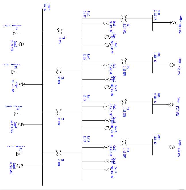
Figure 11: Balanced Voltage Network on ETAP
3.1.2 System Settings
Settings placed in for the equipment’s are as follows in the form of snapshots of ETAP 12.0
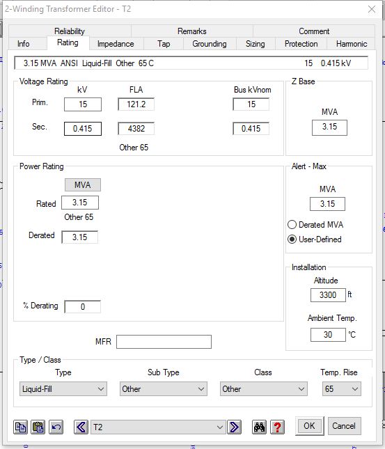
Figure 12: Setting and parameters of Transformer in ETAP
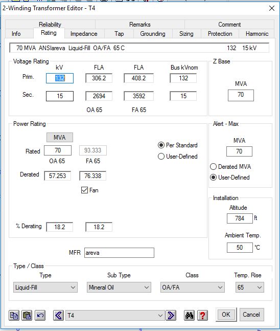
Figure 13:Settings and parameters of Power Transformer in ETAP
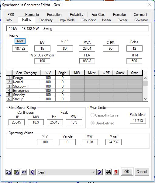
Figure 14: Setting and parameters of Generators on ETAP
3.1.3 Results of Balances system analysis
Summary of results of balanced system analysis are as follows:
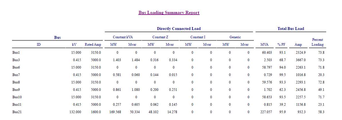
Figure 15: Bus Loading summary of Balanced voltage system
As according to balanced system summary report the load is balanced on every phase of an individual bus. While the system overall voltage has a difference as follows
| Bus | Amp |
| 1 | 2324.9 |
| 6 | 2263.1 |
| 8 | 2293.1 |
| 10 | 2257.5 |
Table 2:Load ratings at Balance Voltage system of 15KV Bus
| % Difference among 15KV Buses | |
| Bus 1 & 6 | 3% |
| Bus 1 & 8 | 1% |
| Bus 1 & 10 | 3% |
| Bus 6 & 8 | 1% |
| Bus 6 & 10 | 0% |
| Bus 8 & 10 | 2% |
Table 3: % Voltage Unbalance among 15 KV buses
% difference = ((A-B)/(A+B)/2) x 100
thus, as per Voltage unbalance and temperature rise formula as discussed in chapter # 2 we can say that the temperature rise is zero due to zero % voltage unbalance while if we see at MV bus bars they all have a minor load difference due to system losses as well as difference in load demand on different lines.
Balanced system detailed report comprises of following parts:
- Bus input data
In this section the Bus ratings along with their type and their capacity is mentioned.
- Winding transformer input data
In this section the transformers ratings along with their type, capacity and tap settings are mentioned.
- Branch connections
In this section the loading schemes of buses are mentioned along with their individual resistance, reactance & impedance.
- Load flow report
Load flow report depicts the load flow on every bus along with their flow to and from other buses, load flow reports plays a very vital role in our study it helps us to analyze loading rates among the busses and eventually the findings from load flow report helps in calculating % imbalance of voltage among different phases of generators or buses.
- Bus loading summary report
- Branch loading summary report
- Branch losses summary report
- Summary of total generation, loading and demand
3.2 Unbalanced System analysis
3.2.1 Network Design
Network design of the unbalanced system is the same as that of balanced system design mentioned in figure 11.
3.2.2 System settings
System setting for the unbalanced system are also same as mentioned in figure 12, figure 13, & figure 14 .Real-time data has been used for accurate analysis.
Real-time data has been taken form the differential protection relays (MICOM P422 Differential Protection Relay, MICOM P122 Over Current Relay) installed at every outgoing line. Data has been taken on different date, time and load demands for all four lines.
Line 1:
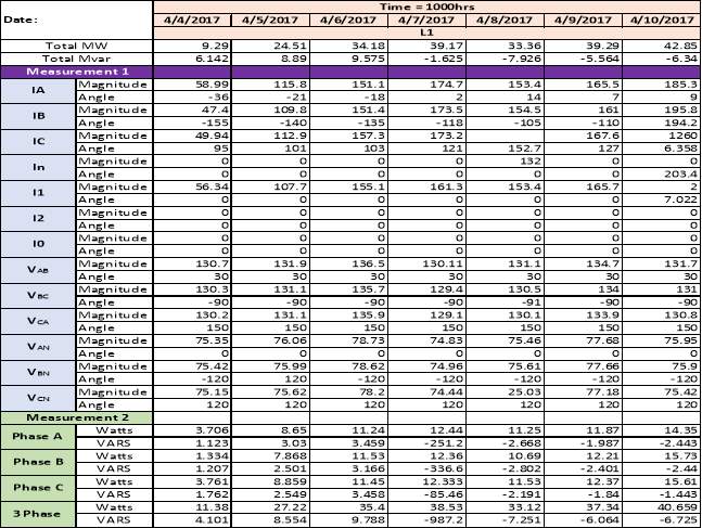
Table 4: 132KV Line 1 Real time Values
Line 2:
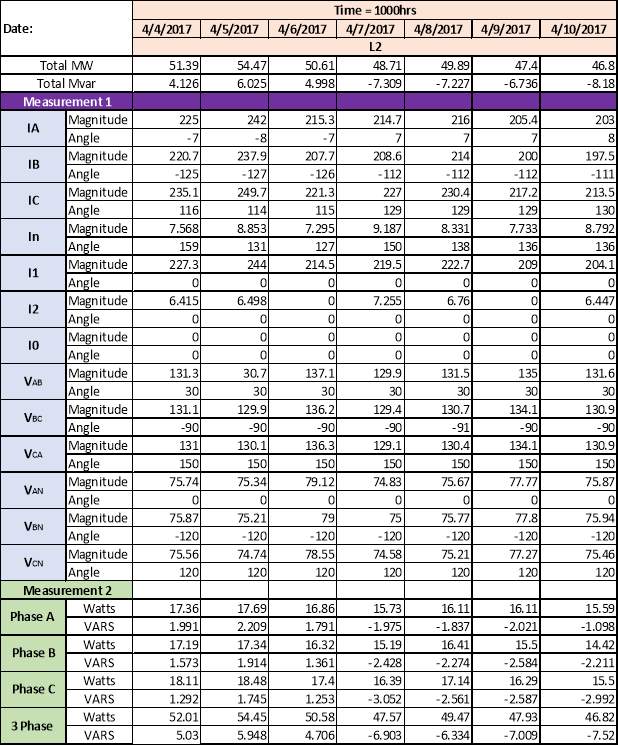
Table 5 132KV Line 2 Real time Values
Line 3:
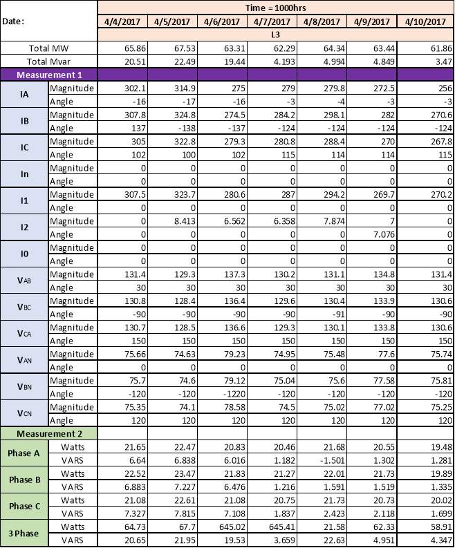
Table 6 132KV Line 3 Real time Values
Line 4:
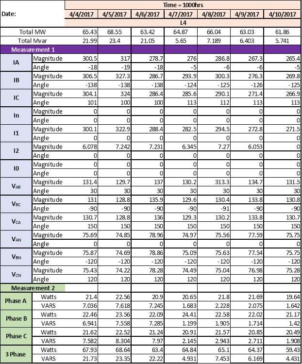
Table 7 132KV Line 4 Real time Values
3.2.3 Results of Unbalanced voltage system analysis
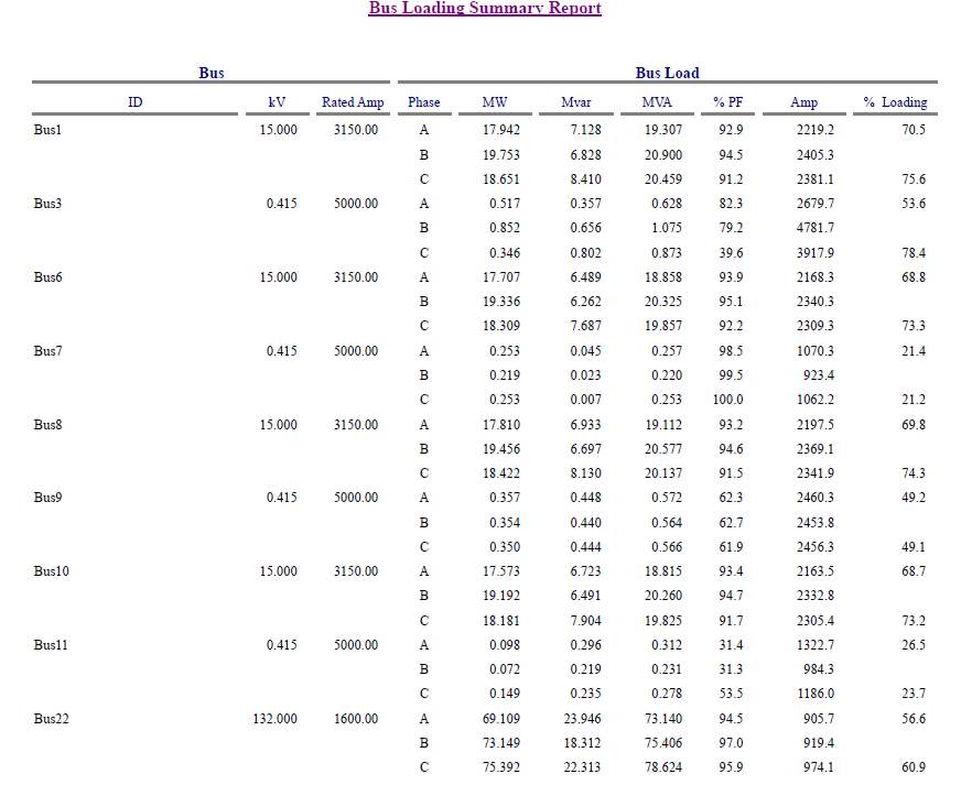
Table 8: Bus loading summary unbalanced voltage analysis ETAP
According to the unbalanced system voltage analysis it has been seen that there exists difference among the load of all three phases of 400V, 15 KV & 132KV bus. As our major concern is with the voltage unbalance on the 15 KV bus thus the analysis of unbalanced voltages on it is analyzed in the sheet below along with percentage heating caused due to it.
% Voltage Unbalance = (Maximum Imbalance/Average Voltage) X 100
% Heating =2 X (% Voltage Unbalance)2
| Bus Loading Summary Report conventional scheme lump load | ||||||||||
| BUS # | Phase
Difference |
Actual
% Voltage Imbalance |
Voltage Imbalance above 8% | % Heating
Above 8% |
Amp | MW | MVAR | MVA | % PF | KV |
|
Bus1
|
A to B | 9.7375 | 1.74 | 6 | 2219 | 17.9 | 7.1 | 19.3 | 93 | 15.48 |
| B to C | 9.0604 | 1.06 | 2 | 2405 | 19.8 | 6.8 | 20.9 | 95 | 14.04 | |
| C to A | 9.0005 | 1.00 | 2 | 2381 | 18.7 | 8.4 | 20.5 | 91 | 14.71 | |
|
Bus6
|
A to B | 8.9434 | 0.94 | 2 | 2168 | 17.7 | 6.5 | 18.9 | 94 | 15.68 |
| B to C | 8.9694 | 0.97 | 2 | 2340 | 19.3 | 6.3 | 20.3 | 95 | 14.34 | |
| C to A | 8.9883 | 0.99 | 2 | 2309 | 18.3 | 7.7 | 19.9 | 92 | 14.99 | |
|
Bus8
|
A to B | 9.0075 | 1.01 | 2 | 2198 | 17.8 | 6.9 | 19.1 | 93 | 15.59 |
| B to C | 9.0271 | 1.03 | 2 | 2369 | 19.6 | 6.7 | 20.6 | 95 | 14.24 | |
| C to A | 8.9867 | 0.99 | 2 | 2342 | 18.4 | 8.1 | 20.1 | 92 | 14.90 | |
|
Bus10
|
A to B | 8.9467 | 0.95 | 2 | 2163 | 17.6 | 6.7 | 18.8 | 93 | 15.80 |
| B to C | 6.8329 | 1.17 | 3 | 2333 | 19.2 | 6.5 | 20.3 | 95 | 14.45 | |
| C to A | 5.7615 | 2.24 | 10 | 2305 | 18.2 | 7.9 | 19.8 | 92 | 15.10 | |
Table 9: % Voltage unbalance and % heating on 15KV BUS
As per ABB the voltage unbalance allowed is 8% or in other words ABB Alternator with has the capacity to with stand the heating of 8% voltage unbalance.
3.2.4 Effects of Unbalanced voltage system on alternators
As proved above that due to voltage unbalance 2% to 6% heating increases above the bearable capacity of the alternator. Below mentioned are some of the figures showing actual heating effect on the alternator winding.
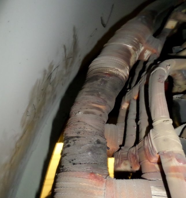
Figure 16: Image of winding showing heating effects due to voltage unbalance
Image showing black spots on the winding due to excessive heating
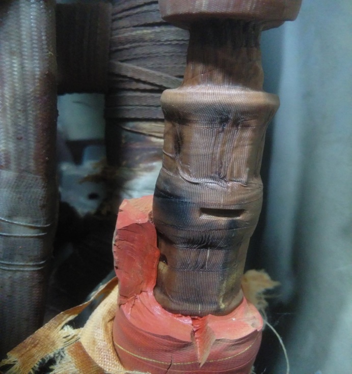
Figure 17:Image 2 of winding showing heating effects due to voltage unbalance
Image showing blackened winding insulation due to excessive heating
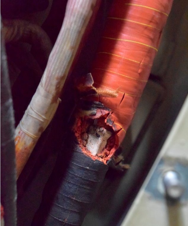
Figure 18: Image 3 of winding showing heating effects due to voltage unbalance
Image showing damaged brittle insulation due to excessive heating
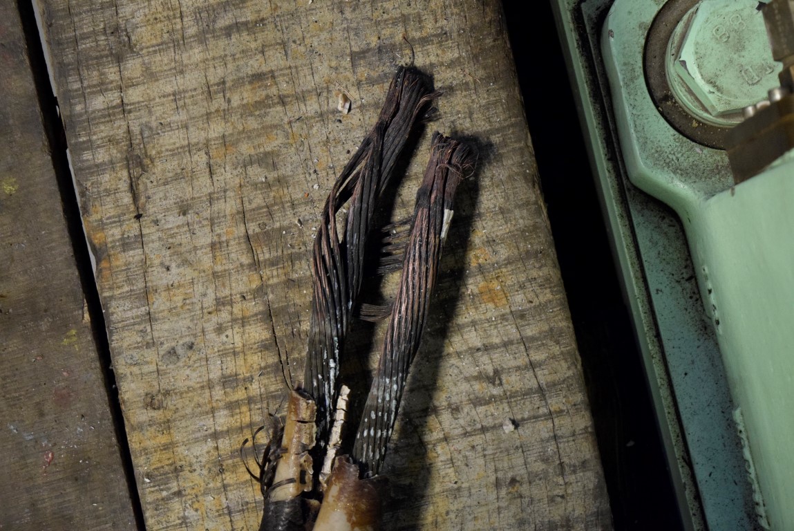
Figure 19: Image 4 of winding showing heating effects due to voltage unbalance
Image showing blackened cables of alternator due to excessive heating
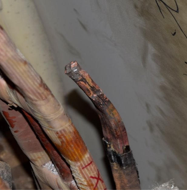
Image showing blackened winding of alternator due to excessive heating
Figure 20:Image 5 of winding showing heating effects due to voltage unbalance
As shown in above pictures the adverse effects of heating on the health of alternator’s winding and its insulation, voltage unbalance majorly contributes to create such heating.
Furthermore, detailed report of Unbalanced analysis of the network is attached in Appendix-II.
In order to resolve such issues Voltage Unbalance shall be reduced and efforts to be made to make system balanced as maximum as possible.
Some of the solutions are proposed based on the literature review, industrial practice and experience are mentioned in Chapter 4.
4 Network based solutions
In this chapter
- Changes in HV switchgear scheme and its effects.
- Introduction of additional phase balancing equipment into the network.
4.1 Introduction
Voltage unbalance which is a common and global phenomenon is found to be very effective in deteriorating the operation and performance of electrical apparatus. Voltage unbalance is the deviation of individual phase voltage magnitudes from the normal or rated values, with the individual phase voltage being not equal to each other either in magnitude and/or in phase displacement.
4.2 Types of Voltage Unbalance
The voltage unbalance can be classified into two types:
- Over Voltage Unbalance (OVU)
- Under Voltage Unbalance (UVU)
OVU is a condition when the three phase voltages are not equal to each other, in addition positive sequence component is greater than the rated value while UVU is a condition where the three phase voltages are not equal to each other, and in addition the positive-sequence component is lesser than the rated value.[3]
4.3 Unbalance Definition
The two general definitions for voltage unbalance as described are;
- NEMA Definition
The voltage unbalance percentage (VUP) at the terminal of a machine as given by the National Electrical Manufacturer Association Motor and Generator Standard (NEMA MGI) used in most studies is[11]
VUP %=Max Voltage Deviation from Avg. Line VoltageAvg. Line Voltage×100
- Symmetrical Component Definition (IEC)
The voltage unbalance factor (VUF) is defined by International Electro Technical Commission (IEC) as the ratio of negative-sequence voltage component to the positive-sequence voltage component[1]
VUF %= VnVp×100
Where Vn and Vp are magnitude of negative and positive sequence voltage.
4.4 Reasons of Voltage Unbalance
The presence of inequality in phase voltage can be due to:
- Unbalance Phase Demand
- Non- Uniform Air Gap
- Damaged Generator Winding
- Fault in Transmission Lines
In the Power Plant the Voltage Unbalance is surly due to Unbalanced Load. If unbalance occur due to Non- Uniform Air Gap, Winding Short Circuit the Protection should detect this.[7]
4.5 Methods to Improve Voltage Regulation
Unbalanced three phase voltages have a significant effect on the design and operation of transformers and induction and synchronous machines. It is important to keep the three-phase circuits as closely balanced as possible to prevent overloading the equipment on the highest loaded phase. The amount of Phase Unbalanced should be less than 2%.
There are various Method available for both Generation Side and Substation/Distribution side to keep the voltages in allowable limits.
- DG voltage regulators (VRs)
- Apply capacitors
- Apply voltage-regulating equipment
- Balance the loads
- Transfer loads to other substations.
- Increased Conductor Size or Reduced Conductor Spacing
- Load Tap-Changing Transformers
- Transposition
4.5.1 Distributed Generation Installed at Substation
The generator bus voltage can be regulated to maintain a fixed voltage for changes in load and reactive requirements. The generator field current can be varied to match the changes in load current. The voltage can be increased or decreased as the load increases or decreases.
4.5.2 Increased Conductor Size or Reduced Conductor Spacing
Increasing conductor size is an expensive method to achieve improved capacity to withstand the heating effects caused by voltage unbalance. Increasing the size of the conductor reduces the resistance and, thus, the voltage drop and real losses. However, it may necessitate a rebuilding of the line because of the larger and heavier conductor. An alternative is to reduce the spacing between the phase conductors, which reduces the reactance and lowers the voltage drop.
4.5.3 Load Tap-Changing Transformers
LTC transformers are often referred to as tap-changing under load. Load tap changers are applied to power transformers at the substation. They are used to control the voltage on the LV or secondary side to a fixed value with a variable primary voltage input. Also, LTCs may be used to control reactive power flow by shifting the phase angle of the transformer secondary voltages. [12]
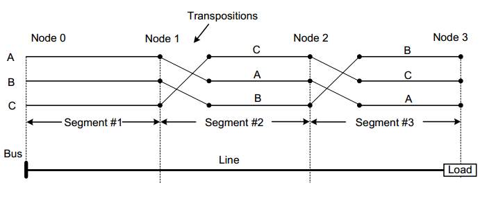
4.5.4 Transposition
The voltage unbalance may exist because the transmission lines are not fully transposed to balance the line impedance. The voltage unbalance can be reduced if transposition is done properly. [8]
4.6 Conclusion
This thesis presents a comparative analysis between balanced & unbalanced voltage system based on real time values of a power plant installed in Pakistan. In the comparison the issue of % voltage unbalance and heating effects due to it was shown. More over the actual demonstration of the effected alternators and its parts was also included. It has been proven that % Voltage Unbalance not only effects the machinery at distributed end but also on the generation end.
This could cause alternators a notice able drop in their life expectancy.
More over a short-term solution based on the industrial practice has also been shared through which the capacity of an alternator to withstand heating effects more than its designed limit increases but this is only short term solution and a lot more future work is required to present a long term viable solution to the problem of % Voltage Unbalance.
4.7 Future Work
In Future, further extension of this work can be carried out in order to reduce % Voltage Imbalance through network optimization and also an improvement can be made by improving grid and load distribution schemes so that the life expectancy of such expensive and important machines can be increased.
References
Effect of Unbalanced Voltage on Operation of Induction Motors and Its Detection Davar Mirabbasi1, Ghodratollah Seifossadat2 , Mehrdad Heidari1,
Mohsen Hamzeh, Houshang Karimi, Hossein Mokhtari, “Harmonic and Negative Sequence Current Control in an Islanded Multi-Bus MV Microgrid”, IEEE Transactions On Smart Grid, Vol. 5,No. 1, January 2014
Limits for Voltage Unbalance in the Electricity Supply System, Version 1.0, 30th November 2005, Prepared by- Abu Dhabi Distribution Company, Al Ain Distribution Company and RASCO.
De-rating of Induction Motors Operating with a Combination of Unbalanced Voltages and Over- or Under-voltages- P.Pillay, Jean Newell Distinguished Professor in Engineering, Clarkson University AND P.Hofmann, Manager of Power Quality , Manhattan, NY.
ABB AVC White paper on Unbalanced voltage supply the damaging effects on three phase induction motors and rectifiers
Three-Phase Induction Motor’s Torque under Voltage Unbalance By Sobhan Ghanbari, Pezhvak Sheikhzadeh-Baboli & Rouhollah Falahati-Naghib K. N. Toosi University of Technology, Iran Islamic Republic
C.Y.Lee, B.K.Chen, W.J.Lee, ―Effects of unbalanced voltage on the operation performance of a three-phase induction motor‖ , IEEE Trans. Energy Convers. , vol. 14, no. 2, pp. 202–208, Jun. 1999.
Negative Sequence Currents from an Unbalanced Transmission System Daniel W. Durbak
NEMA Standards Publication MG 1-1998 Motors and Generators
A. H. Al-Badi, A. Elmoudi, I. Metwally, A. Al-Wahaibi, H. Al-Ajmi, M. Al-Bulushi, “Losses Reduction In Distribution Transformers”, Proceeding of the international Multi Conference of Engineers and Computer Scientist 2011. Vol. 2, March 16-18, 2011, Hong Kong.
Cite This Work
To export a reference to this article please select a referencing stye below:
Related Services
View all


Related Content
All TagsContent relating to: "Electronics"
Electronics regards the science and technology involved in the development of electrical circuits and electronic devices and equipment that use them.
Related Articles

DMCA / Removal Request
If you are the original writer of this dissertation and no longer wish to have your work published on the UKDiss.com website then please: