Vehicle Stability Control Systems
Info: 3426 words (14 pages) Dissertation
Published: 10th Dec 2019
Tagged: EngineeringMechanics
1
To respect the design of the well tuned passive vehicle, the proposed controller will not stabilize the vehicle during steady state maneuvers. So no ZSS for the whole operating range of the vehicle.
2
3 Literature Review
3.1 Chapter Introduction
This chapter will provide a review of past studies involving yaw moment control methods and more specifically using rear axle steering. This review will provide a guideline on how to implement rear steering into a future 8×8 combat vehicle. The majority of research has been completed on a 4-wheel, 2 axle vehicle, however the research points can be interpreted into a 4 axle 8×8 vehicle.
3.2 Vehicle Stability Control systems
In the automotive industry today, it is extremely unlikely to find a consumer vehicle to be offered without a driver aid control system. Since the introduction of these systems, the focus has expanded to include vehicle performance instead of just vehicle safety. The development of stability control systems originates from Anti-lock Braking Systems (ABS) and Traction Control Systems (TCS) which aided in maintaining directional stability of the vehicle during emergency situations. These systems limit the longitudinal wheel slip and lock up through active manipulation of the throttle and braking. When the tires are operating at the slip of maximum adhesion, the shortest braking distances and most efficient accelerating times can be achieved [1]. Further developments aimed towards regaining stability during the event of the vehicle heading in an undesired direction by using Electronic Stability Control (ESC). When the vehicle trajectory is different from the intended direction of the driver input, the ESC system activates one of the four brakes in order to regain directional stability of the vehicle. A study completed by the Swedish Road Administration in 2006 [2] concluded that ESC has decreased the amount of crashes with personal injury by 13% for all types of crashes and by 35% for crashes on wet or icy road surfaces.
The progression of vehicle control using computers has advanced from aiding in an emergency situation to the enhancing vehicle performance. One of the concentrations for aiding the vehicles directional performance has been on controlling the yaw movement of the vehicle. Many systems in consumer vehicles have been used including differential braking, torque vectoring, as well as active front and rear axle steering. All of these methods focus on increasing or decreasing the yaw moment on the vehicle to increase the performance and stability of the vehicle. It is also beneficial to reduce the vehicle sideslip angle in order to maintain controllability over low friction surface as well as maintaining the tires within their steering range of operation for generating lateral forces {Piyabongkarn, 2009 #450}.
Liebmann et al.{Liebemann, 2004 #453} studies the effectiveness of the Bosch Electric Stability Control Program (ESP). Bosch introduced ESC to the automotive manufacturing world as a supplier, subsequently supplying more than 10 million systems in various vehicle configurations worldwide. ESP can be adapted to control the yaw as well as limit the sideslip angle of the vehicle for different configurations of vehicles by using active braking control. The ESP system has been adapted to include rollover mitigation for higher center of gravity vehicles.
3.3 Basic Principles of Yaw Control
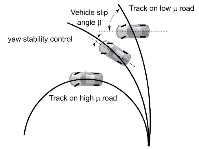
Figure 3‑1 Functioning Yaw Stability Control {Rajamani, 2011 #429}
Vehicle yaw describes the rotational behaviour of the vehicle around it’s vertical axis. In terms of vehicle performance, the vehicle’s yaw behaviour can be used to interpret the vehicles expected trajectory against the intended trajectory. By applying a system to control the vehicle yaw, the directional stability can be maintained. The theory behind controlling the yaw motion of the vehicle is to control the moment produced through the manipulation of the tire-road contact. Controlling the yaw rate of the vehicle strengthens the stability of the vehicle while also allowing the vehicle to perform closer to the performance limits.
There are many different methods to controlling the yaw of a vehicle. All approaches use the same theory which is increasing the moment around the center of gravity by actively controlling the lateral or longitudinal forces distributed by the tires. The lateral dynamics of the vehicle can be controlled effectively by introducing a slip angle to a tire or by varying the distribution of the driving or braking torque.
Stability control systems that focus on yaw rate feedback are being widely commercialized by automotive manufacturers {Sawase, 2006 #280}{Tseng, 1999 #451}{Tseng, 1999 #452}{Liebemann, 2004 #453}{Hoffman, 1998 #454}. Monitoring the yaw is an effective method of retaining control of a vehicle without compromising drivability of the vehicle. Desired yaw rate is interpreted from the steering wheel input and the vehicle velocity and is being utilized in commercial vehicles as a safety measure and to allow the driver to operate closer to the vehicle’s handling limits without losing control.
3.4 Basic Principles of Sideslip Control
Vehicle sideslip (β) is used to describe the heading angle of the vehicle versus the direction of travel for the vehicle. Limiting the vehicle sideslip angle allows for better control as consequently the tires slip angles are limited from reaching saturation{Ahmadi, 2009 #455}.
Though vehicle sideslip is not easy to measure accurately, there are increasing methods for acquiring the sideslip angle of a dynamic vehicle. Reasonable estimations of vehicle sideslip can be estimated with vehicle velocity and lateral acceleration. More accurate estimation can be acquired through the integration of GPS based vehicle velocity vector with the vector of vehicle velocity from the Inertial measurement unit (IMU). Daily et al. {Daily, 2004 #456} describe the error from this method is mainly due to the error of GPS measurement and can be corrected using a velocity error function. The main issue with GPS based measurement is the unreliability in environments where there are tall objects.
Piyabongkarn et al. {Piyabongkarn, 2009 #450} determine other methods of observing the vehicle sideslip angle include the use of optical sensors and dynamic model-based estimations. Also discussed within this article is a new slip angle estimation method which uses a model based estimation combined with a kinematics based estimation. Through experimental implementation, the vehicle sideslip was effectively calculated and provides robust estimation of vehicle sideslip angle through extreme maneuvers.
3.5 Torque Vectoring
Torque vectoring is a term for the distribution of the engine torque to the drive wheels. If a vehicle is turning, the outside wheel travels a percentage more than the inside wheel. By applying more torque to the outside wheels during a turn, the vehicle is more likely to complete the maneuver with more confidence. Companies such as Mitsubishi, Ford, Nissan, ….
Early development of torque vectoring by Mitsubishi motors was to create “a vehicle that anyone can drive safely”. To avoid the brake assisted steering which would reduce the vehicle speed and conflict with the driver’s input, Mitsubishi developed the Active Yaw Control system (AYC) using a “torque transfer mechanism” along side their already developed Active Stability Control (ASC). The result was a torque transfer differential which was applied to only the rear axle of the 4wd vehicle. The system used a feed forward control system to improve the responsiveness of the vehicle by analyzing the driver input steering wheel angle and throttle position. It was coupled with feedback control to monitor the lateral wheel speed difference. Additional systems could maintain control during a drift maneuver and would adjust the gain of the controller by estimating the surface friction coefficient, µ. The system allowed for higher lateral accelerations to be achieved through the use of left/right torque control while improving the control of the vehicle. When in use with the ASC system, the vehicle becomes easier to control, and if the control limits are reached the vehicle is able to recover. [3]
3.6 Active Braking Assist
The use of braking is an effective method of applying a yaw torque in order to either regain stability or increase the yaw rate performance of a vehicle. Many car companies are able to implement an active braking assist with ease because it uses the same hardware as ESC, which is standard in all vehicles sold in North America [4].
Using braking torque to control the yaw motion of the vehicle is different than a braking based ESC as it is not required to be braking to activate. Ghike et al. state that varying the torque by using the brakes are less intrusive while more effective at controlling lateral vehicle dynamics than the ESC while also causing less of a decrease in velocity [5]. By braking the inside wheel of a slip-differential based axle, more torque is sent to the outside wheel, completing the desired torque distribution. As seen in Figure 2 the yaw moment can be applied by braking the inside
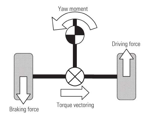
Figure 3‑2: Lateral Braking Control [6]
3.7 Active Steering Assist
Active steering assist describes a system which allows the steering angle to be manipulated by a computer system to adjust for the lateral dynamics of a vehicle. This system also allows for the addition of semi-autonomous systems such as lane assist and emergency steering assist which is useful as control systems have quicker and more precise reaction than the driver [7]. Active steering assist allows the function of path following to the driver while the disturbance adjustments are handled by the control system [8]. Active steering also presents some advantages in terms of vehicle performance as continuous operation steering control can correct the driver when a mistake is made, allowing the limits of the vehicles stability capabilities to be tested with more confidence.
Yutaka et al. proposed a new concept for a robust active rear steering which allows for reasonable performance of the vehicle even if vehicle parameters and/or surface conditions are changed. Using µ-synthesis
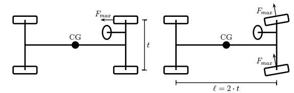
Figure 3‑3: Vehicle Torque while braking front wheel (left) and front wheel steering (right) [7]
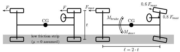
Figure 3‑4: mu-split braking – Balance of torques with active steer
Marino et al. used a decoupling controller which has a feedback of the yaw rate error with velocity dependent yaw damping.
3.8 Rear Axle Steering (RAS)
Rear axle steering is an effective method of controlling the lateral forces generated by the rear tires. The use of RAS is commonly used for decreasing the turning radius of a vehicle at low speeds while reducing tire wear and is found in all types of vehicles ranging from heavy haul trucks, pickup trucks and even sports cars. Rear axle steering can be used at high speeds to reduce the vehicle sideslip. With “steer-by-wire” used for RAS, there are increased possibilities for improving the vehicles dynamic stability. Much like active steering assist, an active rear steering system can improve the lateral dynamics of the vehicle, only separate from the front steering angles. Advanced dynamic stability becomes very useful in heavy vehicles with a high center of gravity as a rollover prevention measure and to increase lateral vehicle performance. Many large trucks already include RAS in order to improve maneuverability at low speed, however Kharrazi et al. {Kharrazi, 2008 #2} suggest there is further development needed in order to achieve improved vehicle yaw stability and responsiveness as well as improved performance over surfaces with different surface friction from left to right.
There are several used methods for controlling the steer angles of the rear axles: Passive rear steering can be implemented into a vehicle by mechanical means, or in methods which the driver does not have any control on. Porsche introduced rear steering using a mechanical linkage, called the Weissach axle, that would reduce the oversteering behaviour by inducing toe-in on the rear axle {Nalecz, 1989 #457}. Though passive steering is not in the scope of this work, it is necessary to appreciate the methods of increasing performance through mechanical approaches. Feedforward control methods generally use the input of the driver to determine the steering of the rear axle. Feedback control methods use the vehicle performance measures to tune the rear steer angle to satisfy the ideal vehicle driving model.
3.9 Feedforward Rear Wheel Steering Control Methods
Feed Forward control methods are an effective means for benefiting from active rear steering by outputting a rear steer angle with reference to the steering input. Knowledge of the vehicle layout and dynamic performance of a vehicle can lead to the optimal tuning of a feedforward controller. Low speed maneuverability can be easily increased using a feedforward controller and the stability of the vehicle is not as crucial to safety at low speeds. A study by Furukawa et al.{Furukawa, 1989 #413} highlights two methods for feedforward control methods.
First is the Zero Side Slip (ZSS) control method. ZSS considers the velocity of the vehicle and the steering input. These inputs are used in a transfer function which was derived by analyzing the 2 degree of freedom bicycle model of the vehicle with front and rear steer angles. To satisfy the zero-sideslip portion of the controller, the sideslip angle in the transfer function is set to zero and the yaw rate portion is eliminated, thus producing a speed dependent ratio gain for the steering angle of the rear axle compared to the front axle.
k=-b-maCrlU2a+mbCflU2
Where a and b represent the distance of the front and rear axles to the center of gravity, respectively,
lis the wheelbase of the vehicle, Cf and Cr are the cornering stiffness of the front and rear tires respectively, and U is the vehicle velocity. This produces a relationship presented in Figure 3‑5.
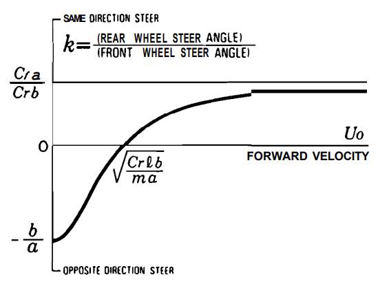
Figure 3‑5 Zero Side Slip (ZSS) Speed Dependent Front to Rear Ratio
The second method reviewed by Furukawa et al. is a purely steering angle dependent relationship. For small input steering angles, the rear wheels steer in the same direction as the front wheels. For larger steering angles, which are more likely to occur at low speed, steer the rear wheels opposite of the front wheels for increased maneuverability. This system enables the low velocity and high velocity steering to be improved without the need to update vehicle speed in the controller. The steer angle dependent RAS system can be seen in Figure 3‑6.
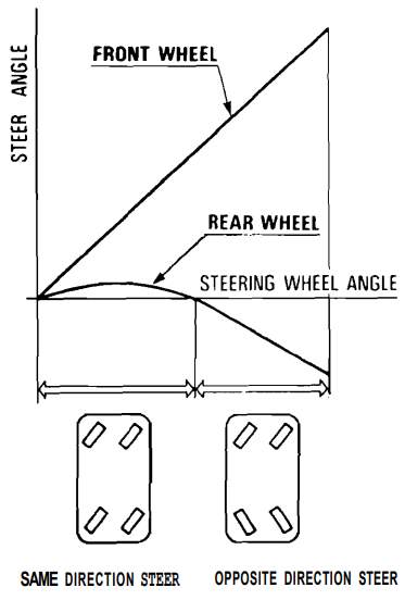
Figure 3‑6 Steer Angle Dependent RAS {Furukawa, 1989 #413}
A study by Fukunada et al. {Fukunaga, 1987 #458} on the Nissan feedforward RAS algorithm, which is similar to the ZSS
Kharrazi et al. [9] observed the effectiveness of rear axle steering on the yaw stability and responsiveness of a heavy truck using MATLAB-Simulink and on a full-scale Volvo truck. The control system focused on split-mu braking and high-speed maneuvers as measures for analyzing vehicle control. The controller steers the rear axle in order to satisfy the driver’s input, or the reference yaw rate. The high-speed steering controller consists of first-order feedforward and a proportional feedback:
δ3=KFF-TFFsδ1+KFB(rref-r)
The split-mu braking controller uses a proportional gain feedforward controller to steer the rear axle to compensate for uneven braking forces on the left and right. This decreases the stopping distance by allowing the ABS system to perform at its capacity without forcing the driver to counter steer. The controller can be described as:
δ3=KpMbrake
The simulations and full vehicle tests conclude the yaw rate error can be reduced by 64% while decreasing the effort needed by the driver. The split-mu braking controller using RAS could reduce braking distance by at least 10% by using a more aggressive ABS system and RAS to maintain the same level of driver input needed as stock vehicle.
Nagai et al. {Nagai, 1997 #443} used a model matching controller (MMC) which applies the state feedback of both the yaw rate and the side slip angle of the vehicle to aid the vehicle in following the ideal dynamic path. MMC method uses linear control theory but proved to be effective at improving the vehicle handling and stability even when the vehicle parameters change. The robustness of a controller is extremely important in a combat vehicle as the vehicle mass and cornering stiffness changes depending on terrain and vehicle purpose.
3.10 Development of simulations {SIMULATIONS SECTION]
Split-mu braking
To verify the effectiveness of split-mu braking controller, Kharrazi et al. used mu_left = 0.15 and mu_right as 0.75 and an initial speed of 50 km/h. [9]
Highspeed turning
Turning radius
Nato Lane change
Robustness against Tire Nonlinearity and Road Condition
To assess the controller for robustness against tire nonlinearity and road condition, Nagai et al. tested the transient response to the different steering wheel angles (from 15 to 45 degrees) on different road friction values (mu = 0.8, 0.6, 0.4). The test used a sinusoidal steering input with one period being 2 seconds. By viewing the yaw rate response against the steering angle input, the controller output can be assessed against the desired output.
References:
[1] U. Kiencke and L. Nielsen, Automotive Control Systems: For Engine, Driveline and Vehicle: Springer-Verlag New York, Inc., 2000.
[2] A. Lie, C. Tingvall, M. Krafft, and A. Kullgren, “The effectiveness of electronic stability control (ESC) in reducing real life crashes and injuries,” Traffic injury prevention, vol. 7, pp. 38-43, 2006.
[3] K. S. Sawase, Yoshiaki, “Application of active yaw control to vehicle dynamics by utilizing driving/braking force,” JSAE Review, vol. 20, pp. 289-295, 1999.
[4] N. H. T. S. A. (NHTSA), “Electronic Stability Control Systems,” in Federal Motor Vehicle Safety Standards vol. 126-49 CFR Parts 571 & 585, ed, 2007.
[5] C. Ghike, T. Shim, and J. Asgari, “Integrated control of wheel drive–brake torque for vehicle-handling enhancement,” Proceedings of the Institution of Mechanical Engineers, Part D: Journal of Automobile Engineering, vol. 223, pp. 439-457, 2009.
[6] K. U. Sawase, Yuichi; Miura, Takami;, “Left-Right Torque Vectoring Technology as the Core of Super All Wheel Control (S-AWC),” Mitsubishi Technical Review, 2006.
[7] J Ackermann, Dr T Bunte, and D Odenthal, “Advantages of Actve Steering for Vehicle Dynamics Control,” 1999.
[8] J. Ackermann and T. Bünte, “Yaw disturbance attenuation by robust decoupling of car steering,” Control Engineering Practice, vol. 5, pp. 1131-1136, 1997.
[9] S. Kharrazi, M. Lidberg, P. Lingman, J.-I. Svensson, and N. Dela, “The effectiveness of rear axle steering on the yaw stability and responsiveness of a heavy truck,” Vehicle System Dynamics, vol. 46, pp. 365-372, 2008.
Cite This Work
To export a reference to this article please select a referencing stye below:
Related Services
View all


Related Content
All TagsContent relating to: "Mechanics"
Mechanics is the area that focuses on motion, and how different forces can produce motion. When an object has forced applied to it, the original position of the object will change.
Related Articles

DMCA / Removal Request
If you are the original writer of this dissertation and no longer wish to have your work published on the UKDiss.com website then please: