Effect of Total Disc Replacement on Adjacent Inferior Intervertebral Disc
Info: 10740 words (43 pages) Dissertation
Published: 9th Dec 2019
Tagged: MedicineSurgical Studies
Contents
1.2). the Anatomy of Vertebrae
1.3). Medical Biomechanics of the Spine
1.3.4). Total Disc Replacement (TDR)
1.3.5). the Outcomes of the Surgery
1.4). the Numerical Modeling Software
3.1). Geometry and Material Properties for Modeling
3.1.4). Vertebral Endplate (VE)
3.1.5). the Summary of Material Properties of TB, CB and VE
3.1.7). Artificial Intervertebral Disc (AID)
3.1.8). the Summary of Material Properties including NP, AG and AF
3.1.9). M6-L Material Properties
3.1.10). Summary of the modeling element and properties
3.2). Modeling and Interactions
3.2.1). Cortical Bone (CB), Trabecular Bone (TB) and Vertebral Endplate (VE)
3.2.2). Intervertebral Disc (IVD)
3.2.3). Artificial Intervertebral Disc (AID)
3.3). Boundary Condition and Loadings
3.3.2.2). Bending Moment and Shear Load
7). Research Significance and future work
1). Introduction
1.1). Background
Low back pain is a worldwide health problem; 70-80% of people will experience low back pain at some point in their lives. The vast majority of the people who have a low back pain will be better without any medical treatments (Orthoinfo, 2018). However, if the symptom of the back pain could not be naturally assuaged, the surgery might be an option.
Currently, two surgical alternatives are available: spinal fusion and a total disc replacement (TDR). Several studies proved that TDR is superior to spinal fusion because it can provide a higher physiological range of motions and has low complications after the surgery (NICE, 2009). However, the benefits of TDR is more long-term which cannot be properly investigated in less than 10 years follow-up. Therefore, TDR is still not prevalent in the global medical field and has a very limited literature (Vital, 2014).
In this study, the author aims to investigate the effect of TDR on an adjacent inferior intervertebral disc by analyzing the stress-strain distribution.
1.2). the Anatomy of Vertebrae
The low back spine or lumbar consists of the bony structure separated by the intervertebral disc (IVD), and it comprises of five vertebras called L1 to L5, illustrated in Fig 1. Below L5 is the sacrum section, which is separated into five segments (S1-S5) that are fused together.
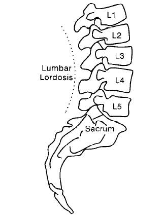
Fig 1: Side view of L1 to L5, (S.H. Hwang & Y.E. Kim, 2009)
1.2.1). Lumbar Vertebrae
The lumbar section consists of five separate vertebral bodies. They are named as the first, second, third, fourth and fifth lumbar vertebrae. Viewed from above and below, the vertebral body is more or less kidney-shaped, illustrated in Fig 2. The dorsal surface is slightly concave or flat; the superior and inferior surfaces are dedicated to support immense longitudinal loads (Liem et al., 2006).
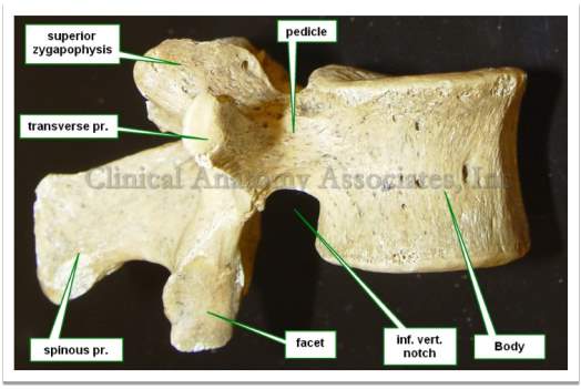
Fig 2: Vertebral features and vertebral body in inferior and lateral view (Klein, 2016).
The internal vertebral body is classified into two layers: cortical and trabecular bone. The cortical bone is a shell surrounding a spongy bone, trabecular bone, illustrated in Fig 3. The design of cancellous trabecular bone provides the living with advantages. Although the solid element of a typical bone is strong at bearing the lateral loads, the solid element is heavy and not suitable for various types of loads such as bending and torsion. Another advantage is the convenience to supply the blood into an entire of the vertebral body to keep the bone alive (Bogduk &Baker, 14).
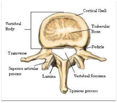
Fig 3: Segment of the vertebral body (Aslan. et al., 2009)
1.2.2). Intervertebral Disc
An intervertebral disc consists of two main parts including nucleus pulposus (NP) and annulus fibrosus; both have the main function to provide the structural stability and flexibility, showed in Fig 4. The nucleus puluposus is mainly composed of proteoglycan, water and collagen type II located at the center of the disc (Choi and Harfe, 2011). NP can take up 30-50% of a cross-sectional area of the disc and the main function is to distribute the load uniformly across the spinal disc (Miele et al., 2012). The proteoglycan in NP provides the osmotic properties enabling NP to maintain the height and properly withstands the compressive loads (Watanabe et al., 1998).
Each disc has a tough outer wall called the annulus fiber (AF), oriented at an average of +/- 30° with respect to the transverse plane. AF allows the surrounding vertebrae to effectively bend and twist (Miele et al., 2012). Additionally, it prevents NP from herniating to the neural cords, which could result in low back pain.
1.2.3). Vertebral Endplates
The plates are located at the upper and lower portions of each IVD, illustrated in Fig 4. The end plate is considered as a thin and soft layer of hyaline cartilage that lies between the vertebral bodies (Moore, 2000). The cartilage component of the end plates is reinforced by a network of collagen fibrils to support the stability of a structure (Maroudas et al. 1975). In the adult case, the end plate is less than 1 mm thick and are varied across its cross-section; commonly, the thinnest part of the end plate is located at the middle above NP (Robert et al., 1989).
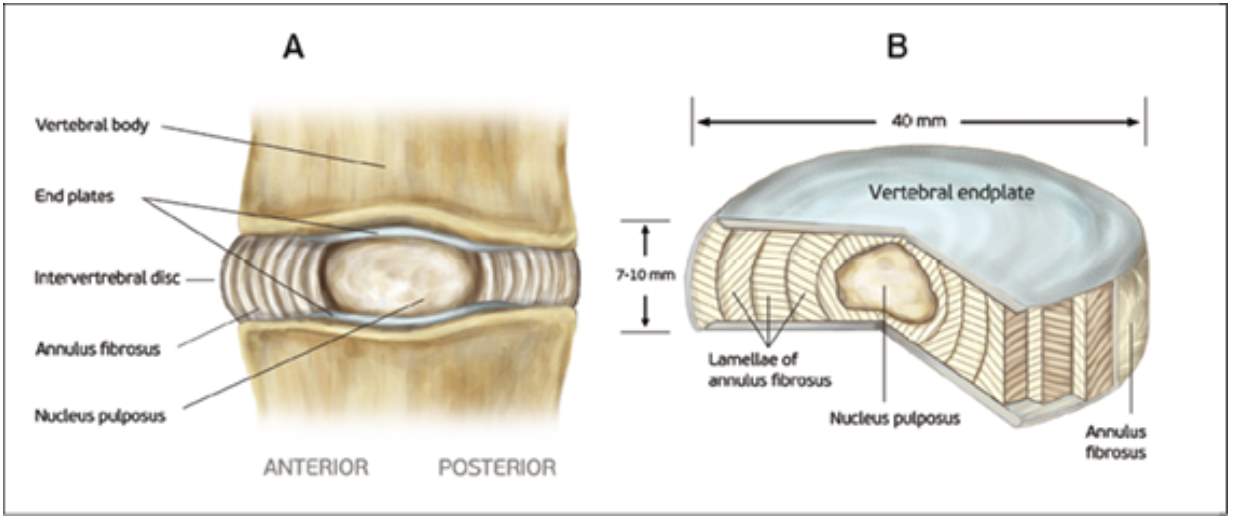
Figure 4. Human intervertebral disc and vertebral endplate (Tomaszewski et al., 2014)
1.2.4). Spinal Ligaments
Ligaments are fibrous bands of tissue, which significantly contributes to the biomechanical stability; they support the load under tension and can buckle under the compression. Excessive movement such as hyper-extension and hyper-flexion may be restricted to prevent the damage on the vertebrae (Bridwell,& Rodts, 2018). There are three more important spinal ligaments including anterior longitudinal ligament (ALL), posterior longitudinal ligament (PLL) and ligamentum flavum, illustrated in Fig 5. The spinal ligaments assist three main functions. First, they permit motion and help orient the vertebrae without muscle recruitment. Second, ligaments protect the spinal cord by restricting spinal motion segment movement to within specific ranges. Third, they absorb energy and protect the spinal cord during rapid motions (Garfin et al. 2011).
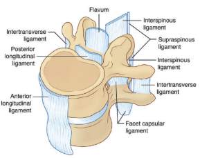
Fig 5: Ligament of the spine (White & Panjabi, 1990.)
1.3). Medical Biomechanics of the Spine
1.3.1). Low Back Pain
Recently, back pain is a very common health problem, and around 10% of the patient become chronically disabled (Urban &Robert, 2003). It also put the economic burden to each society; in the United States, the total cost related to this condition had exceeded $100 billion per year (Crow & Willis, 2009). Although the cause of low back pain is unclear, the dysfunction of IVD is an important source causing the low back pain.
Additionally, the back pain can arise from the nature of biological changes, disc degeneration (DD), showed in Fig 6. The cell inside the disc progressively degenerates its capacity when ages. DD alters the disc height disturbing the overall mechanic of the vertebral column, muscles and ligaments (Urban &Robert, 2003). Moreover, the degeneration disrupts the stress distribution over the disc resulting in the more pressure being put on the root nerve, which could lead to back pain (Adams et al., 1996).
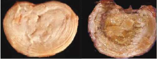
Fig 6: Normal intervertebral disc and degenerated intervertebral disc (Urban &Robert, 2003)
1.3.2). Surgical Treatment
According to Hahne et al, the surgical operation of the lumbar disc should be avoided (2010). However, if nonsurgical treatments have failed to improve the patient’s symptoms and the pain hinders the patient to complete his daily activities for more than two months, then surgery may be an option to alleviate the back pain (Spivak, 2018; Bogduk &Andersson, 2009; Rothoerl et al., 2002). Nowadays, two general types of back surgery are available: spinal fusion and TDR, illustrated in Fig 8.
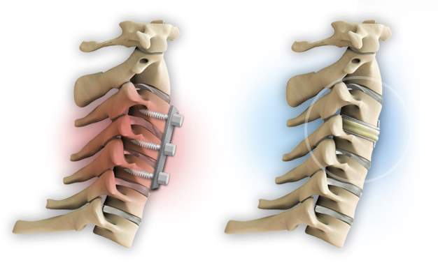
Fig 8. Spinal fusion on the left and TDR on the right (Anon, 2018)
1.3.3). Spinal Fusion
The traditional approach for the low back pain is the spinal fusion. The operation unites two or more vertebral bodies together. The objective of this operation is to restrict the vertebral movement that is presumed to be the pain generator (Chou, 2018). The surgery includes the placement of a bone graft between the vertebrae, and an additional cage is implemented to hold the bone in place. According to Fritzell et al., the fusion technique is more effective than nonsurgical therapy at two years follow up. From overall patients’ reports by questionnaires, the patients’ satisfaction was significantly higher in the surgical group, with 63% reporting to be improved compared with 29% in the nonsurgical group, illustrated in Table 1 (2001). However, the spinal fusion will reduce the range of motion, extended recovery time, and residual pains are associated with the fusion location. To eliminate those disadvantages of the spinal fusion, TDR is creatively invented.
| Surgery Fusion | Non-surgery | |
| % | % | |
| n | 195 (missing 6) | n=62 (missing 1) |
| Much better | 28.8 | 14.5 |
| Better | 33.8 | 14.5 |
| Unchanged | 23.6 | 45.2 |
| Worse | 13.8 | 25.8 |
| Total | 100 | 100 |
Table 1: Patient overall rating of the result after two years (Fritzell et al, 2001)
1.3.4). Total Disc Replacement (TDR)
Unlike the spinal fusion, TDR uses an anterior approach to insert the artificial disc between the vertebral bodies. The artificial disc substitutes both NP and annulus fibrous with various material properties, showed in Fig 7.
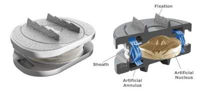
Fig 7: Artificial disk replacement (Jenis, 2005) and M6-L artificial disk (Anon)
The TDR surgery is design to remove the damaged disc and provides the patient with an artificial intervertebral disc, which gives the same range of motion. Through the studies of this procedure, the National Institute for Health and Clinical Excellence (NICE) agreed that this procedure is safe and effective work (2009). In the study of 236 patients by NICE, 161 were treated with artificial disc replacement and 75 with spinal fusion. Three months after the surgery, the patients who had the TDR with 87% reporting the improvement in the quality of life (measured by questionnaires), while the patient with spinal fusion experience an improvement of 70% (NICE, 2006). A study by David T et al. concluded that the patient with artificial disc replacement with 82% had an either excellent or good in the surgical outcome, and 89.6% can return to work (2007). Lastly, Vital et al. concluded that TDR had demonstrated non-inferiority to spinal fusion (2014).
1.3.5). the Outcomes of the Surgery
After TDR surgery, most patients can expect to recover from the lower back pain in weeks to months following the surgery. Several studies show that the disc replacement improves the conditions of low back pain, but does not completely eliminate the pain (Orthoinfo, 2018).
1.4). the Numerical Modeling Software
Recently, Finite Element Analysis (FEA) has been used for testing the hypotheses in biomechanical subjects; it has an ability to model the complexed shape of biological objects such as skull and vertebra (Ross, 2005). Additionally, several papers provide with loading conditions and material properties to create an accurate model compared to vivo strain data. As the numerical simulation becomes reliable, FEA will significantly reduce the time and cost of biomechanical investigations.
The FEA software, ABAQUS, is selected to achieve the result of this current study. In many studies, ABAQUS has been prevalently used to analyze linear behavior and small displacement in the vertebrae (Shirazi & Ayatollahi., 2014; Little et al., 2013 Ferguson et al., 2003).
2). Literature Review
In 2004, Swanson et al. studied the effects of an interspinous implant on intervertebral disc pressure, illustrated in Fig 8. The research used cadaver lumbar specimens (L2-L5) and placed the implant between L3-L4. Then, loads of standing, flexion and extension were applied to investigate the stress changing in an adjacent intervertebral disc. The result showed that the implant did not significantly change the other IVD pressures, and there was no relation between an accelerated disc degeneration and implant device. This topic stimulates the author’s concern to this current study whether the TDR changes the other intact IVD in stress and strain distribution.
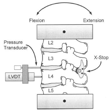
Figure 8: Testing configuration with an interspinous implant
In 2014, Chen &Li studied the effect of cervical artificial disc replacement on adjacent inferior intervertebral disc stress. Spinal fusion and disc replacement between C5 and C6 were implemented in the fresh cervical spines (C3-T1). Then, they applied the axial load ranging from 25 to 150N. Finally, stresses of the intervertebral disc between C6 to C7 is recorded. This research gave two conclusions. First, the spinal fusion can significantly affect the adjacent inferior intervertebral stress. Second, no obvious effect of the cervical artificial disc on the adjacent inferior intervertebral stress.
Lumbar total disc replacement (LTDR) have been introduced for about 10 years. In the study of the total disc replacement in lumbar degenerative disc diseases, and it concluded that the clinical result of LTDR remained unsettled and needed longer time to follow up to confirm no new complications could arise (Park, 2014).
Overall, there is a research gap to study the effect of a lumbar artificial disc replacement on an adjacent inferior intervertebral disc due to the combination of activities’ loads.
3). Research Method
3.1). Geometry and Material Properties for Modeling
3.1.1). Vertebral Body
Zhou et al. provided the precise dimension of the lumbar vertebrae and IVD by utilizing computed tomographic (CT) images from the patient with low back pain, illustrated in Fig 9 (2000). For this current study, the author adopts an approximate vertebral body height of 50mm (both anterior and posterior) and the intervertebral disc height of 11mm. The overall dimension of the vertebral body in the XY plane is defined by a kidney-shaped in Fig 10 (Lavaste et al., 1992). Several studies are unclear in describing the way to sketch the VB, therefore, the author outlines the VB into spline curves in ABAQUS sketching software.
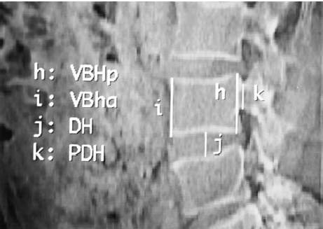
Fig 9: the Vertebrae by CT scan (VBHp vertebral body height posterior, VBHa vertebral body height anterior, DH disc height and PDH pedicle height)
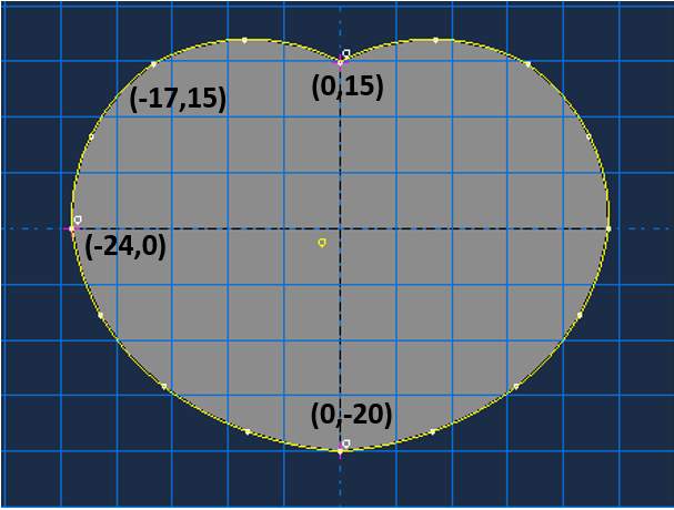
Fig 10: Sketch of the vertebral body (kidney shape) in mm
Several works provided the vertebral body with a varied cross-sectional area. Zhou et al. found the mean of the cross-sectional area, which ranged from 1,318-1,665 mm2 (2000). In 2005, Fatima et al. performed the study of intervertebral disc on five patients aged 65-75 years for L2-L5 (2015); the study proposed the cross-sectional area of 1,739 mm2 for L2-L3 and 1,951 mm2 for L4-L5. In this current study, the author found the cross-sectional area of the model is 1,422 mm2, which reasonably related to Zhou et al. result.
3.1.2). Cortical Bone (CB)
The vertebral body mainly consists of trabecular and cortical section. Many studies modeled the trabecular bone as an isotropic material and continuum solid element with the Young’s modulus (E) of 12,000 MPa and the Poisson’s ratio (V) of 0.3 (Asgharzadeh & Ayatollahi., 2014; Pitzen et al., 2001; Goel et al., 1995). However, the recent research by Zhu et al. offered orthotropic properties: E, shear modulus (G) and V in three-dimensions. For cortical bone, Ex = 140 MPa, Ey = 140 MPa, Ez = 200 MPa, Gx, Gy, Gz = 48.3 MPa, Vxy = 0.45, Vxz = 0.32 and Vyz = 0.32 (2018). All material properties are described in Table 2.
3.1.3). Trabecular Bone (TB)
The cortical bone serves as a protective layer on the trabecular bone. Zhou provided the cortical thickness of L3, L4 and L5 with the range around 3 mm (2000). A majority of studies modeled the cortical bone as a continuum solid element with isotropic materials (Asgharzadeh &Ayatollahi., 2014; Borkowski et al., 2012; Ferguson et al., 2004; Goel et al., 1995; Lavaste et al. 1992). In contrast, Castro et al. represented the cortical bone as a hyperelastic solid, which utilized Moonney-Rivlin models to predict the behavior of nonlinear and incompressible material like rubber (2014). Other authors modeled the cortical bone as a shell element with isotropic (Little et al., 2013; Wagnac at el., 2011; Geisler at el., 2000). Lastly, Zhu et al. modeled the cortical bone as an orthotropic material with different E, G and V in three-dimensions; all material properties are showed in Table 2 (2018).
3.1.4). Vertebral Endplate (VE)
The vertebral endplate (VE) located at the upper and lower of the VB in Figure 4; the function of the VE is to link and transfer the loads between VB and IVD (Lotz et al. 2013). A majority of the literature modeled the VE with E = 23.8-24 MPa and Poisson’s ratio of 0.4 (Zhu et al., 2018; Ueno et al., 2005; Glema et al., 2004). However, Castro et al. offered a Mooney Rivlin model with permeability values to represents the non-linear behavior of the VB, like rubber (2014).
3.1.5). the Summary of Material Properties of TB, CB and VE
Table 2: Material Properties of TB, CB and VE
| Authors | Trabecular Bone | Cortical Bone | Vertebral Endplate | |||||||||
| E | v | C10 | C01 | E | v | C10 | C01 | E | v | C10 | C01 | |
| Zhu et al., 2018* | orthotropic materials | orthotropic materials | 24 | 0.4 | – | – | ||||||
| Asgharzadeh &Ayatollahi., 2014 | 10 | 0.2 | – | – | 12,000 | 0.3 | – | – | – | – | – | – |
| Castro et al., 2014 | – | – | 41.67 | 0 | – | – | 3846.15 | 0 | 1 | 0 | ||
| Little et al., 2013 | 140 | 0.2 | – | – | 11,300 | 0.2 | – | – | – | – | – | – |
| Borkowski et al., 2012 | 400 | 0.4 | – | – | 12,000 | 0.35 | – | – | – | – | – | – |
| Wagnac et al., 2011 | 400 | 0.3 | – | – | 14,500 | 0.3 | – | – | 12 | 0.4 | ||
| Ferguson et al., 2004 | 100 | 0.2 | – | – | 10,000 | 0.3 | – | – | 5 | 0.17 | – | – |
| Glema et al., 2004 | – | – | – | – | – | – | – | – | 23.8 | 0.4 | ||
| Pitzen et al., 2001 | 25 | 0.2 | – | – | 12,000 | 0.3 | – | – | – | – | – | – |
| Goel et al., 1995 | 100 | 0.2 | – | – | 12,000 | 0.3 | – | – | – | – | – | – |
| Lavaste et al. 1992 | 100 | 0.2 | – | – | 12,000 | 0.3 | – | – | 500 | 0.4 | – | – |
| Ueno &liu, 1987 | – | – | – | – | – | – | – | – | 23.8 | 0.4 | ||
*Zhu et al., orthotropic properties
– For cortical bone, (Ex, Ey and Ez = 11 300, 11 300, 22 000 MPa), (Gx, Gy, Gz = 3800, 5400, 5400 MPa), (Vxy, Vxz, Vyz =0.48, 0.2, 0.2).
– For trabecular bone, (Ex, Ey, Ez = 140, 140, 200 MPa), (Gx, Gy, Gz = 48.3, 48.3, 48.3 MPa), (Vxy, Vxz, Vyz =0.45, 0.32, 0.32).
3.1.6). Intervertebral Disc
The IVD generally composes of three main parts: NP, annulus ground (AG) and annulus fiber (AF), showed in Fig 11, and IVD cross-sectional area is closely equal to VB. A majority of the studies modeled the NP as a non-linear incompressible solid and incompressible fluid, which was being compressed and expanded to the AF and AG (Glema et al., 2004; Little et al., 2013; Ueno et al., 1987). A non-linear behavior could be described by the hyperelastic Mooney-Rivlin model, C10 and C0 parameter, in ABAQUS inputs (Ibarz et al., 2014; Castro et al., 2014; Ferguson et al., 2004; Goel et al., 1995; Lavaste et al., 1992). In contrast, other authors considered the NP as a linear isotropic material with a range of Young’s modulus of 1 to 2, while the poison’s ratio was around 0.499 or 0.5 (Zhu et al., 2018; Wagnac et al., 2011).
For AG, most authors considered proteoglycans of the AG as a linear isotropic material with the Young’s modulus range of 2 to 4.5 MPa and poison’s ratio of 0.17 to 0.45. In contrast, Little et al. modeled AG as an incompressible solid with the Mooney-Rivlin parameter of C10 = 0.7 and C0 = 0.2 (2013).
On the surface of AG, there is an alternating collagen fiber called AF (tensile only material) separated into five layers of fibers; every four concentric rings of a ground substance contains two annulus fibers oriented at ±30° to the transverse plane (Kim et al., 2015). To model AF, the rebar reinforcements with a diameter of 0.8mm are represented as two trusses element embedded on the surface of annulus ground (Denoziere & Ku, 2006). However, the AF orientation is unclear; Lee et al. claimed the fiber orientations had a mean between 24° and 45° from the horizontal plane (2011). Dittmar et al. claimed that the orientation of the fiber was varied from ∼30° at the outer surface to ∼45° at the inner surface, and increased circumferentially from the anterior to the posterior section from ∼30° to ∼50° (2016). For this current study, the truss orientation is between ∼25° and ∼34°.
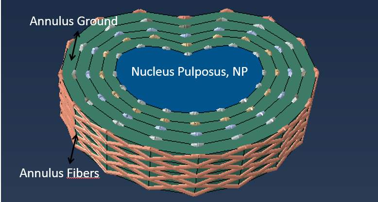
Fig 11: IVD with annulus ground surrounded by annulus fibers at varied orientations
3.1.7). Artificial Intervertebral Disc (AID)
An AID is designed to provide the same physiological motions as the natural disc, which offers all six degrees of freedom. Since the detailed geometry of AID (model M6-L) is commercially disclosed, the author will model M6-L with an approximate dimension with different materials properties. Modeling M6-L has to be treated with cares because of the singularity issue in FEA; the stress at the singularity point will not converge causing the stress in that area goes to infinity, which might cause an overall result inaccurate.
Many possible solutions can be implemented to deal with the singularity (Acin, 2015). First, the mesh can be refined to the smaller to capture the stress. Second, the sharp edge should be avoided. Third, an elastoplastic assumption must be applied to prevent the stress to infinity.
The majority of the studies represented the AID material as an isotropic behavior. Geisler et al. utilized titanium with Young’s modulus of 110,000 MPa and Poison’s ratio of 0.36 (2000). Lee et al. modeled two types of AIDs including Prodic-C and Mobi-C with CoCr alloy and Ultra high Molecular weight polyethylene; Young’s modulus is 210,000 MPa and 3,000 MPa respectively, and those two materials have the same poison’s ratio of 0.3 (2011). Lastly, Linde proposed an isotropic material for the implant device with chrome cobalt and molybdenum; this AID had Young’s modulus of 200,000 MPa and poison’s ratio of 0.3 (1994).
3.1.8). the Summary of Material Properties including NP, AG and AF
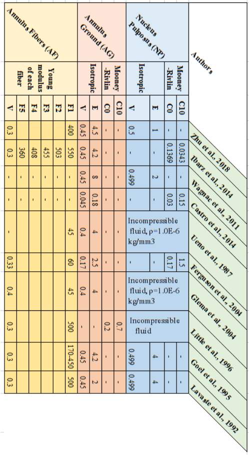
Table 3: the Summary of IVD properties
3.1.9). M6-L Material Properties
The author tries to duplicate M6-L based on the actual model, which the SpinalKinetics shows the general dimension of the model in a commercial website (Orthoinfo, 2018). M6-L mainly consists of three components with three material properties, illustrated in Figure 15. On the top and bottom parts of M6-L, there is a titanium plate 1 mm thickness with Young’s modulus of 110GPa and Poisson’s ratio of 0.35 (Pérez-Pevida et al., 2016). The second layer is an Ultra-high-molecular-weight polyethylene (UHMWPE) with the thickness of 25 mm; Zdero et al. studied the biomechanical effect on UHMWPE giving the Young’s modulus of 0.7-1 GPa and Poisson’s ratio of 0.4 (2014). Lastly, a viscoelastic polymer is located at the middle of the model with the thickness of 4 mm. In addition, there are no clear values for Young’s modulus and Poisson’s ratio in biomechanics studies. Chan & Ngan measured an elastic modulus of viscoelastic materials by utilizing rate-jump tests giving an approximate Young’s modulus ranging from 776-860 MPa when the stresses at jump ranged from 0.5-5MPa (2010). Since normal human activities never exceed the compressive load of 5MPa, adopting Young’s modulus of 800MPa is reasonable. From the parameter study by flat punch test, Zhang concluded the Poisson’s ratio of sphere viscoelastic polymer is 0.13 (Yu et al., 2017). However, viscoelastic polymer Young’s modulus and Poisson’s ratio might contribute to the overall error because the testing conditions for both E and V are set outside the biomechanics used. Finally, M6-L was set up at the center of the VB to replicate the actual location of the implant surgery.
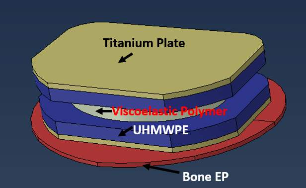
Fig 12: The sketch of M6-L model and each color shows the different materials
3.1.10). Summary of the modeling element and properties
Table 4: the summary of all selected properties
| Vertebral Body | E (MPa) | V | |
| Trabecular Bone | 400 | 0.2 | |
| Cortical Bone | 12,000 | 0.3 | |
| Endplate | 24 | 0.4 | |
| Intervertebral Disc |
NP | 2 | 0.499 |
| AG | 4.2 | 0.45 | |
| AF | 550(outside), 503, 455, 408, 360 (inside), V= 0.3 | ||
| Artificial Disc
|
Titanium | 110,000 | 0.35 |
| UHMWPE | 8,000 | 0.4 | |
| Viscoelastic Polymer | 800 | 0.13 | |
Shell element (S4R) is used to model the cortical bone. AF is truss element (T3D2). Otherwise, other parts are solid continuum element (C3D8).
3.2). Modeling and Interactions
3.2.1). Cortical Bone (CB), Trabecular Bone (TB) and Vertebral Endplate (VE)
First, the geometry of TB is sketched, illustrated in Figure 10. Then, the model is duplicated into three models (L3, L4 and L5) with three different heights (25, 50 and 25 mm). Second, the vertebral endplates are created at the top and bottom of each TB with the same dimension as TB but the height of VE is 0.8 mm. Third, the shell element (S4R) of the cortical bone is added to all surface area with the thickness of 3 mm. Finally, the material properties and element types were assigned.
3.2.2). Intervertebral Disc (IVD)
IVD is sketched with the same dimension as TB with the height of 11mm, but the line between the sketched nodes is straight, illustrated in Fig 11. Then, IVD is partitioned into five layers: one at the center is NP and four layers are AG. The distance between each AG is 2.5 mm. From ABAQUS result, NP takes 38% of a cross-sectional area of the IVD. Finally, the material of NP and AG are assigned with the element type of C3D8 for both AG and NP.
For annulus fibers, the trusses (T3D2) with different length are created, but they have the same diameter of 0.8mm. On each layer, it consists of 64 double-trusses and the orientations are between ∼25° and ∼34°. After that, the trusses are embedded with the IVD to share the same node.
3.2.3). Artificial Intervertebral Disc (AID)
The detailed dimension is commercially disclosed but the commercial website does give general dimensions and properties of AID to model M6-L; therefore, the sketch and material properties were limited to what Spinalkinetic Company provides, illustrated in Fig. 12.
3.2.4). Idealized Artificial Intervertebral Disc (IAID)
The difference between AID and IAID is the shape. IAID keeps the same dimension as IVD, but the difference in materials is applied. The introduction of IAID will help the author to investigate the effect of the changing shape in an implant disc.
3.2.5). Modeling (Model I to Model V)
To study the effect of AID at L3/4 on an intact IVD at L4/5, five models are introduced. The complexity of the model will incrementally add up from Model I to Model V. Starting with simple model will help the author investigating how small component affect the stress-strain distribution of IVD at L4/5, which will discuss later in loading protocol section. In Model I, the Lumbar (L3-L5) is created without an implant, and the truss is not implanted in IVD. In Model II, the model is the same as Model I, but IVD at L4/4 is substituted with IAID. In Model III, it increased Model II complexity by using AID instead of IAID. In model IV, it is as same as Model I, but the truss elements is implanted in both IVDs. In Model V, it is the most complexed Model; the AID is introduced at L3/4 and the truss elements are at both IVDs. All models are exemplified in Fig. 13.
Fig. 13. the Images of each model
3.3). Boundary Condition and Loadings
3.3.1). Boundary Condition
The boundary condition is applied at the endplate of L5. The translations of six-degrees of freedom on the bottom endplate are restricted. A majority of studies commonly applies the same boundary condition at the bottom of the model for experimental studies. However, this boundary condition might not be realistic; it should address whether the boundary condition should be applied at the vertebral body or else because some muscles and ligament might hinder the translations as well. However, this boundary condition does not limit this current study because the model does not aim to provide the exact results of the stress-strain distribution and local displacement; it aims to compare the effect of an implant disc on the intact IVD. Therefore, as long as the author controls the same boundary conditions for an entire study, the result of implant and intact IVD can be compared.
3.3.2). Loadings
Shirazi-Afi et al. determined the spinal loads at each level of lumbar in standing postures with and without an external 200N load (2004). The positions of the loads are either in front of the body or on the sides. The result of the load distribution is illustrated in Table 5.
Table 5: the loads at different levels and postures
| Level
|
P = 0N | P=200N, held on sides | P=200N, held in front | ||||||
| Comp. Loads | Shear | Moment | Comp. Loads | Shear | Moment | Comp. Loads | Shear | Moment | |
| N | N | Nm | N | N | Nm | N | N | Nm | |
| L1 | 323 | -77 | -5.5 | 533 | -119 | -5.3 | 549 | -227 | -7.4 |
| L2 | 344 | -88 | -2.6 | 556 | -126 | -0.9 | 566 | -233 | 1 |
| L3 | 376 | -23 | -0.1 | 594 | -16 | 1.2 | 622 | -110 | 5.9 |
| L4 | 400 | 7 | 0.4 | 625 | 59 | 2.5 | 662 | -2 | 10.8 |
| L5 | 404 | 147 | -0.8 | 599 | 273 | -1.3 | 638 | 268 | 8.2 |
*Shear force: positive in anterior direction; Moment: positive in extension direction
Since this current study focuses on only L3-L5, the loads will be applied at those three specific areas (L3-L5) with compressive loads, shears and moments.
3.3.2.1). Compressive Load
All compressive loads will be transformed into the pressure acting on an entire EP surface area, illustrated in Fig 14. In this study model, the surface area is 1,422mm2. Therefore, the compressive pressure is a load at each level of lumbar divided by the cross-sectional area.
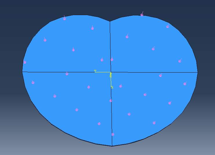
Fig 14: the compressive pressure (pink arrow) evenly applied on the top surface of EP
3.3.2.2). Bending Moment and Shear Load
Bending moments in flexion and extension can be represented as a local pressure. The anterior pressure will produce the flexion bending moment and vice versa, as illustrated in Fig 14. To define the pressure at the anterior part that creates flexural moment, first, define the centroid of the EP which ABAQUS gives the centroid of (x,y) = (0 mm, 0.0089mm). Second, find the centroid of an anterior part (the pink region in Fig 14) which ABAQUS gives (x, y) = (0 mm, 7.27mm). Third, find the moment arm, which is the distance between the centroid of the EP and the centroid of an anterior section. The pressure then is assumed to act like a point load at the local centroid to create moment. Therefore, the pressure can be calculated from the equation, Bending moment (N-m) = Pressure (MPa) * Area (mm2|) x Moment Arm (mm). The same concept is applied to the extensional moment to create the extensional pressure. For shear loads, the yellow arrows in Fig 15. represent the direction of shear loads which can be either anterior or posterior sections.
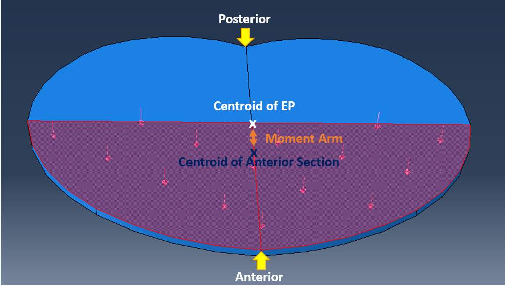
Fig. 15: Anterior pressure that creates flexional moment
3.4). Loading Protocols
3.4.1). Phase I, the study of loading components (Model I)
There are five loading components in three activities: compressive load, anterior &posterior shear load and flexional &extensional moment. Since five conditions can affect an intact IVD between L4/5 differently, understanding what each component disturb the stress-strain distribution is important. Therefore, five sample loads are created: compressive load of 400N, flexional &extensional moment of 1Nm, and anterior &posterior shear load of 50N. Then, apply five loads individually on Model I at L3, L4 and L5 level to investigate the effect of each load component, illustrated in Fig 16. Finally, run the model with the loads from three activities.
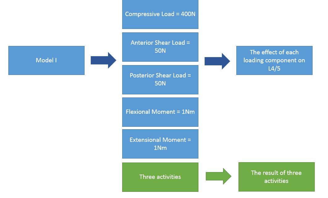
Fig. 16: the Study of loading components
3.4.2). Phase II, the material properties study (Model II)
The idealized implant disc has the same dimension as IVD, but material properties are very rigid based on M6-L. Running the model with three activities will help understanding what material properties does on the stress-strain distribution on an intact IVD at L4/5, illustrated in Fig. 17.
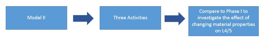
Fig. 17: the Study of material properties
3.4.3). Phase III, the implant shape study (Model III)
The actual M6-L is introduced between L3/4. The implant device has the same material properties as Model II, but an overall dimension is changed. Then, three activities’ loads are applied. The goal of phase III is to comprehend the effect of changing shape on an intact IVD at L4/5, illustrated in Fig. 18. Lastly, the stress singularity needs to be checked in this phase to prevent an infinity stress on the local area.
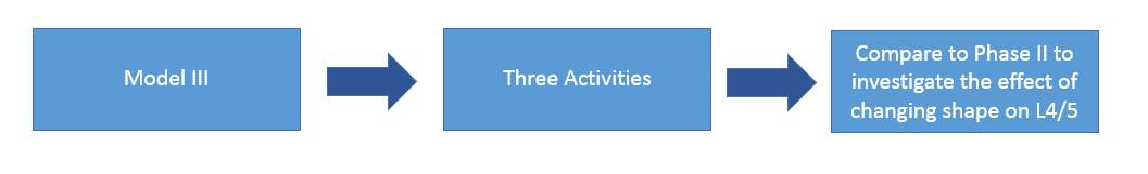
Fig. 18: the Study of an implant shape
3.4.4). Phase IV, the effect of introducing truss on IVD (Model IV)
The trusses are introduced on IVD at L3/4 and L4/5. Five load combinations in Phase I will be applied to understand what each loading component affects the stress-strain distribution on a trussed IVD at L4/5. Then, three activities loads will be applied to get an overall result, which will be compared with the three activities’ result from Phase I.
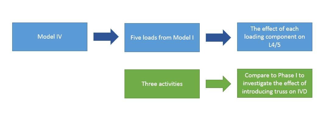
Fig. 19: the effect of truss on IVD
3.4.4). Phase V, the study of M6-L TDR (Model V)
The final model is introduced in model V and being run with three activities’ loads. The overall result will be compared to Phase IV to articulate whether the M6-L TDR at L3/4 affects an intact IVD at L4/5 on stress-strain distribution which can lead to an excessive local displacement.
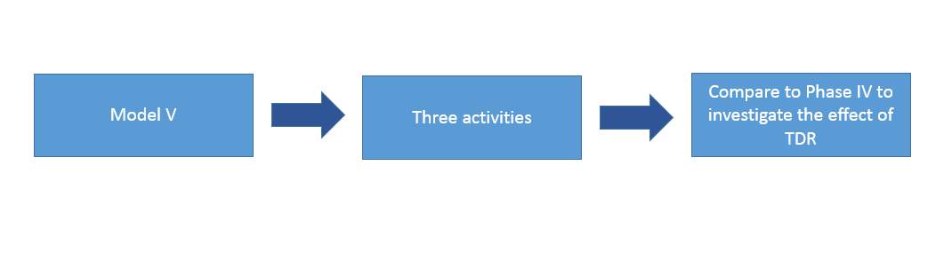
Fig. 20: the effect of TDR
4). Result
5). Discussion
6). Summary &Conclusion
7). Research Significance and future work
References
Orthoinfo.aaos.org. (2018). Artificial Disk Replacement in the Lumbar Spine – OrthoInfo – AAOS. [online] Available at: https://orthoinfo.aaos.org/en/treatment/artificial-disk-replacement-in-the-lumbar-spine/ [Accessed 21 Jul. 2018].
Tidy, C. (2016). Back Pain | Lower Back Pain | Treatment and Causes. [online] Patient.info. Available at: https://patient.info/health/back-and-spine-pain/lower-back-pain [Accessed 21 Jul. 2018].
Kerkar, P. (2018). Intervertebral Disc Herniation|Types|Symptoms|Treatment|Diagnosis|Prevention. [online] ePainAssist. Available at: https://www.epainassist.com/back-pain/intervertebral-disc-herniation [Accessed 21 Jul. 2018].
S.H. Hwang & Y.E. Kim. (2009) Measurement of Lumbar Lordosis using Fluoroscopic Images and Reflective Markers.
White, A.A. & Panjabi, M.M., 1990. Clinical biomechanics of the spine, Philadelphia: Lippincott.
Jenis, L.G., 2005. Artificial Disk Replacement in the Lumbar Spine – OrthoInfo – AAOS. Clavicle Fracture (Broken Collarbone) – OrthoInfo – AAOS. Available at: https://orthoinfo.aaos.org/en/treatment/artificial-disk-replacement-in-the-lumbar-spine/ [Accessed July 21, 2018].
Anon, M6-L Artificial Lumbar Disc. Spinal Kinetics. Available at: http://www.spinalkinetics.com/patients/m6-l-artificial-lumbar-disc/ [Accessed July 21, 2018].
Klein, D.M., 2016. Clinical Anatomy Associates, Inc. Chordae tendineae. Available at: https://clinanat.com/680 [Accessed July 21, 2018].
Liem, K.F. et al., 2006. Functional anatomy of the vertebrates: an evolutionary perspective, Belmont, CA: Brooks/Cole Cengage Learning.
Bogduk, N. & Baker, R.M., 2014. Clinical and radiological anatomy of the lumbar spine, Edinburgh: Elsevier.
Aslan, M.S. et al., 2009. Segmentation of trabecular bones from Vertebral bodies in volumetric CT spine images. 2009 16th IEEE International Conference on Image Processing (ICIP).
Choi, K.-S. & Harfe, B., 2011. Hedgehog signaling is required for formation of the notochord sheath and patterning of nuclei pulposi within the intervertebral discs. Developmental Biology, 356(1), p.160.
Watanabe, H., Yamada, Y. & Kimata, K., 1998. Roles of Aggrecan, a Large Chondroitin Sulfate Proteoglycan, in Cartilage Structure and Function. Journal of Biochemistry, 124(4), pp.687–693.
Miele, V.J., Panjabi, M.M. & Benzel, E.C., 2012. Anatomy and biomechanics of the spinal column and cord. Handbook of Clinical Neurology Spinal Cord Injury, pp.31–43.
Moore, R.J., 2000. The vertebral end-plate: what do we know? European Spine Journal, 9(2), pp.92–96.
MAROUDAS, R A. STOCKWELL, B U, M Engineering Department, I C, L, t, A. D., UY M S & Edinburgh. Factors involved in the nutrition of the human lumbar intervertebral disc: cellularity and diffusion of glucose in vitro.
Roberts, S., Menage, J. & Urban, J.P.G., 1989. Biochemical and Structural Properties of the Cartilage End-Plate and its Relation to the Intervertebral Disc. Spine, 14(2), pp.166–174.
Tomaszewski, K.A. et al., 2015. The biology behind the human intervertebral disc and its endplates. Folia Morphologica, 74(2), pp.157–168.
Bridwell, K. & Rodts, M., Ligaments. SpineUniverse. Available at: https://www.spineuniverse.com/anatomy/ligaments [Accessed July 21, 2018].
Garfin, S.R. et al., 2018. Rothman-Simeone and Herkowitzs the spine, Philadelphia: Elsevier, Inc.
Urban, J. P. G. & Roberts, S. (2003) Degeneration of the intervertebral disc. Arthritis Research & Therapy. 5 (3), 120-130. Available from: https://www.ncbi.nlm.nih.gov/pubmed/12723977. Available from: doi: 10.1186/ar629.
Adams, M. A., McNally, D. S. & Dolan, P. (1996) ‘Stress’ distributions inside intervertebral discs. The effects of age and degeneration. The Journal of Bone and Joint Surgery. British Volume. 78 (6), 965-972. Available from: https://www.ncbi.nlm.nih.gov/pubmed/8951017. Available from: doi: 10.1302/0301-620X.78B6.0780965.
Crow, W. T. & Willis, D. R. (2009) Estimating Cost of Care for Patients With Acute Low Back Pain: A Retrospective Review of Patient Records. Journal of the American Osteopathic Association. 109 (4), 229. Available from: http://www.jaoa.org/cgi/content/abstract/109/4/229.
Bogduk, N. & Andersson, G. (2009) Is spinal surgery effective for back pain? F1000 Medicine Reports. 1 Available from: https://www.ncbi.nlm.nih.gov/pubmed/20948720.
Hahne, A. J., Ford, J. J. & McMeeken, J. M. (2010) Conservative management of lumbar disc herniation with associated radiculopathy: a systematic review. Spine. 35 (11), E504. Available from: https://www.ncbi.nlm.nih.gov/pubmed/20421859. Available from: doi: 10.1097/BRS.0b013e3181cc3f56.
Rothoerl, R., Woertgen, C. & Brawanski, A. (2002) When should conservative treatment for lumbar disc herniation be ceased and surgery considered? Neurosurgical Review. 25 (3), 162-165. Available from: https://www.ncbi.nlm.nih.gov/pubmed/12135229. Available from: doi: 10.1007/s101430100184.
Anon, Neck Fusions are outdated – Artificial Disc Replacement. The Center for Artificial Disc Replacement. Available at: http://www.centerforartificialdiscreplacement.com/spinal-fusion-alternative/ [Accessed July 21, 2018].
Spivak, J.M., Artificial Disc Replacement or Spinal Fusion: Which is Better for You? Spine-health. Available at: https://www.spine-health.com/treatment/back-surgery/artificial-disc-replacement-or-spinal-fusion-which-better-you [Accessed July 21, 2018].
Chou, Roger.(2018) Subacute and chronic low back pain: Surgical treatment. Available from: https://www.uptodate.com/contents/subacute-and-chronic-low-back-pain-surgical-treatment
Fritzell, P., Hägg, O., Wessberg, P. & Nordwall, A. (2001) Volvo Award Winner in Clinical Studies: Lumbar fusion versus nonsurgical treatment for chronic low back pain: a multicenter randomized controlled trial from the Swedish Lumbar Spine Study Group. Spine. 26 (23), 2521-2532. Available from: https://www.ncbi.nlm.nih.gov/pubmed/11725230. Available from: doi: 10.1097/00007632-200112010-00002.
NICE Interventional Procedures Programme. Available from: http://data.theeuropeanlibrary.org/BibliographicResource/2000011974899.
David, T. (2007) Long-term results of one-level lumbar arthroplasty: minimum 10-year follow-up of the CHARITE artificial disc in 106 patients. Spine. 32 (6), 661-666. Available from: https://www.ncbi.nlm.nih.gov/pubmed/17413471. Available from: doi: 10.1097/01.brs.0000257554.67505.45.
Ferguson, S. J., Ito, K. & Nolte, L. (2004) Fluid flow and convective transport of solutes within the intervertebral disc. Journal of Biomechanics. 37 (2), 213-221. Available from: https://www.sciencedirect.com/science/article/pii/S0021929003002501. Available from: doi: 10.1016/S0021-9290(03)00250-1.
Ross, C. F. (2005) Finite element analysis in vertebrate biomechanics. The Anatomical Record. Part A, Discoveries in Molecular, Cellular, and Evolutionary Biology. 283 (2), 253-258. Available from: https://www.ncbi.nlm.nih.gov/pubmed/15754323. Available from: doi: 10.1002/ar.a.20177.
Lavaste, F., Skalli, W., Robin, S., Roy-Camille, R. & Mazel, C. (1992) Three-dimensional geometrical and mechanical modelling of the lumbar spine. Journal of Biomechanics. 25 (10), 1153-1164. Available from: https://www.sciencedirect.com/science/article/pii/0021929092900718. Available from: doi: 10.1016/0021-9290(92)90071-8.
Zhou, S. H., McCarthy, I. D., McGregor, A. H., Coombs, R. R. H. & Hughes, S. P. F. (2000) Geometrical dimensions of the lower lumbar vertebrae – analysis of data from digitised CT images. European Spine Journal. 9 (3), 242-248. Available from: https://www.ncbi.nlm.nih.gov/pubmed/10905444. Available from: doi: 10.1007/s005860000140.
Fatima Somovilla Gómez, Ruben Lostado Lorza, Marina Corral Bobadilla & Ruben Escribano García. (2017) Improving the Process of Adjusting the Parameters of Finite Element Models of Healthy Human Intervertebral Discs by the Multi-Response Surface Method. Materials. 10 (10), 1116. Available from: https://www.ncbi.nlm.nih.gov/pubmed/28934161. Available from: doi: 10.3390/ma10101116.
Zhou, S. H., McCarthy, I. D., McGregor, A. H., Coombs, R. R. H. & Hughes, S. P. F. (2000) Geometrical dimensions of the lower lumbar vertebrae – analysis of data from digitised CT images. European Spine Journal. 9 (3), 242-248. Available from: https://www.ncbi.nlm.nih.gov/pubmed/10905444. Available from: doi: 10.1007/s005860000140.
Asgharzadeh Shirazi, H. & Ayatollahi, M. R. (2014) Biomechanical analysis of functionally graded biomaterial disc in terms of motion and stress distribution in lumbar spine. International Journal of Engineering Science. 84 62-78. Available from: https://www.sciencedirect.com/science/article/pii/S0020722514001359. Available from: doi: 10.1016/j.ijengsci.2014.06.008.
Goel, V. K., Ramirez, S. A., Kong, W. & Gilbertson, L. G. (1995) Cancellous bone Young’s modulus variation within the vertebral body of a ligamentous lumbar spine–application of bone adaptive remodeling concepts. Journal of Biomechanical Engineering. 117 (3), 266. Available from: https://www.ncbi.nlm.nih.gov/pubmed/8618378.
Pitzen, T., Geisler, F. H., Matthis, D., Müller-Storz, H., Pedersen, K. & Steudel, W. (2001) The influence of cancellous bone density on load sharing in human lumbar spine: a comparison between an intact and a surgically altered motion segment. European Spine Journal. 10 (1), 23-29. Available from: https://www.ncbi.nlm.nih.gov/pubmed/11276832. Available from: doi: 10.1007/s005860000223.
Zhu, Z.-Q. et al., 2018. Biomechanical effect of bone resorption of the spinous process after single-segment interspinous dynamic stabilization device implantation. Medicine, 97(27).
Borkowski, P., Marek, P., Krzesiński, G., Ryszkowska, J., Waśniewski, B., Wymysłowski, P. & Zagrajek, T. (2012) Finite element analysis of artificial disc with an elastomeric core in the lumbar spine. Acta of Bioengineering and Biomechanics. 14 (1), 59. Available from: https://www.ncbi.nlm.nih.gov/pubmed/22742703.
Castro, A. P. G., Paul, C. P. L., Detiger, S. E. L., Smit, T. H., van Royen, B. J., Pimenta Claro, J. C., Mullender, M. G. & Alves, J. L. (2014) Long-term creep behavior of the intervertebral disk: comparison between bioreactor data and numerical results. Frontiers in Bioengineering and Biotechnology. 2 56. Available from: https://www.narcis.nl/publication/RecordID/oai:research.vu.nl:publications%2F15215e65-8198-45a8-9810-eb01150ddc66. Available from: doi: 10.3389/fbioe.2014.00056.
Wagnac, E., Arnoux, P., Garo, A., El-Rich, M. & Aubin, C. (2011) Calibration of hyperelastic material properties of the human lumbar intervertebral disc under fast dynamic compressive loads. Journal of Biomechanical Engineering. 133 (10), 101007. Available from: https://www.ncbi.nlm.nih.gov/pubmed/22070332. Available from: doi: 10.1115/1.4005224.
Little, J.P. et al., 2013. An FE investigation simulating intra-operative corrective forces applied to correct scoliosis deformity. Scoliosis, 8(1).
Glema, A. et al., 2004. Modeling of intervertebral discs in the numerical analysis of spinal segment. European Congress on Computational Methods in Applied Sciences and Engineering.
Ueno, K. & Liu, Y.K., 1987. A Three-Dimenstional Nonlinear Finite Element Model of Lumbar Intervertebral Joint in Torsion. Journal of Biomechanical Engineering, 109(3), p.200.
Lotz, J. C., Fields, A. J. & Liebenberg, E. C. (2013) The Role of the Vertebral End Plate in Low Back Pain. Los Angeles, CA, SAGE Publications. Available from: http://journals.sagepub.com/doi/full/10.1055/s-0033-1347298.
Denozière, G. & Ku, D. N. (2006) Biomechanical comparison between fusion of two vertebrae and implantation of an artificial intervertebral disc. Journal of Biomechanics. 39 (4), 766-775. Available from: https://www.sciencedirect.com/science/article/pii/S0021929005000199. Available from: doi: 10.1016/j.jbiomech.2004.07.039.
Dittmar, R. R., Rijsbergen, v., MM Marc & Ito, K. K. (2016) Moderately degenerated human intervertebral discs exhibit a less geometrically specific collagen fiber orientation distribution. Global Spine Journal. 6 (5), 439-446. Available from: https://www.narcis.nl/publication/RecordID/oai:library.tue.nl:798694. Available from: doi: 10.1055/s-0035-1564805.
Fatima Somovilla Gómez, Ruben Lostado Lorza, Marina Corral Bobadilla & Ruben Escribano García. (2017) Improving the Process of Adjusting the Parameters of Finite Element Models of Healthy Human Intervertebral Discs by the Multi-Response Surface Method. Materials. 10 (10), 1116. Available from: https://www.ncbi.nlm.nih.gov/pubmed/28934161. Available from: doi: 10.3390/ma10101116.
Kim, H., Chun, H., Kang, K., Lee, H., Chang, B., Lee, C. & Yeom, J. (2015) Finite Element Analysis for Comparison of Spinous Process Osteotomies Technique with Conventional Laminectomy as Lumbar Decompression Procedure. Yonsei Medical Journal. 56 (1), 146-153. Available from: http://synapse.koreamed.org/search.php?where=aview&id=10.3349/ymj.2015.56.1.146&code=0069YMJ&vmode=FULL. Available from: doi: 10.3349/ymj.2015.56.1.146.
Lee, S., Im, Y., Kim, K., Kim, Y., Park, W. & Kim, K. (2011) Comparison of cervical spine biomechanics after fixed- and mobile-core artificial disc replacement: a finite element analysis. Spine. 36 (9), 700-708. Available from: https://www.ncbi.nlm.nih.gov/pubmed/21245792. Available from: doi: 10.1097/BRS.0b013e3181f5cb87.
Wang, Y., Peng, X. & Guo, Z. (2013) Biomechanical analysis of C4-C6 spine segment considering anisotropy of annulus fibrosus. Biomedizinische Technik. Biomedical Engineering. 58 (4), 343. Available from: https://www.ncbi.nlm.nih.gov/pubmed/23924518. Available from: doi: 10.1515/bmt-2012-0082.
Ibarz, E. et al., 2013. Development and Kinematic Verification of a Finite Element Model for the Lumbar Spine: Application to Disc Degeneration. BioMed Research International, 2013, pp.1–18.
Acin, M, 2015. Stress singularities, stress concentrations and mesh convergence. AcinNet. Available at: http://www.acin.net/2015/06/02/stress-singularities-stress-concentrations-and-mesh-convergence/ [Accessed July 21, 2018].
Linde, F., (1994) Elastic and viscoelastic properties of trabecular bone by acompression testing approach, Danish Medical Bulletin, Vol. 41, No. 2, pp.119-138.
Castro, A. P. G., Paul, C. P. L., Detiger, S. E. L., Smit, T. H., van Royen, B. J., Pimenta Claro, J. C., Mullender, M. G. & Alves, J. L. (2014) Long-term creep behavior of the intervertebral disk: comparison between bioreactor data and numerical results. Frontiers in Bioengineering and Biotechnology. 2 56. Available from: https://www.narcis.nl/publication/RecordID/oai:research.vu.nl:publications%2F15215e65-8198-45a8-9810-eb01150ddc66. Available from: doi: 10.3389/fbioe.2014.00056.
Pérez-Pevida, E., Brizuela-Velasco, A., Chávarri-Prado, D., Jiménez-Garrudo, A., Sánchez-Lasheras, F., Solaberrieta-Méndez, E., Diéguez-Pereira, M., Fernández-González, F. J., Dehesa-Ibarra, B. & Monticelli, F. (2016) Biomechanical Consequences of the Elastic Properties of Dental Implant Alloys on the Supporting Bone: Finite Element Analysis. BioMed Research International. 2016 1850401. Available from: https://www.ncbi.nlm.nih.gov/pubmed/27995137.
Zdero, R., Bagheri, Z. S., Rezaey, M., Schemitsch, E. H. & Bougherara, H. (2014) The Biomechanical Effect of Loading Speed on Metal-on-UHMWPE Contact Mechanics. The Open Biomedical Engineering Journal. 8 (1), 28-34. Available from: https://www.ncbi.nlm.nih.gov/pubmed/24893849. Available from: doi: 10.2174/1874120701408010028.
Chan, Y. L. & Ngan, A. H. W. (2010) Invariant elastic modulus of viscoelastic materials measured by rate-jump tests. Polymer Testing. 29 (5), 558-564. Available from: https://www.sciencedirect.com/science/article/pii/S0142941810000541. Available from: doi: 10.1016/j.polymertesting.2010.03.015.
Yu, H., Kongsmo, R., Patil, N., He, J., Breiby, D. W. & Zhang, Z. (2017) On determining the Poisson’s ratio of viscoelastic polymer microparticles using a flat punch test. International Journal of Mechanical Sciences. 128-129 150-158. Available from: https://www.sciencedirect.com/science/article/pii/S0020740316311316. Available from: doi: 10.1016/j.ijmecsci.2017.04.019.
Shirazi-Adl, A., El-Rich, M., Pop, D. & Parnianpour, M. (2005) Spinal muscle forces, internal loads and stability in standing under various postures and loads—application of kinematics-based algorithm. European Spine Journal. 14 (4), 381-392. Available from: https://www.ncbi.nlm.nih.gov/pubmed/15452703. Available from: doi: 10.1007/s00586-004-0779-0.
Vital, J. -. |., L. (2014) Total disc replacement. Orthopaedics & Traumatology: Surgery & Research. 100 (1), S14. Available from: https://www.clinicalkey.es/playcontent/1-s2.0-S1877056813002806. Available from: doi: 10.1016/j.otsr.2013.06.018.
Chen, L. K. & Li, K. H. (2014) Effect of cervical artificial disc replacement on adjacent inferior intervertebral space stress. The West Indian Medical Journal. 63 (2), 172. Available from: https://www.ncbi.nlm.nih.gov/pubmed/25303253. Available from: doi: 10.7727/wimj.2013.049.
Park, C. K. (2015) Total Disc Replacement in Lumbar Degenerative Disc Diseases. Journal of Korean Neurosurgical Society. 58 (5), 401-411. Available from: http://synapse.koreamed.org/search.php?where=aview&id=10.3340/jkns.2015.58.5.401&code=0032JKNS&vmode=FULL. Available from: doi: 10.3340/jkns.2015.58.5.401.
Swanson, K. E., Lindsey, D. P., Hsu, K. Y., Zucherman, J. F. & Yerby, S. A. (2003) The effects of an interspinous implant on intervertebral disc pressures. Spine. 28 (1), 26-32. Available from: https://www.ncbi.nlm.nih.gov/pubmed/12544951. Available from: doi: 10.1097/00007632-200301010-00008.
Cite This Work
To export a reference to this article please select a referencing stye below:
Related Services
View all


Related Content
All TagsContent relating to: "Surgical Studies"
Surgery is the branch of medicine that involves the treatment of injuries, diseases and other conditions by operative methods, i.e. by cutting open the body and removing or repairing a damaged part. Technological advances mean that many surgeries can now be performed without large incisions using what is known as keyhole surgery.
Related Articles

DMCA / Removal Request
If you are the original writer of this dissertation and no longer wish to have your work published on the UKDiss.com website then please: