Tool Wear Mechanisms in Machining of Ti-6Al-4V
Info: 8612 words (34 pages) Dissertation
Published: 10th Dec 2019
Tagged: EngineeringMechanics
Investigating Tool Wear Mechanisms in Machining of Ti-6Al-4V Using Coolant, Dry and Minimum Quantity Lubrication (MQL) Conditions
Abstract
The objective of this study is to identify and explain the tool wear mechanisms that dominate during machining of titanium alloy Ti-6Al-4V in various machining conditions. In this context, milling machining was carried out on Ti-6Al-4V with three different conditions namely dry, flood coolant, and minimum quantity lubrication (MQL). The cutting feed rate and depth of cut were varied keeping the cutting speed constant, while uncoated and titanium aluminum nitride (TiAlN)-coated carbide tools were used for machining. It was observed that abrasion was the dominant tool wear mechanism for all dry, flood coolant and MQL machining, although MQL and flood coolant machining had fewer abrasion occurrences compared to dry machining. Edge chipping and tool nose wear were the second most dominated tool wear mechanisms in conventional flood coolant machining, which may be associated with the thermal fatigue caused by the sudden cooling of tool tip from the high temperature generated during machining. On the other hand, adhesion was the second dominant tool wear mechanism seen in the dry machining of titanium alloy. Both the edge chipping and adhesion of chips to the cutting tools were reduced significantly in MQL machining. Delamination of coating film was observed when TiAlN-coated carbide tools were used. The delamination was more significant in wet and MQL machining compared to dry machining, indicating the effectivity of coated tools in dry machining compared to wet and MQL machining. There were some cases of plastic failure of tool flutes and edges, with again dry and flood machining having more occurrences of tool failure than MQL. The abrasion wear was dominant on the rake and flank face of the cutting tools, whereas, the adhesion occurred mostly on the secondary cutting edge. The chipping was found in both primary secondary cutting edges. Among three conditions, MQL provided the least occurrences of tool wear, indicating suitability of MQL in productive machining titanium alloys.
INTRODUCTION
Over the last two decades the use of milling operation has increased significantly in the industrial sector, the medical field and even at personal level. Milling machines are used in the industrial sector to manufacture various parts which are then used in the automotive and aerospace industries. Milling operations are also used in the medical field to manufacture precise and sharp tools used for medical operations and also to build parts that can be replaced in the human body [1]. Milling machines are also used at personal level to make jewelry or any personalized part make.
End milling is a versatile mechanical machining process capable of fabricating three-dimensional (3-D) complex features on various types of materials. Besides its versatility, end milling also possesses high material removal rate, low setup cost, and ease of use. As a result, it has become one of the most promising methods for direct and rapid fabrication of medical devices and implants [3]. Titanium alloys are one of metallic biomaterials commonly used in medical devices and implants due to their biocompatibility and high corrosion resistance. However, mechanical micro-machining of titanium alloys poses several difficulties such as severe burr formation and rapid tool wear. Burr formation in micro-machined parts is problematic, since de-burring of complex geometrical features on micro-parts can be extremely difficult and remaining burrs may interfere with the functionality of the part [4].
Increasing productivity in the metalworking industry through cost reduction by abandonment of the cutting fluid and at the same time saving the environment are benefits that can be gained from the implementation of dry machining. However, it should be noted that the absent cutting fluid also involves the absence of its positive functions during the metal cutting process. The functions of cutting fluids are lubrication (reduction of friction), coolant (dissipation of heat), and assistance in chip flow (flushing). Therefore, the consequences of fluid abandonment are high mechanical and thermal loads on the cutting tool and the machined surface, which increased tool wear and surface integrity alteration effects. To elucidate such damage phenomena, several studies have been developed on the milling process of titanium alloys [5].
Literature Review
Advances in the manufacturing industries have seen grow exponential with newer techniques of machining and manufacturing coming out every now and then. One such process is milling machining. It can be classified as macro-milling, which is used to make parts which can be measured in millimeters or more and micro milling, which is used when one wishes to machine micro features on any workpiece with better accuracy and surface finish [8]. It has proven to have versatile applications especially in the medical field where 3D specimens of a part are very small and demand accuracy. Micro-milling provides many advantages over the macro-milling operation. Such advantages are: complex machining of parts is possible like small cavities can be produced, complex geometries which were not possible through conventional machining can now be made with ease, high material removal rate can be achieved and setup and tooling cost is less. Because of these reasons it is attracting many of the manufacturing firms which have given up on macro-machining and now adapting micro-machining processes [9]. But there is always a downside of advantages and micro-milling has some disadvantages as well. If proper machining parameters are not chosen to perform micro-milling, it could have disastrous results. Machining parameters such as depth of cut, spindle speed and feed per tooth if not monitored well can cause high surface roughness, burr formation, high surface temperature which is not desired for surface of the workpiece and for the tool it could result in either sudden tool failure or result in tool wearing out too early i.e. reduce the life of the tool. Thus selecting the correct machining parameters is very important as far as micro-milling is concerned [10].
Micro milling is essentially a scaled down version of conventional macro milling process. But as the entire operation is scaled down, the difficulties which are originally faced in conventional machining is magnified in micro milling process [10]. Effects such as tool run out, tool deflection and chatter needs to be taken into consideration. Also with micro milling, the tool tip radius is carefully taken into consideration as it directly related to depth of cut and it plays an important factor in maintaining the required surface finish. This is also known as the size effect [11].
Among the different alloys of titanium, Ti–6Al–4V is by far the most popular one with its widespread use in the chemical surgical, ship building and aerospace industry. The primary reason for wide applications of this titanium alloy is its high strength-to-weight ratio that can be maintained at elevated temperatures and excellent corrosion and fracture resistance. Also it have very excellent chemical resistivity and thus has high resistance to corrosion and also has good bio-compatibility. However, Ti–6Al–4V is notorious for poor machinability due to its low thermal conductivity that causes high temperature on the tool face and strong chemical affinity with most tool materials, thereby leading to premature tool failure. Due to friction high cutting forces are generated which causes tool deflection and high temperature causes the tool wear and hence the tool life decreases. Furthermore its inhomogeneous deformation by catastrophic shear makes the cutting force fluctuate and aggravates tool-wear and chatter. This poor machinability has limited cutting speed to less than 60 m/min in industrial practice as described by Komanduri and Von-Turkovich (1981) and Chandler (1989) [6].
Machining of titanium still remains a tedious process be it on macro scale or even more difficult on micro scale. Micro structure of titanium is different from other metals or metal alloys which makes it difficult to machine it. Also titanium is not a good conductor of heat so during the machining process the amount of heat transferred is very less. Thus during machining when the heat is generated, and the high temperature of this heat causes plastic deformation and thus small chips are formed. The chip formation is not normal as compared to the conventional machining, the chips formed while machining titanium is serrated. This is mainly due to catastrophic plastic deformation that takes place during the cutting process [12]. Also this high temperature causes the tool tip temperature to rise and thus tool wear takes place. Also machining parameters and machining environment needs to be studied to optimize the machining process in macro milling. In micro milling relation between the tool tip radius and depth of cut is to be explored to optimize micro milling [7].
As it is realized that Titanium is a hard metal to machine, efforts have been made to incorporate some changes to the conventional machining techniques so that it is easier and efficient to make Titanium alloy parts. Some of the techniques include MQL (Minimum Quantity Lubrication), use of coated tools, use of nano-particles mixed with the lubricants, etc. These techniques eases the process of milling machining to a certain extent. Some efforts have been made to optimize the machining parameters such as depth of cut, feed rate and spindle speed [13]. Inclusion of these techniques in conventional milling process enhances the performance of the tool and also the finish quality of the workpiece.
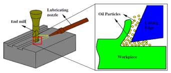
Minimum Quantity Lubrication, also known as ‘Near Dry machining’ is a process where very small amount of fine particles of good quality lubricant is sprayed over at the point of contact between the tool and the workpiece [16]. The purpose of using such a lubrication systems adds to many benefits over the conventional processes. In the MQL processes the applied lubricant not only serves the purpose of lubrication but also acts as a coolant to a certain extent. One of the many benefits of using MQL over flood coolants is that it eliminates the post processing equipment involved which include filtering the coolants using bulky machines for pumping, treating and usage of other recycling devices. Thus with its very small setup MQL can save a lot of space as far as the workplace is considered. Also as it involves very less amount of lubricant, the user doesn’t have to worry about the treating the fluids and disposing it. It can merely be wiped off by a table cloth [15]. Whereas in the flood coolant, it is a tedious process, first we have to treat the fluid and recycle it such that when it is disposed off, doesn’t cause any harm to the environment. Most of the times that is very difficult to do so when you are dealing large amounts of fluids. Thus MQL can be considered as a process which is environmental friendly. This aspect can further be improved if the lubrication used in MQL is 100% biodegradable.
As we can see MQL has benefits which saves cost, space and environment, let us discuss the machinability results. One of the main reasons we use flood coolant is that the constant supply of coolant which is relatively at lower temperature, dissipates the heat from the tool and the workpiece which in turn prevents from any immediate tool wear or poor machining finish. This is why it is very popular and hence ‘conventional’. But MQL also serves the same purpose. As mentioned earlier, the lubrication provided acts both as a coolant and a lubricant [14]. This means that at workpiece-tool interaction, the heat generated is dissipated through the lubricant into the chips formed and as the chips are separated away from the workpiece, some heat in a way is also separated from the workpiece. Which means less heat in the workpiece-tool interaction and less tool wear and better machined finish. The reason this process is successful is because MQL sprays very fine or small size of droplets onto the workpiece, which means the lubricant is involved with every tiny surface and the chips formed from the workpiece. The interaction of the lubricant with the tool and the workpiece is such that the heat generated at this interface vaporizes the little lubrication sprayed on, this makes the chips cleaner and no extra effort goes on to process or dispose off the lubricant from these chips as it has already been consumed. Thus this interaction at such a small scale makes MQL more efficient. It is also important to maintain the correct amount of lubrication that is sprayed onto the workpiece. The application should not be too much nor should it be too less for it to obtain optimum results as discussed by Amrita et al [17]. The performance of MQL process all depends on the contents of the lubricant that is been used. Also from their work it can be seen that inclusions nanoparticles can improve the performance of the process even further.
 |
| Figure 1 Schematic diagram of MQL machining |
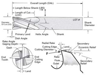 |
| Figure 2 Four flute end mill cutter tool geometry [21] |
Tool life refers to the amount of time a particular tool can be used for until it no longer usable to get the desired machining results. It is often quantified as number of minutes the tool was used for cutting. The term ‘usable’ can be subjective and depends on the machining process being carried out. For instance the tool life for a roughing operation for a particular tool can be different from that of the finishing operation [18]. Tool life is an important factor for the machinist to take into consideration in order to get optimum machining results and also to avoid unnecessary use of frequent use of new tools. For the simple reason that using more and more tools can increase the production cost. It is obviously not use possible to use the same tool forever as there is eventually going to be some wear as it is being used over the period of time. Thus it is important to critically analyze the factors that influence the tool life, so as to improve the duration for which the tool can be safely used to get better machining results [19]. Tool life is often associated the tool wear, as in the life of a tool ends upon certain degree of tool wear observed.
From the Figure 2 we can check out the different tool geometries and the nomenclature associated with it. Of all the surfaces the flank face, rake face and nose of the tool are very important. Any damage to these surfaces can lead to drastic changes in the surface finish of the machined workpiece. Thus the aim is to avoid the wear on these surfaces. From the image it is not very clear what the flank faces are. It can be clearly observed that the primary cutting edge is along the length of the tool. By definition the cutting edge is theoretical line of intersection between the rake and the flank surfaces [20]. Thus the flank face is were primary land is marked. Also the ‘Land’ marked in the top view image is the secondary cutting edge. This edge is also important as this edge is directly in contact with the machined surface. Any wear on this surface could possibly lead to poor surface finish. The relief angles provided on the tools are so as to gap between the tool and the workpiece to avoid tool breakage. However if the relief angle is too high it can cause the tool to chip or even break [20]. The clearance angles are for the chips to easily separate out from the tool-workpiece interface. If the clearance angles are not appropriate enough then, the chips forming at high temperature may get adhered to the rake surface and thus affecting the purpose of rake and clearance and thus resulting in poor surface finish.
As mentioned earlier the three major surfaces where tool wear occurs are the flank, rake and tool nose surface. Any form of wear along these surface leads to poor surface finish of the workpiece. Tool wear is often measure in terms of flank wear. As the name suggests, the wear along the flank face is considered as the flank wear. The wear along depth of the ‘land’ of the primary cutting edge is the extent of flank wear. This wear can be in any form, that is, it could be chipping, adhesion, plastic deformation, abrasion, or attrition.
In the study conducted by A. Jawaid et al [22], it was found that the tool failure occurs due to maximum wear on the flank face and also due to excessive chipping on the flank face. They used uncoated carbide tools with constant cutting parameters and the experiments were conducted with dry machining process. They found that dominant tool wear was diffusion and attrition, also they noticed that the dominant tool wear was abrasion wear on the flank face and the nose of the tool. They concluded by saying that the maximum flank wear was the factor that decided the tool life.
In the study conducted by A. Jawaid et al [22], they used two different types of coated tool and analyzed the tool wear mechanisms on different surfaces. They used flood coolant to carry out all of their experiments. Chipping and flaking were found to be the dominating wear mechanisms for most of the experiments and were found on the cutting edge and the rake face of the tool. Other tool wear mechanism observed were plastic deformation, delamination, adhesion and thermal cracks were also observed. It was concluded that CVD tools performed better than PVD tools.
In the study conducted by S. Odelros et al [23], they carried out turning experiments of Ti alloy with WC uncoated tools with wet or flood machining conditions. The aim of this study to find the reasons for tool failure through crater wear mechanism only and how does it lead to tool failure. This study included both experimental as well as theoretical data to support their findings. They found out that crater wear is the primary reason for tool failure. The crater is usually very close to the cutting edge and when the crater reaches a critical size, any further machining cause the tool failure i.e the cutting edge usually chips off, until this point the flank wear is minimal.
In the study conducted by Rosemar B. da Silva et al [24], they carried out milling operation at high speed machining with varying pressures of application of the coolant. The tools they used were PCD (Polycrystalline Diamond) tools which are known for being very high hardness. The aim of their study was to figure out tool performance under the aforementioned conditions. They found that best conditions were when the coolant was supplied at high pressure and machining speed was relatively low. As far as tool wear is concerned, tool wear with highest damage was observed on the flank face and to a certain extent on the nose. Whereas the dominating tool wear mechanism was adhesion and attrition
In the study conducted by Niharika Swain et al [25], they carried out experiments with micro-milling process of nickel super alloys. They basically used two different types of tools, that is uncoated and TiAlN coated tools with optimum machining parameters already defined from the previous studies. The aim of this work was to find which tools performed better in terms of tool life and workpiece surface integrity. A constant flow rate of coolant was supplied to the workpiece-tool interface during the machining process. It was observed that the TiAlN coated tools performed better than the uncoated ones, as coated tools have extra layer of resistance to tool wear. It was also observed that that as the cutting speed was increased flank wear was observed to be prevailing for both the tool types. Even the burrs gradually increased as the cutting distance was increased. But yet the overall results were much better for TiAlN coated micro tools.
In the study conducted by C. Ramirez et al [26], they carried out experiments with tungsten carbide (WC) 10% Co carbide tools to machine Ti alloys using dry machining process. The aim of this study was to understand the diffusion wear mechanism of the tools. It is proposed that a layer of TiC is formed at the tool-workpiece interface in the early stage of machining. At the tool WC gradient kept on decreasing and rich in Co, thus no diffusion into the Ti alloy. Whereas at the Ti ally the Co and C diffused further than W, thus depleting the tool. Nevertheless TiC layer still holds to be limiting steps for significant tool wear.
In the study conducted by Irfan Ucun et al [27], they carried out experiments with micro milling of Inconel 718 super alloy with uncoated WC carbide and different types of coated carbide tools. Also the machining conditions used were dry and MQL processes. Out of all the coated tools used TiAlN carbide tools proved to have better results. The BUE was relatively lesser than other tools and also the tool edge radius didn’t wear off easily. It was strange to notice that unlike conventional machining the wear at lower cutting speeds was much higher. Also the results from MQL experiments were far better than the dry ones as it significantly improved the tool life.
In the study conducted by Rukmini Srikant Revuru1 et al [28], they reviewed recent literature about application of cutting fluid while machining Ti alloys. Essentially in this review they are focusing on advantages n disadvantages of using different machining conditions such as dry, flood, MQL and cryogenic cooling. It also takes into consideration the coated carbide and the uncoated carbide ones. It was concluded that coated carbides give better performance results and so does MQL process.
In the study conducted by Kaining Shi et al [29], they carried out dry machining on magnesium alloy. The process used was high speed milling. It was observed that the dominant tool wear found were adhesion, abrasion and diffusion. As the wear in the tool gradually increased the surface roughness also gradually increased. It was observed that the wear higher cutting speed was much lesser that of lower cutting speeds. It was also observed that after a while of machining there was BUE on the flank face and a mass of workpiece material was piled up below the cutting edge. The severity of tool wear resulted in different chip morphologies formed.
Experimental setup
Since majority of the parts made from Titanium have to be machined by milling operation, this study focuses on Milling of Titanium. Because of all the mentioned benefits about MQL, the presented work involves experiments with MQL process to study how it affects the tool wear with different machining parameters. For the experimental trials, the machine used was a mini CNC milling machine. The machining parameters were chosen from the previous study. Thus all experiments were carried out at the high speed machining and so the spindle speed was chosen to be the highest speed that the machine could operate on which was 50 m/min. The other parameters such as the feed rate and depth of cut were varied as per the previous study. In the Table 1 we can see the different variations of feed rate and depth of cut used.
| Table 1 Tool geometry and machining parameters | |
| Tool | |
| Tool diameter (mm) | 9.53 |
| Helix angle (°) | ??? |
| Corner radius (°) | ??? |
| Cutting parameters | |
| Feed (mm/rev) | 0.1, 0.3, 0.5 |
| Radial depth of cut (mm) | 0.2, 0.3, 0.4, 0.5 |
| Cutting speed (m/min) | 50 |
The tool inserts used for the experiments were of two types namely uncoated Tungsten carbide and TiAlN (Titanium Aluminum Nitrate) coated Tungsten carbide tools. All the tools are 4 fluted and 1/8in x 1/8in.
The workpiece used was Titanium alloy (Ti-6Al-4V) as it is the most common Ti alloy used due to its wide variety of applications. The mechanical properties of the metal alloy is shown in Table 2. And chemical composition of Ti alloy is as shown in Table 3.
| Table 2 Mechanical properties of the Ti metal alloy | |
| Parameter | Value |
| Density (kg/m3) | 4430 |
| Melting point (°C) | 1668 |
| Thermal conductivity (W/m/°C) | 7.3 |
| Ultimate strength (MPa) | 950 |
| Specific heat (J/(kg/°C)) | 526 |
| Yield strength (MPa) | 820 |
| Young’s modulus (GPa) | 113.8 |
| Poisson’s ratio | 0.342 |
| Table.3 Chemical composition of Ti alloy | |
| Element | Weight% |
| Ti | Base |
| Al | 5.5–6.75 |
| V | 3.5–4.5 |
| Fe | <0.25 |
| C | <0.08 |
| N | <0.05 |
| H | <0.01 |
| O | <0.2 |
Along with varying machining parameters, experiments were also conducted with different machining conditions namely: dry machining, flood machining and Minimum Quantity Lubrication (MQL). Out of the three, dry machining and flood machining are known as the conventional type of machining, whereas MQL can be considered as unconventional as it is relatively new.
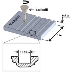
The workpiece used was a rectangular bar of dimension 3in x 3in x 0.5in and the experimental trials were carried on this rectangular bar. For each trial a new fresh tool would be chosen, a particular set of machining parameters would be chosen and a slot from one end to other would be machined. This machined slot is preserved and the tool used is also preserved and marked with the parameters used to perform the experiment. Then again a new fresh tool is used to repeat the same thing but this time with a different machining parameter.
 |
| Figure 3 Schematic illustration of milling process |
On the milling machine a dynamometer is setup which can record the cutting forces acting at the tool-workpiece interaction. It gives out the information about maximum forces and average forces acting in all three directions that is X, Y, Z axis. There is also a setup of infrared camera which can record the tool tip temperature during the machining process. These information can be very useful, specially to analyze tool wear mechanisms such as chipping, adhesion and thermal cracks.
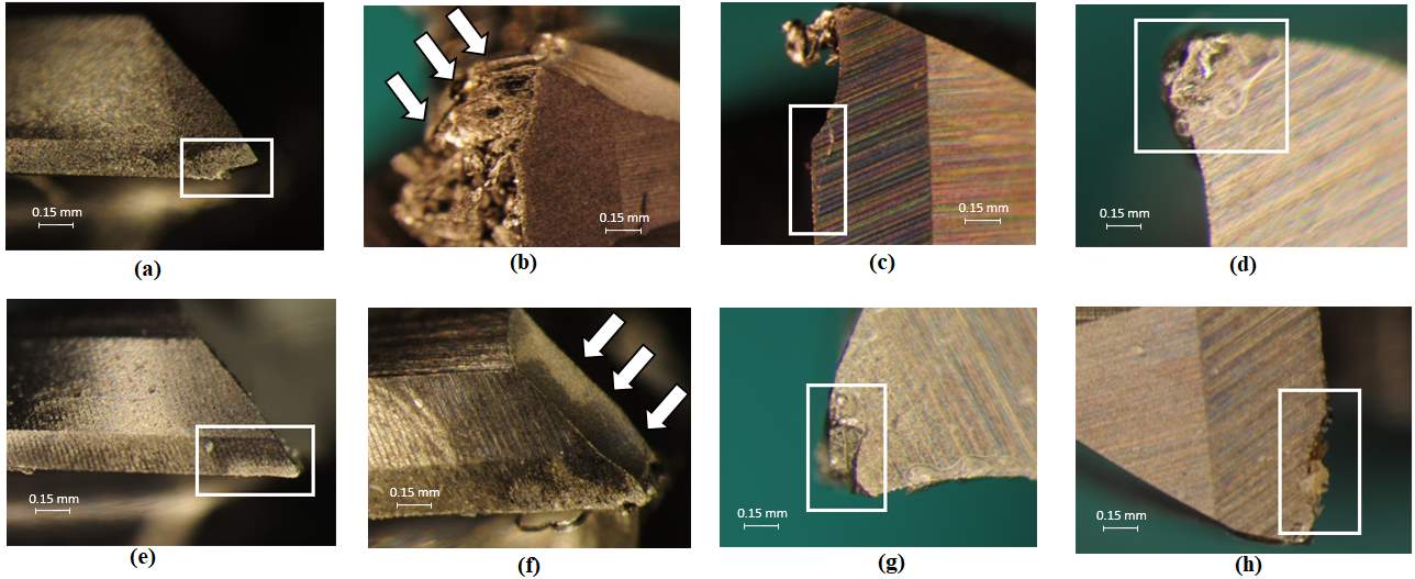 |
| Figure 4 Tool wear observed (a) Chipping (b) Adhesion (c) Crack (d) Plastic deformation (e) Abrasion (f) Plastic failure (g) Notch wear (h) Crater wear |
The preserved tools and the workpiece are then analyzed later on under light micro-scope and SEM (Scanning Electron Microscope). The different tool wear mechanisms formed at different machining conditions are recorded. In some cases XEDS analyses is also performed in order to retrieve more information about which elements are displaced where. This information is helpful as you come to know if there is really any adhesion from the workpiece or any built up edge, and through elemental mapping deduce further results.
Results and discussion
Tool wear mechanisms:
In the experiment trial conducted, there were many tool wear mechanism observed. The figure 4 shows all the different types of tool wear mechanism that were observed during the experiments
Abrasion:
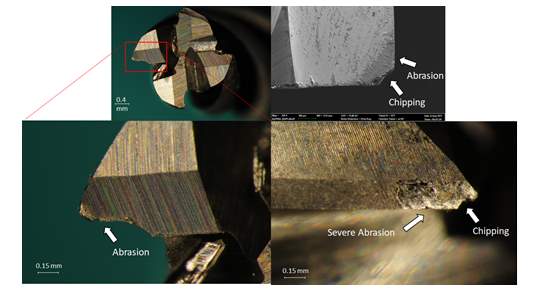
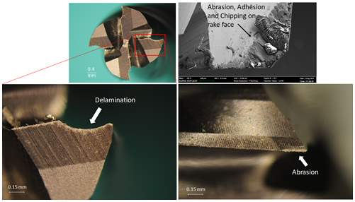
Abrasion is the most common wear observed in all types of machining conditions and for both uncoated and coated tools. It is mainly observed on the flank face of the primary cutting edge of the tool and thus is one of the primary reasons for majority of the flank wear. Abrasion wear occurs due to hard particles interacting at the tool-workpiece interface. For instance, when some part of the chips when gets locked onto the workpiece-tool interface and the machining operation is still continued these particles gets dragged on, this causes abrasion wear on the tool surface. This justification is valid as we see abrasion wear for all the machining conditions, and as it prevails for all the condition, it cannot be eliminated and can only be minimized. Machining at high speed can the reason abrasion wear prevails for all the conditions Jie Gua et al [30]. Abrasion wear causes the carbide elements in the tool to protrude out of the flank face and hence disturbing the geometry of flank face. Abrasion wear is not desired as it can not only wear off the tool quickly but also cause poor surface finish on the workpiece.
Chipping:
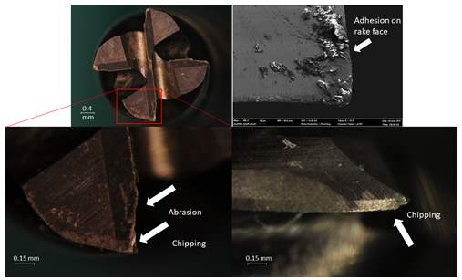
Chipping is another common type of tool wear mechanism found in most of the machining condition, but not as much as abrasion wear. Chipping is caused by higher forces acting on the tool. It can be easily identified as when chipping occurs it makes the rake angle more negative and when it occurs it totally changes the geometry of the tool Jie Gua et al [30]. Chipping is also caused due to high stresses and high temperatures at the cutting edge in addition to the brittleness of the tool. These are the reasons which can cause chipping to occur quickly. Chipping is more likely to be found on the cutting edges, then on the rake face and sometimes in the tool nose as well. If the chipped cutting edge is further used, it can lead to flaking. This condition of the tool is not desired as it can cause result in very poor surface finish A. Jawaid et al [31]. Machining parameters can affect the chipping that takes place. A higher depth of cut or even a high feed rate can lead to chipping. Thus chipping can be avoided if the machinist uses proper machining parameters.
In the figure it can be seen the chipping is at the flank face of the tool but it is also towards the nose of the tool.
Adhesion:
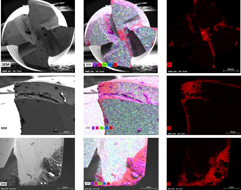 |
| Figure 5 XEDS analysis of MQL machining for uncoated carbide tool |
Adhesion is a tool wear in which a part of the workpiece gets attached to the tool. This can change the geometry of the tool and thus if any further machining is done, then an undesired surface roughness is seen as the result. Adhesion can be caused of several reason, one of them being that during the machining process, due to friction a significant amount of heat is generated. Sometimes it can so happen due to this high temperature small particles of the workpiece gets fused to the tool. In such a case, it is quite possible to form a built up edge (BUE). It is usually seen at the nose of the tool and sometimes also at the rake face. This BUE can be advantageous to a certain extent and beyond which can will result in poor finish of workpiece. Some of the adhesion can be so bad that the tool had to be discarded immediately, just like in the figure. Adhesion can be high in dry machining process as there very high temperatures generated and there is no mode of cooling it down. Also if extreme machining parameters are chosen, that high depth of cut or high feed rates or even both.
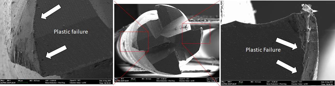
Plastic failure
Plastic failure is when a part of the flute or an edge of the tool is catastrophically chipped off or the entire tool catastrophically fails midway machining. Usually such a failure occurs when the machining parameters chosen are unusually higher than normal. In the figure we can notice that an edge is chipped off from the tool. This is obviously not desired and the tool has to be replaced immediately after the failure occurs.
 |
|
| Figure 6 SEM image of tool displaying plastic failure | |
Plastic deformation
In plastic deformation, the tool undergoes softening and it is deformed plastically. This could be due to high temperatures generated and a particular grade of tool is not suitable to withstand it. In the figure it can be observed that the tool nose has lost its original geometry. Another reason that could possibly result in plastic deformation is that if when higher concentration of compressive stresses are acting over a very small contact area, this wear could take place A. Jawaid et al [31].
Notch wear
Notch wear usually takes place at the nose of the tool, and the wear is much sharper along the secondary cutting edge and also along the flank of the tool. This can be seen in the figure
Delamination:
It is that type of tool wear mechanism which limited to coated tools only. In this kind of tool wear (as the name suggests), the coating of the tool is removed or delaminated [31]. As it us just the top layer of the tool which is being depleted, theoretically it should be usable again and still get better surface finish. In the figure we can observe delamination on secondary cutting edge.’
Crack
Cracks or sometimes also referred as thermal cracks were not seen much in these experiments, that is, just a couple of occurrences. This phenomenon is seen in flood coolant machining. As we know, there is a significant amount of heat generated during machining, and if a constant flow of coolant is
 |
| Figure 7 Tool wear on flank face, rake face, and secondary cutting edge for dry machining |
 |
| Figure 8 Tool wear on flank face, rake face, and secondary cutting edge for flood machining
|
 |
| Figure 9 Tool wear on flank face, rake face, and secondary cutting edge for MQL machining |
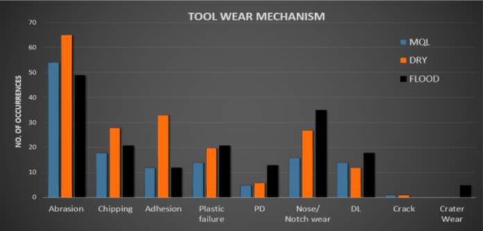 |
| Figure 10 Tool wear mechanism occurrences for all machining conditions |
supplied to this process, there is going to be temperature fluctuations. This temperature fluctuation is known as thermal shock. Hence it is due to these thermal shocks that there are thermal cracks formed [31]. In the figure we can observe an occurrence of crack on the secondary cutting edge. Crack propagation can potentially lead to plastic failure of the tools.
Crater wear
Crater wear is usually associated to wear happening due to chemical process. It is observed on the flank face of the tool but is very close to the primary cutting edge. The wear looks similar to chipping but it’s only deeper when it comes to crater. A crater when reaches a critical size, if used any further results into a fracture and then eventually in tool failure [23]. The occurrences of crater wear were very few as the machining time for the experimental trials is very low. In the figure we can see the only occurrence of crater wear on the primary cutting edge.
Comparing all the machining condition results
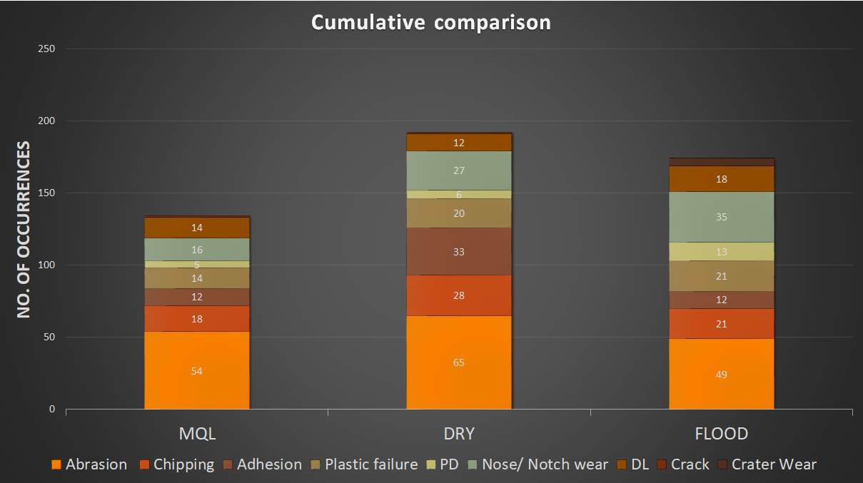
A part of this study is to analyze the tool wear occurring in each machining conditions, that is dry, flood and MQL conditions. The Figure [10] shows the number of occurrences of each tool wear observed with different machining conditions. From the graph is quite clear that abrasion wear is the most frequent tool wear observed irrespective of the machining condition. For abrasion wear dry machining was recorded to have the highest no. of occurrences followed by flood machining and MQL respectively. This confirms our discussion on abrasion wear that it is the most common and frequently occurring tool wear and changing the machining conditions doesn’t improve the results. Thus we can say that abrasion is the dominant tool wear amongst all the machining conditions.
Second most dominating tool wear recorded was chipping and adhesion wear. From the Figure [10] we can observe that again dry machining has the highest number of occurrences for both the tool wears. This confirms our previous discussion that since dry machining causes a very high temperature at the tool-workpiece interface and more stresses are acting as there no lubrication provided to reduce the cutting forces, it is bound to have poorer results than flood and MQL machining. Flood machining has the second highest number of occurrences for chipping and adhesion wear followed by MQL machining which had the least number of chipping and abrasion recorded.
Following chipping and adhesion, the tool wear mechanisms dominating were plastic failure and notch wear. From the Figure [10] we can observe that flood machining has higher occurrences than dry machining followed by MQL which again had the least number of occurrences recorded, in fact for MQL trial the number of occurrences for notch wear were almost half that of the flood machining. The tool wear plastic failure and notch were mostly recorded with extreme machining parameters, that is, depth of cut = 0.5 mm and feed rate = 0.5 mm/rev. If we wish to avoid these tool wears, we can choose machining parameters less than the above mentioned ones. There have been many studies which have tried to optimize the machining parameters to have minimum tool wear [13].
Next dominating tool wear is delamination (DL in the Figure 10-13) of coated tools. From the Figure [10] we can notice that flood machining had the highest number of occurrences followed by MQL. Deviating from the trend of having the highest number of occurrences of tool wear for dry machining, for this particular delamination wear dry condition had the least number of occurrences. This goes on to prove that coated tools give poorer results when any kind of lubrication is involved. Thus when operating on dry machining condition, it is advised to work with coated tools.
Moving on to lesser dominating tool wear mechanisms, next is plastic deformation (PD in the Fig 10-13). Here we can observe that although there are very few occurrences for all the conditions, flood machining has the highest number recorded followed by dry machining and then MQL having the least occurrences with less than half occurrences than that of flood machining. And finally the tool wear, thermal crack and crater wear had the least number of occurrences. Surprisingly there were no cracks in flood machining trials and dry and MQL conditions barely had a couple of occurrences overall, it can be considered as negligible. Whereas for crater wear, dry and MQL conditions had no occurrences. On the other hand flood machining did have some occurrences of crater wear.
Comparing tool wear according to tool geometry
The Figure [11-13] show tool wear distribution on a flank face, rake face and secondary cutting edges respectively. In the Figure [11] we see mostly abrasion wear and plastic failure on the flank face. We can observe that MQL condition has lesser wear on the flank face as compared to other two conditions.
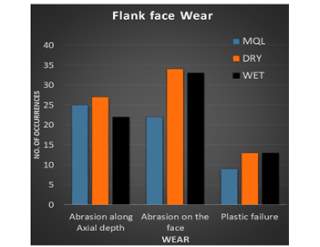 |
| Fig. 11 Wear on the flank face |
The Figure [12] shows wear on the rake face with abrasion being the most dominating tool wear, followed by chipping, plastic failure, delamination and adhesion respectively in that order. Apart from abrasion and chipping, MQL condition was recorded to have lesser tool wear than other two conditions.
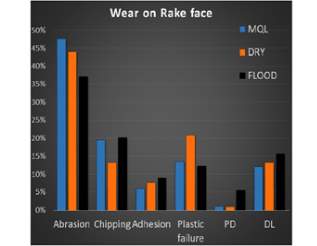 |
| Fig. 12 Wear on the rake face |
In the Figure [13], we can observe different tool wear mechanisms on the secondary cutting edge of the tool. The most dominating tool wear observed here is adhesion and that too just dry machining showing more than twice occurrences as compared to MQL which had the least count. Second most dominating tool wear observed was chipping and it was observed mostly along the clearance face of the edge. Notch wear and crater wear had very few occurrences amongst which MQL condition showing fewer occurrences than the conventional machining conditions.
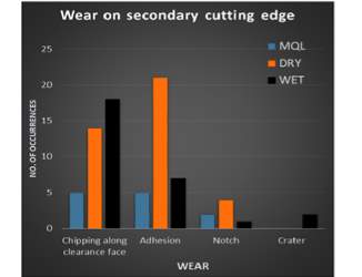 |
| Fig.13 Wear on secondary cutting edge |
conclusions
The conclusions drawn from milling Ti alloy Ti-6Al-4V for dry, flood coolant and MQL machining conditions using uncoated carbide and TiAlN carbide tools to determine the tool wear mechanisms are as follows:
 |
| Figure 4 Cumulative comparison of tool wear with different machining conditions |
- In dry, MQL and flood coolant machining abrasion wear is the most dominating tool wear observed. Although the occurrence of abrasion was fewer in MQL and flood machining than dry machining.
- Abrasion was also found to be dominating on the flank face and the rake face, which are the two important faces on which wear shouldn’t take place in order to achieve better machining results.
- The second most dominating tool wear observed was chipping and adhesion with dry machining have the highest occurrences and MQL having the least. Primary reason for these wears wear was that the trials were carried out at high depth of cut and feed rates.
- There were some cases of plastic failure of tool flutes and edges, with again dry and flood machining having more occurrences of tool failure than MQL.
- Delamination was more significant in flood coolant and MQL machining compared to dry machining, indicating the effectiveness of coated tools in dry machining compared to wet and MQL machining.
- Overall, MQL provided the least occurrences of tool wear, indicating suitability of MQL in productive machining titanium alloys over the conventional machining conditions.
The final conclusion is made by simply observing Figure 14 which compares the cumulative number of wear occurrences for different machining conditions.
Acknowledgments
In drafting this paper, I have benefited a lot from comments and criticisms of others. First, I would like to express my sincere gratitude to CAMI (Center of Advanced Microscopy and Imaging) department, Miami University for usage of optical microscope and SEM usage. And I am also grateful to Department of Mechanical and Manufacturing Engineering, Miami University, which kindly gave me permission to have access to the equipment regarding my case study.
References
[1] Liu, Xuanyong, Paul K. Chu, and Chuanxian Ding. “Surface modification of titanium, titanium alloys, and related materials for biomedical applications.” Materials Science and Engineering: R: Reports 47.3 (2004): 49-121.
[2] J. Chae, S.S. Park, T. Freiheit, Investigation of micro cutting operations, Int. J. Mach. Tools. Manuf. 46(2006) 313-332.
[3]Thanongsak Thepsonthi & Tuğrul Özel, An integrated toolpath and process parameter optimization for high-performance micro-milling process of Ti–6Al–4V titanium alloy, Int J Adv Manuf Technol (2014) 75:57–75.
[4] Aurich JC, Dornfeld D, Arrazola PJ, Franke V, Leitz L,Min S (2009)Burrs-analysis, control and removal. CIRP Ann Manuf Technol 58(2):519–542.
[5]A.Ginting a, M.Nouari, Surface integrity of dry machined titanium alloys, International Journal of Machine Tools & Manufacture 49 (2009) 325–332
[6]Balkrishna Rao, Chinmaya R. Dandekar, Yung C. Shin. An experimental and numerical study on the face milling of Ti–6Al–4V alloy: Tool performance and surface integrity. Journal of Materials Processing Technology 211 (2011) 294–304.
[7]Ezugwu, E.O., Bonney, J., Yamane, Y., 2003, An Overview of the Machinability of Aeroengine Alloys, Journal of Materials Processing Technology,134:233–253.
[8]Kline, W. A., R. E. DeVor, and I. A. Shareef. “The prediction of surface accuracy in end milling.” Journal of engineering for industry 104.3 (1982): 272-278.
[9]Aramcharoen, A., et al. “Evaluation and selection of hard coatings for micro milling of hardened tool steel.” International Journal of Machine Tools and Manufacture 48.14 (2008): 1578-1584.
[10]Masuzawa, Takahisa. “State of the art of micromachining.” CIRP Annals-Manufacturing Technology 49.2 (2000): 473-488.
[11]Aramcharoen, A., and P. T. Mativenga. “Size effect and tool geometry in micromilling of tool steel.” Precision Engineering 33.4 (2009): 402-407.
[12]Singh P, Pungotra H, Kalsi NS (2016) On the complexities in machining titanium alloys in CAD/CAM. In: Robotics and factories of the future. Springer, New Delhi, pp 499–507.
[13]Baskar, N., et al. “Optimization of machining parameters for milling operations using non-conventional methods.” The International Journal of Advanced Manufacturing Technology 25.11-12 (2005): 1078-1088.
[14]Sun, J., et al. “Effects of coolant supply methods and cutting conditions on tool life in end milling titanium alloy.” Machining Science and Technology 10.3 (2006): 355-370.
[15]Dhar, N. R., M. Kamruzzaman, and Mahiuddin Ahmed. “Effect of minimum quantity lubrication (MQL) on tool wear and surface roughness in turning AISI-4340 steel.” Journal of materials processing technology 172.2 (2006): 299-304.
[16]Wakabayashi T, Kuhara J, Atsuta T, Tsukuda A, Sembongi N, Shibata J, Suda S (2015) Near-dry machining of titanium alloy with MQL and hybrid mist supply. Key Engg Mat 656–657:341–346.
[17]Amrita, M., R. R. Srikant, and A. V. Sitaramaraju. “Evaluation of cutting fluid with nanoinclusions.” Journal of Nanotechnology in Engineering and Medicine 4.3 (2013): 031007.
[18]Che-Haron, C. H. “Tool life and surface integrity in turning titanium alloy.” Journal of Materials Processing Technology 118.1 (2001): 231-237.
[19]Da Silva, Rosemar B., et al. “Surface integrity and tool life when turning of Ti-6Al-4V with coolant applied by different methods.” The International Journal of Advanced Manufacturing Technology 93.5-8 (2017): 1893-1902.
[20]Stephenson, David A., and John S. Agapiou. Metal cutting theory and practice. CRC press, 2016.
[21]End mill cutter nomenclature, Destiny Tool, http://www.destinytool.com/technical.html.
[22]Jawaid, A., S. Koksal, and Safian Sharif. “Cutting performance and wear characteristics of PVD coated and uncoated carbide tools in face milling Inconel 718 aerospace alloy.” Journal of Materials Processing Technology 116.1 (2001): 2-9.
[23]Odelros, S., et al. “Experimental and theoretical study of the microscopic crater wear mechanism in titanium machining.” Wear 376 (2017): 115-124.
[24]da Silva, Rosemar B., et al. “Tool life and wear mechanisms in high speed machining of Ti–6Al–4V alloy with PCD tools under various coolant pressures.” Journal of Materials Processing Technology 213.8 (2013): 1459-1464.
[25]Swain, Niharika, et al. “An experimental investigation on the machining characteristics of Nimonic 75 using uncoated and TiAlN coated tungsten carbide micro-end mills.” CIRP Journal of Manufacturing Science and Technology 16 (2017): 34-42.
[26]Ramirez, C., et al. “Understanding the diffusion wear mechanisms of WC-10% Co carbide tools during dry machining of titanium alloys.” Wear 390 (2017): 61-70.APA.
[27]Ucun, Irfan, Kubilay Aslantas, and Fevzi Bedir. “An experimental investigation of the effect of coating material on tool wear in micro milling of Inconel 718 super alloy.” Wear 300.1 (2013): 8-19.
[28]Revuru, Rukmini Srikant, et al. “Application of cutting fluids in machining of titanium alloys—a review.” The International Journal of Advanced Manufacturing Technology 91.5-8 (2017): 2477-2498.
[29]Shi, Kaining, et al. “Tool wear behaviors and its effect on machinability in dry high-speed milling of magnesium alloy.” The International Journal of Advanced Manufacturing Technology (2016): 1-9.
[30]Gu, Jie, et al. “Tool life and wear mechanism of uncoated and coated milling inserts.” Wear 225 (1999): 273-284.
[31]Jawaid, A., Safian Sharif, and S. Koksal. “Evaluation of wear mechanisms of coated carbide tools when face milling titanium alloy.” Journal of Materials Processing Technology 99.1 (2000): 266-274.
Cite This Work
To export a reference to this article please select a referencing stye below:
Related Services
View all


Related Content
All TagsContent relating to: "Mechanics"
Mechanics is the area that focuses on motion, and how different forces can produce motion. When an object has forced applied to it, the original position of the object will change.
Related Articles

DMCA / Removal Request
If you are the original writer of this dissertation and no longer wish to have your work published on the UKDiss.com website then please: