Strengthening of Poorly Graded Timber with Laminated Bamboo
Info: 16026 words (64 pages) Dissertation
Published: 26th Nov 2021
Tagged: ConstructionEngineering
Abstract
This thesis investigates the strengthening of poorly graded timber, namely Sitka spruce, with a single layer of bleached, laminated bamboo. This study aimed to provide a materially efficient, natural method for the strengthening of poorly graded timber.
Through a literature review, it was found that laminated bamboo presents several superior mechanical properties when compared to Sitka spruce. The significantly increased tensile yield strength suggested that the material presents a viable option for the tensile strengthening of Sitka. The environmental effects of bamboo growth and processing were also discussed. Bamboo plantations were found to have several beneficial impacts on the surrounding environment, whilst life cycle analyses on the production process suggest laminated bamboo could carbon neutral material, even when transported to Europe.
The mechanical behaviour of 15 hybrid samples consisting of varying proportions of laminated bamboo and Sitka spruce were tested to failure in bending. The results were then compared to previous studies concerning the strengthening of timber with two or more layers of laminated bamboo.
The results from this study suggested that an increased depth of laminated bamboo provided an increase in the modulus of rupture. Conversely there appears to be no clear relationship between bamboo depth and the modulus of elasticity. The hybrid samples all exhibited a much larger modulus of rupture than Sitka spruce, however the 10mm laminated bamboo hybrids affected a much larger increase per unit volume of bamboo than the other hybrids. The hybrids exhibited an increase in modulus of elasticity when compared to published data on Sitka spruce, but no improvement on the Sitka spruce samples tested in this study.
Comparing the results in this study to those of Archer (2016), for Sitka spruce reinforced with a further layer of laminated bamboo, showed the samples in this study to have a noticeably lower stiffness. Conversely the further reinforcement used by Archer appeared to have no effect on the ultimate strength of the hybrid.
The findings of this study provide a preliminary indication of the benefits of strengthening poorly graded timber with laminated bamboo. The significant improvement in strength that is shown by these hybrid beams suggests this method does provide a viable and environmentally friendly alternative to conventional strengthening techniques. The lack of a significant improvement in stiffness may however limit its range of applications.
Contents
Click to expand Contents
1.0 Introduction
1.1 Aims
1.2 Sustainable materials in construction
1.3 Bamboo
2.0 Literature Review
2.1 Environmental impact of bamboo in construction
2.2 Engineered bamboo
2.3 Laminated bamboo-timber hybrid sections
2.4 Composite beam behaviour
2.5 Summary
3.0 Methodology
3.1 Materials
3.2 Section specification
3.3 Specimen preparation
3.4 Test procedure
4.0 Prediction of results
4.1 Plane stress analysis
4.2 Adhesive shear strength
4.0 Results
4.1 Comparison of hybrid sections
4.1.1 Modulus of rupture
4.1.2 ;Modulus of elasticity
4.1.3 Load-displacement plot
4.1.4 Density relationship
4.1.5 Discussion
4.2 Comparison of hybrid sections to Sitka spruce
4.2.1 Modulus of rupture
4.2.2 Modulus of elasticity
4.2.3 Load-displacement plot
4.2.4 Discussion
4.3 Comparison to doubly reinforced hybrids
4.3.1 Modulus of rupture
4.3.2 Modulus of elasticity
4.3.3 Discussion
4.4 Strain analysis
4.4.1 Maximum tensile fibre strain
4.4.2 Strain profile
4.4.3 Discussion
4.5 Failure modes
5.0 Conclusion
6.0 Recommendations for further research
Bibliography
List of figures
Figure 1 – Bamboo culm cross-section (Bamboo Botanicals, 2017)
Figure 2 – Cross section of a bamboo culm (Liese, 1998)
Figure 3 – Yield and bending strength of 3 species, Hybrid Poplar, Spruce and Moso Bamboo (Amino, 2003)
Figure 4 – Carbon footprint (kgCO2/kg) for carbonized 3-layer laminated bamboo board (van der Lugt, et al., 2012)
Figure 5 – Bamboo scrimber, bleached laminated bamboo and caramelised laminated bamboo (Plyboo, 2017)
Figure 6 – Lay-ups of hybrid beams (Chen, et al., 2016)
Figure 7 – Lamination process
Figure 8 – Four point bending set up to BS 373
Figure 9 – Four point bending test set up on the 100kN universal testing machine
Figure 10 – Predicted stress distribution in hybrid samples
Figure 11 – Localised crushing beneath asymmetric loading
Figure 12 – Load-displacement plot of maximum, minimum and median MOR hybrid samples
Figure 13 – Relationship between density and modulus of rupture
Figure 14 – Relationship between density and modulus of elasticity
Figure 15 – Load displacement plot of median MOR samples
Figure 16 – Singularly and doubly reinforced sections to be compared
Figure 17 – Hybrid strain profiles
Figure 18 – Strain profile beyond limit of proportionality
Figure 19 – Failure of timber samples
Figure 20 – Failure modes in hybrid Samples
List of tables
Table 1 – Embodied carbon compared to specific strength, [1] (Hammond & Jones, 2011)
Table 2 – 3 Hybrid sections and solid sections of each material (Archer, 2016)
Table 3 – Timber and hybrid samples prepared
Table 4 – Material properties from Sharma et al. (2015)
Table 5 – estimated bending moment capacity and mor for hybrid samples
Table 6 – Mean MOR and MOE of hybrid samples
Table 7 – Mean MOE and MOR of Sitka spruce and hybrid samples
Table 8 – MOR for Sitka spruce samples in this study
Table 9 – Maximum MOE values in this study
Table 10 – Mean MOR and MOE for Sitka in this study and Archer (2016)
Table 11 – Mean MOR and MOE values for hybrids in this study and Archer (2016)
Table 12 – Tensile fibre strain at Fmax
Table 13 – MOE and MOR of samples failing under mechanism 2 and 3
1.0 Introduction
The purpose of this dissertation is to investigate the flexural reinforcement of poorly graded timber beams with laminated bamboo. Softwoods, such as Sitka spruce, grow in abundance in the UK and throughout Europe; however their use in construction can be severely limited by their poor flexural strength. This problem is even more apparent in temperate countries where several rapid growing softwoods are entirely redundant in construction.
Bamboo has been utilised as a construction material for thousands of years in its natural form (Kaminski, et al., 2016) with an estimated 1 billion people residing in bamboo houses, which range from simple dwellings to four-storey houses (Liese, et al., 2015). The material offers a strong, fast growing and abundant resource in temperate countries where it grows naturally. The development of processed products, such as laminated bamboo, has led to the production of standardised rectangular beams in recent years.
In this study laminates of Phyllostachys pubescens, or Moso bamboo, were adhered to samples of sawn Sitka spruce. Moso bamboo is a woody bamboo that predominantly grows in China, where it covers approximately 30,000 km2 (Dixon, et al., 2015). It is widely regarded as the most important species of bamboo in China, in terms of distribution and timber value (Li, et al., 2015; Liese, et al., 2015), contributing the majority of the 19bn yuan annual trade of bamboo in China. Sitka spruce is a softwood that grows naturally on the North-West coast of America and has been imported in to several other countries, including Britain in 1831 (Forestry Commision, 2016). In Britain it is a cheap, widely available species of timber, mainly used in construction and packaging (TRADA, 2002).
Despite sharing a very similar composition, Moso exhibits several preferable mechanical properties, with selected figures for the modulus of rupture of laminated Moso bamboo ranging between 70.1-122.4 MPa (Correal, et al., 2014; Sharma, et al., 2014; Sinha, et al., 2014) compared to 31-67 MPa (Brazier, et al., 1976; Lavers, 1983; Moore, et al., 2009a; Moore, et al., 2009b) for Sitka spruce.
Moso also has a rapid growth rate, reaching around 24m high within 40-50 days (Fu, 2001), and tends to be harvested for construction in the 5th or 6th year of growth (Janssen, 2000). Conversely Sitka has a much long crop rotation of 35-45 years (Moore, 2011). A key benefit of both of these building materials is their sequestration of carbon during their growth, however the rapid growth of Moso leads to a much higher rate of sequestration.
1.1 Aims
This study aimed to investigate the flexural properties of a hybrid beam of Sitka spruce and laminated bamboo. To achieve this, an experimental analysis of 18 samples under bending was conducted. Laminated bamboo was adhered to the tension face 15 of the samples, in three different depths, leaving 3 samples of 100% Sitka Spruce. All the samples were planed to give a total cross section of 50x50mm and tested to failure under four point bending.
To inform the study a literature review on the following topics has been carried out:
- The environmental impact of bamboo lamination and transportation, compared to that of locally sourced sawn timber;
- The lamination process, structural properties and applications of laminated bamboo;
- Previous studies on the use of laminated bamboo in bamboo-wood hybrid beams.
The literature review and data gathered from experiments will be used in completing the following objectives:
- Investigate the flexural properties of the singularly reinforced hybrid wood-laminated bamboo beams;
- Quantify the benefit of the each reinforcement regime when compared to a beam of Sitka Spruce;
- Compare the results of this study to those of Archer (2016) in order to determine the benefit of also reinforcing the compression face of the timber;
- Assess the viability of using these hybrid beams as an alternative to traditional timber beams, and discuss other possible applications of this method.
1.2 Sustainable materials in construction
As the impacts of global warming become ever more apparent, pressure has been placed upon the construction industry to replace common practices with more energy efficient options. Reduction in the use of materials such as steel and concrete, which cause large carbon dioxide emissions during their manufacture, can play a significant part in this effort. Wood based composite materials can offer a promising alternative in this, with a limited manufacturing process and appreciable sequestration of carbon dioxide during growth.
The United Nations Environment Programme estimates that between 1970 and 2004 greenhouse gas emissions due to human activities rose by around 70% (UNEP, 2009). It estimates that around 40% of this value can be attributed to the construction and use of our buildings, with around 10%-20% of this consumed in material manufacture. From these figures it is clear that even small changes within the construction industry can go a long way to reducing our global carbon emissions. When it is also considered that we have a growing human population and increasing consumption per capita (van der Lugt, et al., 2012) any opportunity to reduce the pressure on global resources must be explored.
Table 1 shows data taken from the Inventory of Carbon and Energy, Version 2.0 (Hammond & Jones, 2011) for two commonly used grades of steel and timber. An approximate value for the flexural strength to weight ratio of both materials is also provided. Both materials show a similar flexural strength to weight ratio, however timber exhibits a significantly lower value of embodied carbon. The data provided by the Inventory of Carbon and Energy also discounts the effect of Carbon sequestration during the growth of the timber and the energy that can be recovered by burning timber at the end of use. Both of these factors further reduce the net emissions of the material throughout its use.
Table 1 – Embodied carbon compared to specific strength, [1] (Hammond & Jones, 2011)
| Material | Embodied carbon (kgCO2/kg)[1] | Flexural strength-weight ratio (kNm/kg) |
| Steel – S275 | 1.37 | 34.0 |
| Timber – C16 softwood | 0.58 | 43.0 |
It reality it can be hard to achieve spans similar to those of steel with timber. A lower flexural strength and stiffness results in bulkier sections, whilst its inability to be rolled or poured makes it harder to form into optimised sections. The need for stronger, stiffer timber members has led to several studies into the reinforcement of timber beams with artificial fibres such as carbon and glass (Johns & Lacroix, 2000; Borri, et al., 2005; Valluzzi, et al., 2007; Franke, et al., 2015). Recently several studies have also looked into the use of natural fibres, such as bamboo, basalt and hemp as cheaper, more environmentally friendly alternatives (Abdul Khalil, et al., 2012; Borri, et al., 2013).
1.3 Bamboo
Bamboo is a species of giant grass, that grows naturally in tropical and sub-tropical environments (Janssen, 2000). The Global Forest Resources Assessment of 2010 estimates that bamboo plantations cover over 30 million hectares of the Earth’s surface, predominantly in Asia, South America and Africa.
Figure 1 provides a cross-section of a typical bamboo stem, or culm. Here the below ground rhizome system can be seen with roots sprouting from it. This system is vital to providing stability and nutrients to the bamboo culm above (Janssen, 2000). The culm is a hollow, segmented tube, with a series of rings, referred to as nodes, running up the full height of the culm.

Figure 1 – Bamboo culm cross-section (Bamboo Botanicals, 2017)
Within the culm wall the structural fibres are functionally graded, up the height of the culm and radially (Dixon, et al., 2015), as can be seen in Figure 2. A higher proportion of fibres are situated at the base and the outer extents of the culm, improving its flexural strength under wind loads. Bonding these fibres together is a much weaker, lignin based matrix called parenchyma (Kaminski, et al., 2016). This structure gives bamboo its heavily anisotropic behaviour. The structural fibres provide very high strength and stiffness when loaded parallel to the grain, however the parenchyma matrix is easily sheared when loaded perpendicular to the grain.
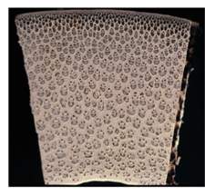
Figure 2 – Cross section of a bamboo culm (Liese, 1998)
It is estimated that there are around 1300 species of bamboo with over 1000 described uses, including food, biomass and furniture (Liese, et al., 2015). Of these species, there are around 100 ‘woody’ species which are considered to be suitable for construction. Full-culm bamboo has a long history of use as scaffolding in countries such as China, India and Thailand and can be provide good cheap housing, if designed correctly (Janssen, 2000).
Despite its abundant use, bamboo has several disadvantages. It tends to be more susceptible to decay than timber, due to a lack of natural toxins. The key threats to bamboo are attack from beetles, termites and funghi (Kaminski, et al., 2016). As briefly discussed in the introduction, full-culm bamboo is also very hard to standardise. The culm tapers in width from top to bottom, from plant to plant and varies radially within the culm wall. Forming connections between hollow tubes tends to prove difficult and the culm is very susceptible to splitting during the process. There is as of yet no formal code or standard for bamboo construction and most common practices tend to be founded on word of mouth.
These difficulties have led to the creation of several engineered bamboo products, including laminated bamboo. Much like glue laminated timber, it is formed of small laminae of bamboo which are glued and pressed to form a section of desired shape. This allows the standardisation of beams and makes connections much easier to form, whilst maintaining the inherent strength of the bamboo fibres.
2.0 Literature review
2.1 Environmental impact of bamboo in construction
2.1.1 Growth
As previously mentioned, the need for sustainable, renewable and low carbon building materials is becoming more and more prevalent. As with all plant life, bamboo sequesters carbon from the atmosphere for use in photosynthesis. The rate at which bamboo grows causes it to need larger than average levels of CO2 in order to thrive. Nath, et al. (2015) compiled numerous studies concerning the biomass Carbon storage of Bamboo and describe its potential for use in carbon farming and trading. Emissions trading, widely referred to as carbon trading, is a term described in the Kyoto protocol as an emissions trading market for permits and credits that target carbon emissions (UNFCCC, 2014). Ignoring any anomalous results, they compiled a range of biomass carbon storage in woody bamboos between 30-121 Mg ha-1. The study concluded that Moso plantations have strong potential for use in Carbon trading in countries where it grows naturally, such as China. Figure 3 plots the biomass yield of 3 species against their respective bending strength (Amino, 2003). As shown Moso bamboo not only has a higher biomass yield than the other species, but is also over twice as strong in flexure.
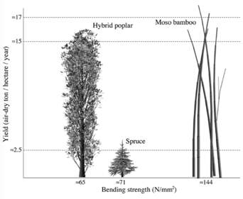
Figure 3 – Yield and bending strength of 3 species, Hybrid Poplar, Spruce and Moso Bamboo (Amino, 2003)
Similarly, a report by INBAR (2010) looked to compare the sequestration rates of the fast growing Chinese fir and Moso bamboo plantations though a literature review. The study concluded that both species had a comparable sequestration rate, however the bamboo sequestered more carbon in the first 5 years of its life. Considering that Moso bamboo is often harvested at around 5 years old, the study suggests that a properly managed plantation will sequester more carbon than a Chinese fir plantation.
Separate selected studies provide an average sequestration rate for Moso bamboo of 6.5-8.8 Mg ha-1 yr-1 (Yen & Wang 2013, Zhang et al., 2014, Isagi et al., 1997). This is comparable to the maximum sequestration rate in Sitka spruce, with estimations ranging between 5.5-9.4 Mg ha-1 yr-1, (Black, et al., 2009, Black, et al., 2007, Magnani, et al., 2007) however Magnani, et al. (2007) estimate that, averaged over the entire crop rotation Sitka has an average sequestration rate of 2.7 Mg ha-1 yr-1, significantly less than that of Moso bamboo.
Bamboo also plays a key role in maintaining land mass. Its large interlocking rhizome system provides stability to riverbanks and hillsides (Liese, et al., 2015). Plantations can also be used as a wind break for farming or local communities; and its invasive root structure can help to loosen and rehabilitate degraded soils. Plantations offer several habitats for a wide range of wildlife to thrive, providing shelter and food (Janssen, 2000).
2.1.2 Life cycle assessments
A Life Cycle Assessment (LCA) is a standardised process for determining the environmental impact of a building material, from production to eventual disuse. It is standardised in ISO 14040 and consists of 4 steps, the definition of the goal and scope, the development of life cycle inventories, impact assessment and finally interpretation of the result (Escamilla & Habert, 2014).
In a study by Votlanger, et al. (2010) LCAs are used to assess the sustainability of bamboo products in Europe. In order to do so the eco-costs system, which incorporates 3000 pollutants (Votlanger, 2010), was used as an indicator. The study found that, bamboo products have less eco-costs than tropical hardwoods, however once imported into Europe they have more eco-costs than local European softwood.
Following this study, van der Lugt, et al. (2012) used LCAs to assess the environmental impact of laminated bamboo produced by Moso International BV, using the same eco-costs method. Through this study it was found that, assuming a 5-year period of growth, bamboo plywood could be carbon neutral or better, even when transported to Europe. It is worth noting that to reach this conclusion it was assumed 90% of bamboo is burnt for energy at the end of its useful life. The energy produced by this is offset against the carbon that would be released by burning a coal-based fuel, to provide an ‘end-of-life credit’ value. This value is then deducted from the carbon footprint, as can be seen in Figure 4. It can also be seen that this figure constitutes a large proportion of the favourable CO2 usage in this study and, if overestimated, could heavily impact the positive result of the study.
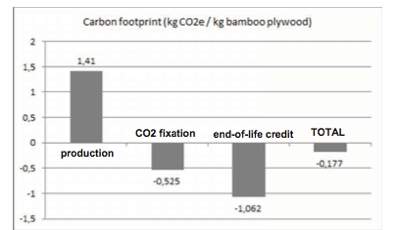
Figure 4 – Carbon footprint (kgCO2/kg) for carbonized 3-layer laminated bamboo board (van der Lugt, et al., 2012)
2.2 Engineered bamboo
Engineered bamboo, much like engineered timber, is a term referring to any products that utilise smaller sections of bamboo to form composite sections. The sections that are formed are of particular interest due to the standardisation of form and relatively low variability in material properties that can be achieved (Sharma, et al., 2015b).
Two key forms of engineered bamboo are laminated bamboo and bamboo scrimber. Laminated bamboo is formed by splitting the culm and planing it into regular, rectangular laminae. The laminae are then treated by bleaching or caramelisation and glued together under pressure (Sharma, et al., 2015b). Caramelised bamboo is treated with pressurised steam at 120-130o, which caramelises the sugars within the bamboo, whereas bleached bamboo is much paler in colour, and is treated in a bath of hydrogen peroxide at 70-80o (Sharma, et al., 2015a). Bamboo scrimber is formed by splitting the culm and crushing the material into fibre bundles. The bundles are then saturated in resin and compressed to form the desired section. Figure 5 is an image of these products, with bamboo scrimber on top of the stack, the lighter bleached bamboo beneath and caramlised bamboo on the bottom (Sharma, et al., 2015b).
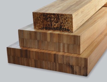
Figure 5 – Bamboo scrimber, bleached laminated bamboo and caramelised laminated bamboo (Plyboo, 2017)
Laminated bamboo is less dense than scrimber, due to the lack of crushing, and utilises less natural material. Van der Lugt (2008) states that laminated bamboo uses only around 30% of the natural material, compared to 80% for scrimber. The majority of offcuts resulting from both processes are subsequently burnt for energy, reducing waste.
Mahdavi et al. (2011) compiled a comparative review of 4 separate studies on the mechanical properties of a certain type of engineered bamboo. The study compares 2 sources concerning laminated bamboo, by Rittironk & Elnieri (2007) and Sulastiningsih & Nurwati (2009), 1 source for bamboo scrimber, by Lee, et al. (1998) and 1 source for rolled bamboo, by Nuguroho & Ando (2001). Rolled bamboo differs from scrimber predominantly in the manner with which its pressed, providing a generally denser material than scrimber. The comparison showed the method developed by Lee, et al. (1998) to provide a slightly higher MOR than that of the other methods. Otherwise comparable properties were found in all four studies. The authors highlighted several potential challenges to be dealt with before any engineered bamboo products can be used as a wood alternative. Key issues included difficulties in bonding bamboo with adhesives, the difficulty in forming suitable connections, the increased cost of bamboo once processed and the lack of formal codes or standards.
Sharma et al. (2015) also investigated the difference in mechanical properties between laminated bamboo and bamboo scrimber. The study uses Moso bamboo products, comparing the results to published data on the properties of Sitka spruce and Douglas Fir LVL. All the samples were tested to failure under four-point bending. The bamboo scrimber tended to fail on the tension face at mid-span whilst the laminated bamboo failed in longitudinal shear. Bamboo scrimber exhibited slightly higher strengths in flexure, with the increase attributed to the densified fibres within the members. Both materials performed significantly better than spruce or LVL. The study found a MOR for scrimber and laminated bamboo of 77-83 MPa and 119 MPa respectively. When compared to Spruce and Douglas-Fir LVL, 67 MPa and 68 MPa respectively, the engineered bamboo products are shown to not only be suitable for replacing wood products, but also for use in strengthening.
A comprehensive review of the literature was also conducted by Sharma et al. (2014), which includes data provided by two manufacturers of engineered bamboo. It is stated that, of the studies currently available, both bamboo products have properties that are comparable or exceed that of structural timber. The values presented in the study do however show large variation, and it is concluded that there is a need to standardise testing methods in order to form a suitable knowledge base for both products. Within the collected data the MOR for scrimber ranged from 54-266 MPa and from 39-145 MPa for laminated bamboo.
2.3 Laminated bamboo-timber hybrid sections
2.3.1 Glue laminated timber and laminated bamboo
Sinha and Clauson (2013) assessed the effect of laminated Moso bamboo adhered to the top and bottom faces of a glue laminated timber core. The timber core was formed of 3 Douglas fir studs of 38 x 142.5mm to give an overall section of 133.5 x 190mm. Two different resins, Isocyanate and phenol-resorcinol-formaldehyde were applied and compared. It was found that the hybrid beams out-performed 100% wooden beams with their MOR, however they presented lower MOE values. The adhesive was also found to significantly affect strength of the beams, with the isocyanate resin out-performing the PRF. The typical failure mode is shown to be shear failure in the wood, suggesting the benefits of the laminated bamboo reinforcement was not fully utilised.
Building upon this study, Chen et al. (2016) tested a total of 576 samples with varying orientations of bamboo veneer lumber and laminated poplar. Chizu bamboo and poplar veneers were immersed in phenol-formaldehyde and pressed into the lay-ups shown in Figure 6. The results showed that, as the ratio of bamboo to wood increased, so did the density, MOR and MOE. It was also found that when the bamboo veneers were located on the top and bottom layers the stiffness and strength improved by around 20%. It is interesting to note that, conversely to the study by Sinha and Clauson (2013) and as expected, not only the MOR but also the MOE increased when bamboo laminates are placed on the top and bottom faces.
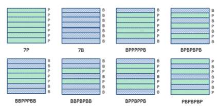
Figure 6 – Lay-ups of hybrid beams (Chen, et al., 2016)
The samples were tested under 3 point bending, with the main failure modes found to be:
- Crushing and fibre tearing, especially in softwood laminae
- Fibre fracture on the tension face
- Delamination between layers.
It is clear that where crushing has occurred shear deformations will have reduced the flexural capacity of the beam. This may have been avoided by using a 4 point bending test. It is also clear that the choice of adhesive in such tests is vital in order to fully utilise the bamboo laminates.
2.3.2 Sawn timber and laminated bamboo
As shown by the 2 studies by Sharma, et al. (2015) the increase in the mechanical properties of engineered bamboo products shows siginificant potential for use in reinforcing timber, especially poorly graded species. Amino (2003) studied the conception and feasibility of bamboo-precocious wood composite beams. In the study the author discusses the feasibility for construction, technical performance and economic viability of such a beam. The study suggests the use of woods such as poplar, eucalyptus and balsa, which grow in abundance in tropical countries but are typically ignored for construction due to their mechanical weakness. Quoting figures for the MOE of Moso bamboo at around 12.5 GPa and 6.5 GPa for Poplar, it is suggested timbers should be reinforced symmetrically, top and bottom, with laminated bamboo.
The author states that it is vital to reinforce the top and bottom of the beam in order to effectively exploit the mechanical advantages of the bamboo. They continue to predict that the reinforcement will prevent compressive rupture of the core and the beam will continue to bear load until brittle tensile rupture of the bamboo occurs. However, as in reinforced concrete design, a more ductile failure tends to be preferable as it allows identification and repair of over stressed members before catastrophic collapse. As stated by Sharma et al. (2015) laminated bamboo only exhibits small audible micro cracks and no visible cracks before failure. Taking this into account, allowing the slightly more ductile and obvious failure of timber to occur may be safer for use in construction.
Platt (2015) investigated repairing damaged timber members with laminates of bamboo. Timber is traditionally retrofitted using steel plates adhered or bolted to the tension face of the beam, however the large discrepancy between the stiffness of steel and timber can heavily increase the overall stiffness of the member and alter the load paths within the system. In this study it is noted that, as bamboo and wood have comparable moduli of elasticity, this problem would be alleviated.
Samples of 140x89x2743mm were prepared, with a 152x51mm notch on the tension face at mid span. Samples then had a single layer of bamboo laminate bolted across the notch with varying bolt layouts. Control samples of unreinforced notched beams and un-notched beams were also tested for comparison. The study found that the addition of bolted bamboo laminae improved the load carrying capacity modestly and that the MOR of the un-notched beam was greater than 50MPa but significantly less once notched. The bamboo laminate resulted in around 20% of the lost capacity being restored. It was concluded that engineered bamboo strip material represented a viable alternative for tensile reinforcement of timber beams.
Another thesis, this time by Archer (2016) looked at the flexural strength of varying depths of bamboo laminate on the top and bottom faces of a Sitka spruce core. The proportions of timber to bamboo used in this study are given in Table 2.
Table 2 – 3 Hybrid sections and solid sections of each material (Archer, 2016)
A total of 6 samples of each percentage of bamboo were prepared, 3 with bleached laminated bamboo and 3 with caramelised bamboo, in order to provide a comparison between the two treatments. Archer (2016) however concludes that this sample size was not sufficient to draw confident conclusions.
All specimens had a cross section of 50x50mm and were tested to failure under four-point bending. The study found the hybrid sections of bleached bamboo tended to have a higher MOR and MOE, despite testing on the full bleached and caramelised sections giving contradictory results. Despite this, the results clearly show that the hybrid sections had a significantly higher MOR when compared to pure timber.
It was also found that the bamboo showed catastrophic, brittle collapse, as with the other studies discussed. Most failures occurred in splitting of the fibres on the tension face or in delamination. Archer (2016) states that the timber gave several minutes of warning before collapse.
2.4 Composite beam behaviour
For the purpose of this study a simplified plane stress condition has been utilised in order to predict the behaviour of the composite beams. As stated by Bodig and Jayne (1993) the glue layer to contributes to around 1% of the volume of the composite, therefore it is also assumed that the contribution of the glue line will be negligible. The plane stress condition assumes homogenous properties within each laminae, strain at material interfaces is compatible and that plane sections remain plane during bending. As a four-point bending test has been used in this study, the vast majority of the specimen is subjected to pure bending and the assumption that plane sections will remain plane is likely to remain valid throughout much of each test.
2.5 Summary
As shown, the advantageous mechanical properties of laminated bamboo make it suitable for consideration in the reinforcement of weaker softwoods, such as Sitka spruce. As expected, the carbon emissions related to the production and transportation of laminated bamboo are higher than locally sourced sawn softwood, especially when considering its use in mainland Europe. It can however be shown that companies such as Moso International BV produce carbon neutral laminated bamboo material, even when transported to Europe. It is also worth noting that bamboo plantations also have several other beneficial impacts on the surrounding environment, such as providing habitats and stabilising land mass.
Previous studies on the production of hybrid timber-bamboo beams have produced promising results, especially as shown in the studies by Archer (2016) and Chen et al. (2016). Both studies found that using bamboo laminates on the top and bottom face increased the MOR of the samples, however it was noted that failure almost always occurred on the tensile face.
Using the plane stress condition, reinforcing the top and bottom faces with bamboo provides a larger predicted MOR. However, as laminated bamboo remains more expensive than softwood and failure of such samples tends to occur on the tension face, this study will look into whether reinforcing only the tension face can provide a more economically efficient hybrid beam.
3.0 Methodology
3.1 Materials
Bleached laminated bamboo board of Phyllostachys Pubescens, or Moso bamboo, was sourced from Moso International BV in Amsterdam, Netherlands. The board was purchased in 1200x19x2400mm single, side pressed sheets. European Sitka spruce was sourced from Avon Plywood in Keynsham, Somerset in sizes of 48x70x1200mm and 75x70x1200mm. At the time of purchase the bamboo product was approximately 5.8 times more expensive per unit volume than the Sitka spruce.
3.2 Section specification
In order to fit within time and budget constraints, a total of 18 samples were tested. For this study each sample is referred to with respect to the depth of bamboo in the section and the chronological order in which it was tested. For example, B-19-3, has a 19mm bamboo laminate and was the 3rd of the 19mm hybrids to be tested.
As the mechanical properties of European grown Sitka spruce are well documented it was decided a smaller sample size of 3 would be suitable. The hybrids B-15 and B-19 were chosen in order to draw a direct comparison between the doubly reinforced beams in the study by Archer (2016) and this study. Both samples were given the same proportion of tensile reinforcement, as the former study, with the compression reinforcement omitted.
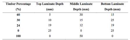
The hybrid sections B-15 and B-19 were analysed using the plane stress condition, with the relevant material parameters taken from the study by Sharma et al. (2015). This predicted that almost all of the timber would be acting in compression before the bamboo reached its yield strength. Therefore the final hybrid beam, B-10, was designed to have a reduced proportion of bamboo. Hybrid B-10 was designed so that a significant portion of the timber was still acting in compression, however still allowing a reasonable amount of timber to yield in compression. It was designed in this manner so that the beam would continue to give ample warning, through visible and audible cracking, before complete failure. Table 3 outlines the samples that were prepared.
Table 3 – Timber and hybrid samples prepared
| Specimen | No. specimens | Depth of bamboo laminate (mm) | Depth of timber laminate (mm) |
| B-0 | 3 | 0 | 50 |
| B-10 | 5 | 10 | 40 |
| B-15 | 5 | 15 | 35 |
| B-19 | 5 | 19 | 31 |
3.3 Specimen preparation
The bamboo and timber sections were initially sawn in the timber workshop at the University of Bath. The initial dimensions of each sample included an allowance for the misalignment of the laminates once they had been glued. Each of the hybrid beams were laminated using Purbond HB S309 polyeurethane adhesive, to the guidelines set out in the manufacturer’s technical data sheet.
The surfaces to be glued were cleaned and moistened with a wet sponge. The glue was then applied to the timber laminate manually, using a Purbond through-feed spreader, at a rate of 180 g/m2. The bamboo laminate was laid on top and pressed with a series of manually tightened clamps under a pressure of 0.6 MPa. The samples were pressed in sets of 3 for 4 hours in the Structures Laboratory at the University of Bath, at an average temperature of 17c. This process is outlined in Figure 7.
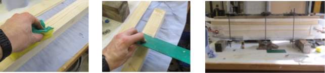
Figure 7 – Lamination process
The samples were then planed to give an overall section of 50x50x1200mm and left to cure for 2 weeks before testing. Due to a mistake during the final planing of the samples, all B-10 samples and sample B-15-2 were laminated again with Sitka spruce to provide the correct overall dimensions. The laminates were glued and pressed using the same procedure, again allowing a 2 week curing period before testing.
The volume and mass of each sample was recorded and the density determined from these values. The volume was measured with a vernier calliper and rule to a precision of 0.1mm. The mass of each sample was measured of a scale to a precision of 0.01g.
3.4 Test procedure
To determine the flexural properties of each beam, four-point bending tests were carried out to the guidelines set out in BS 373. The tests were predominantly carried out on the 200 kN Mayes Universal hydraulic testing frame at the University of Bath. Samples B-0-3, B-15-5 and B-19-5 were tested on the 100 kN Dartec Universal hydraulic testing frame following a malfunction in the 200 kN frame.
As stated in BS 373 (1999), where an accurate method for determining the modulus of elasticity is required, the four-point bending method should be used. This method subjects the beam to a uniform bending moment along a significant proportion of the beam, allowing the modulus of elasticity to be calculated without making adjustments for shear deflections.
On both machines the support points were set up with a clear span of 914.4mm, with two loading points positioned 152.4mm from each support as shown in Figure 8.
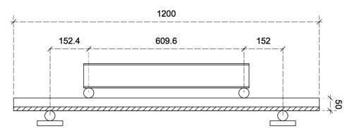
Figure 8 – Four point bending set up to BS 373
The loading head applied a constant deflection rate of 3.3mm/min until eventual failure, with the deflection recorded at each loading point and at mid span for all samples. An image of the set up on the 100 kN testing machine is shown in Figure 9.
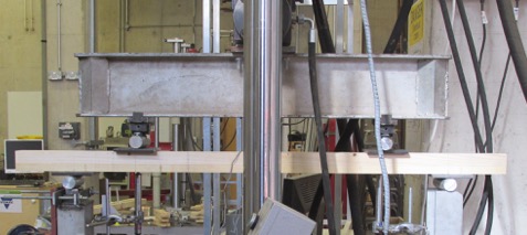
Figure 9 – Four point bending test set up on the 100kN universal testing machine
In addition, TML FLA 10-11 strain gauges were applied to the top and bottom face and neutral axis of samples B-0-3, B-10-5, B-15-5 and B-19-5. Gauges were applied with Cyanoacrylate adhesive and a resistance check was conducted once the soldering of wiring had been completed.
4.0 Prediction of results
4.1 Plane stress analysis
A plane stress analysis was utilised in order to predict the modulus of elasticity and modulus of rupture for each sample. The values used in this analysis were taken from the study by Sharma et al. (2015), and are provided in Table 4.
Table 4 – Material properties from Sharma et al. (2015)
| Material | Modulus of elasticity (GPa) | Tension parallel to grain (MPa) | Compression parallel to grain (MPa) |
| Bleached laminated bamboo | 10.2 | 124 | 55 |
| Sitka spruce | 8 | 59 | 36 |
As the modulus of elasticity of laminated bamboo is higher than that of Sitka spruce it was predicted that the addition of a bamboo laminate would make the hybrids stiffer than a comparable beam of Sitka. The hybrids in this study are however predicted to have a lower MOE than a doubly reinforced sample with the same proportion of tensile reinforcement, due to the lack of a further laminate on the top face.
The most significant difference is predicted to be the maximum load carrying capacity of the hybrid sections. Figure 10 presents the predicted stress distribution within each sample. This is shown at the limit of proportionality, which is assumed to be reached once the timber is at its compressive yield strength, and at failure, which is assumed to occur when the bamboo reaches its tensile yield strength.
As previously mentioned, the plane stress method relies on plane sections remaining plane. Once the timber surpasses its yield strength it starts behaving plastically and this assumption may no longer be true. It also relies on the deflection remaining small which is unlikely to be true at failure, due to the significant flexibility of bamboo. Therefore this prediction of the behaviour at failure should only be considered a rough estimation.
As can be seen in Figure 10, the much of the bamboo within samples B-15 and B-19 is under a very low bending stress. This would suggest that these samples present a less efficient use of the bamboo material. It is also clear that as the samples approach failure the stress distribution begins to represent that of reinforced concrete that has cracked in tension, in this case with the timber presenting an almost entirely rectangular stress block and the bamboo carrying the majority of the tension.
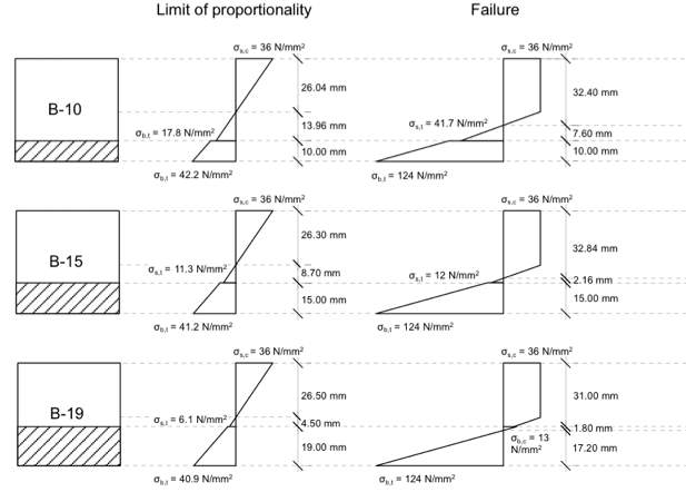
Figure 10 – Predicted stress distribution in hybrid samples
The stress distribution for each sample at failure was then used to provide an idea of the ultimate moment capacity of the beam. The distributions were simplified into a series of forces, acting through the centre of area for the section it represented. The tensile forces were then multiplied by their lever arm about the compressive force and summed to find an estimate of the moment capacity. An equivalent modulus of rupture was then determined using Equation 1:
σ= MyI
( 1 )
The results are summarised in Table 5.
Table 5 – estimated bending moment capacity and mor for hybrid samples
| Specimen | Moment capacity (kNm) | Corresponding MOR (MPa) |
| B-10 | 1.39 | 66.9 |
| B-15 | 1.56 | 74.9 |
| B-19 | 1.57 | 75.3 |
It can be seen that this estimates smaller increments in the increase of the moment capacity and MOR as the laminated bamboo laminate increases in depth to 19mm. This again suggests that the bamboo material in samples B-15 and B-19 will not be utilised as efficiently as the B-10 samples. The modulus of rupture for a full size sample of Sitka spruce containing defects is taken as 36 N/mm2 (Moore, et al., 2009a). This suggests 86% increase in the modulus of rupture for hybrid B-10 and an increase of 109% for hybrid B-19.
4.2 Adhesive shear strength
The technical data sheet for Purbond HB S309 (2013) states that the adhesive has a Type I classification in accordance with EN 15425 (2008). This prescribes a minimum mean tensile shear strength for a type I adhesive of 10 N/mm2 under A1 conditioning, which is most similar to the conditions in this test. Equation 4, from BS 373, provides the maximum horizontal shear stress at the centre of the cross-section. This only applies to the ends of each sample, as the central portion of the beam is subjected to pure bending and will be subjected to no horizontal shear stresses. Rearranging for F we can find the maximum force that the adhesive could support if it were positioned centrally in the cross section.
τ=3F4bh
( 2 )
Assuming each sample is exactly 50 x 50 mm, the adhesive can support a maximum allowable load of 33.3 kN. The timber and bamboo are expected to have yielded in bending by this point. This is also a conservative check, as the glueline is not positioned at the centre of the the cross section in any sample. Shear stresses reduce with increased distance from the centreline, meaning the glueline will be subjected to a lower stress than calculated. Shear failure of the glue is therefore not expected to be a limiting factor.
5.0 Results
In this section the results obtained from load, displacement and strain measurements are analysed and compared. This is achieved through plots of load-displacement and strain profiles, in addition to the calculation of material parameters, such as the modulus of elasticity and modulus of rupture.
The modulus of rupture (MOR), or maximum fibre stress, indicates the maximum bending stress within the sample before failure occurs. It is calculated using Equation 3, which is provided in BS 373:
MOR=3Fmaxabh2
, ( 3 )
where Fmax is the maximum load applied to the specimen, a is the distance from a support to the nearest loading point, b is the breadth of the cross section and h is the height of the cross section.
This differs from the modulus of elasticity (MOE) in that it is irrespective of deflection. The modulus of elasticity is a measure of the rate at which displacement increases with load before the limit of proportionality. The MOE is calculated based upon the 10% and 40% values of Fmax and their corresponding deflections. It is calculated using Equation 4, which is also derived from BS 373:
MOE= 3F40%-F10%aL24δ40%-δ10%bh3
, ( 4 )
where F40% and F10% are the forces at 40% and 10% of Fmax, L is the span length and 40% and 10% are the displacements corresponding to the values of F40% and F10%. All other values are as defined in Equation 1.
The results in this section do not include sample B-10-1 as this test appears to have produced an anomalous result. The beam appeared to have been loaded asymmetrically, causing the bearing at one loading point to progressively rotate out of plane. This resulted in significant localised fibre crushing beneath the left loading point, shown in Figure 11.
Figure 11 – Localised crushing beneath asymmetric loading
5.1 Comparison of hybrid sections
This section will compare the behaviour of the 3 sets of hybrid beams tested in this study. Each beam had an overall cross-section of 50x50mm, with varying depths of bleached laminated bamboo. The depths of laminated bamboo tested were 10mm, 15mm and 19mm, referred to as B-10, B-15 and B-19 respectively. Table 6 presents the average MOE and MOR for the 3 sets of hybrid beams.
Table 6 – Mean MOR and MOE of hybrid samples
| Specimen | Modulus of rupture (MPa) | COV | Modulus of elasticity (GPa) | COV |
| B-10 | 66.9 | 0.06 | 11.8 | 0.08 |
| B-15 | 68.8 | 0.11 | 11.1 | 0.07 |
| B-19 | 70.1 | 0.05 | 11.5 | 0.08 |
5.1.1 Modulus of rupture
It can be seen that the mean modulus of rupture increases as the proportion of bamboo increases. It is however a relatively modest increase, samples B-10 and B-19 have a 90% increase in the volume of bamboo which yields only an increase in the MOR of only 4.8%. It is also worth noting that samples B-15 and B-19 are found to have a mean MOR of lower than the value predicted using the plane stress analysis.
5.1.2 Modulus of elasticity
As shown by the values in Table 6 there appears to be no clear relationship between the proportion of bamboo and the mean MOE. Despite this lack of correlation, it can be seen that the 3 hybrid sets show very similar values for their mean MOE. Also, contrary to the prediction that a higher proportion of bamboo would yield a higher stiffness, the highest mean MOE is exhibited by the B-10 samples.
5.1.3 Load-displacement plot
Figure 12 presents the load displacement plot for samples with the maximum, minimum and median MOR within each hybrid set. Each sample expresses a clear section of proportionality, followed by the slope beginning to plateau, before a sudden brittle collapse. The divergence of the plots within the limit of proportionality further expresses the variability in the stiffness of the hybrid beams. Beams B-10-5 and B-10-3 stand out, both with an MOE that is significantly greater than the rest of the samples. B-15-4 exhibits the shallowest line within the limit of proportionality, as well as failing at a much lower load than the other samples. This is in contrast to sample B-15-1 of the same hybrid set, which can be seen to fail at the highest load of 21.8 kN.
The B-19 samples and B-10 samples can be seen to exhibit less variable failure loads with a range of 2.4 kN and 3.4 kN respectively, compared to a range of 5.2 kN for B-15 samples. Figure 12 also shows the significant displacements that each sample underwent before failure, with each beam continuing to resist load well after the limit of proportionality. The largest deflection was achieved by sample B-19-2, which deflected 67.9mm at midspan.
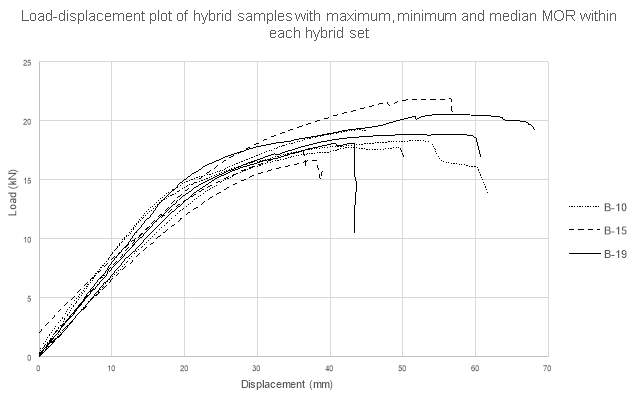
Figure 12 – Load-displacement plot of maximum, minimum and median MOR hybrid samples
5.1.4 Density relationship
As the laminated bamboo material is denser than the Sitka spruce, it is expected that as the density increases so will the stiffness and strength of the hybrid. As can be seen in Figure 13, the majority of samples show a slight positive correlation between their density and modulus of rupture. The two obvious outliers again are samples B-15-1 and B-15-4. As both samples deviate from this plot, it does not appear as though the difference in modulus of rupture is related to the density of either laminate. Conversely, Figure 14 appears to show no correlation between the calculated values of MOE and density.
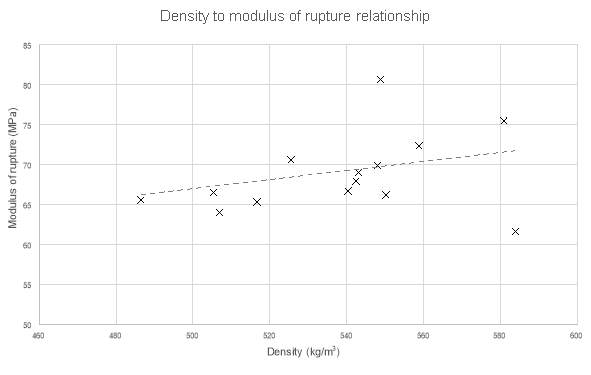
Figure 13 – Relationship between density and modulus of rupture
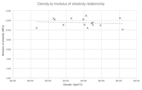
Figure 14 – Relationship between density and modulus of elasticity
5.1.5 Discussion
The results from this comparison appear to show that, as expected, as the bamboo laminate increases in depth, so does the modulus of rupture of the beam. The small percentage increase in the mean MOR that is seen between samples B-19 and B-10 would however suggest that the laminated bamboo material is not used as efficiently in the deeper laminates. Considering the higher cost of laminated bamboo, a 90% increase in the volume of material is unlikely to warrant only a 4.8% increase in strength.
The calculated values of the MOE presented no clear correlation between bamboo depth and hybrid stiffness, whilst the overall mean values for each hybrid set were very similar. This would suggest that the bamboo depth has little effect and the MOE of each sample was more heavily affected by the natural variability of the timber. The use of a further bamboo laminate on the top face may have mitigated this effect. Figure 14, also showed a lack of correlation between the MOE and the density of the sample, which further suggests that variations in the stiffness of the sample were driven by the timber.
It is also worth noting the much smaller coefficients of variation expressed by the hybrid samples in this study. This would suggest the bamboo laminate acts to normalise the mechanical properties somewhat, improving their predictability.
5.2 Comparison of hybrid sections to Sitka spruce
This section will look to compare the behaviour and mechanical properties of the hybrid beam sections with that of Sitka spruce. Comparisons will be drawn between the data collected in this study and published data of the MOE and MOR of Sitka spruce. Table 8 provides the mean MOE and MOR for the hybrid and pure Sitka spruce beams used in this study, in addition to published data from two sources. The study by Lavers (1983) presents the mechanical properties of a small clear (SC) sample of Sitka, which contains no defects such as knots. Moore, et al. (2009a) present data for a full-size (FS) specimen containing defects.
Table 7 – Mean MOE and MOR of Sitka spruce and hybrid samples
| Specimen | Reference | Modulus of rupture (MPa) | COV | Modulus of elasticity (GPa) | COV |
| Hybrid B-10 | Present study | 66.9 | 0.06 | 11.8 | 0.08 |
| Hybrid B-15 | 68.8 | 0.11 | 11.1 | 0.07 | |
| Hybrid B-19 | 70.1 | 0.05 | 11.5 | 0.08 | |
| Sitka spruce B-0 | 40.2 | 0.23 | 14.0 | 0.23 | |
| Sitka spruce (SC) | (Lavers, 1983) | 67.0 | 8.1 | ||
| Sitka spruce (FS) | (Moore, et al., 2009a) | 36.0 | 7.9 |
5.2.1 Modulus of rupture
From the figures provided in Table 9 it can be seen that the MOR of the hybrid beams is consistently larger than the values calculated in this study and the study by Moore et al. (2009a). Hybrid B-10, with the lowest proportion of bamboo, exhibits an 86% increase in its modulus of rupture, when compared to the data published by Moore. Sample B-19 exhibits an equivalent increase in the MOR of 95%. The coefficient of variation within each sample set also clearly shows the hybrids to have a much less variable ultimate strength.
The modulus of rupture for each Sitka spruce sample in this study is provided in Table 9. The MOR for samples B-0-2 and B-0-3 provided comparable results to the study by Moore et al. (2009a). Sample B-0-1 yields a much larger value, which appears to have been caused by a large knot close to midspan.
Table 8 – MOR for Sitka spruce samples in this study
| Specimen | Modulus of elasticity (GPa) |
| B-0-1 | 17.7 |
| B-0-2 | 12.5 |
| B-0-3 | 11.8 |
5.2.2 Modulus of elasticity
The mean MOE values in Table 8 suggest that the addition of the bamboo laminate generally affected a reduction in the modulus of elasticity of the samples. The beams with the largest 10 values of MOE are provided in Table 9, along with their respective density. It can be seen that there is no clear correlation between the depth of bamboo within the cross section, or to the overall density of the sample and the MOE. As with the MOR, the modulus of elasticity of sample B-0-1 was also found to be signifcantly larger than the other samples.
Table 9 – Maximum MOE values in this study
| Specimen | Modulus of elasticity (GPa) | Density (kg/m3) |
| B-0-1 | 17.7 | 495 |
| B-10-3 | 13.0 | 543 |
| B-0-2 | 12.5 | 496 |
| B-19-2 | 12.5 | 581 |
| B-19-1 | 12.4 | 526 |
| B-10-5 | 12.4 | 505 |
| B-10-1 | 12.2 | 538 |
| B-15-2 | 12.2 | 549 |
| B-0-3 | 11.8 | 511 |
| B-10-4 | 11.5 | 550 |
The hybrid samples in this study do however show a significant increase in stiffness when compared to published data on Sitka spruce. When compared to results collected by Lavers (1983), hybrid B-10 exhibits a mean MOE 46% larger than that of a clear sample of Sitka spruce.
5.2.3 Load-displacement plot
In order to compare the load displacement behaviour of the hybrid and spruce samples, the sample with the median MOR from each set is plotted in Figure 15. The similarities in MOE are again highlighted here, with all the samples except B-10-3 showing a very similar gradient within the limit of proportionality. It is also clear that the hybrid samples not only fail at a much higher load than the spruce, but also exhibit a large region of plastic behaviour. This is compared to a virtually non-existent plastic region expressed by the timber sample, which yields almost immediately after the limit of proportionality. After this initial yielding, the spruce continues to yield at lower loads until eventual collapse. Each hybrid sample exhibits plastic behaviour until a sudden, brittle collapse of the bamboo.
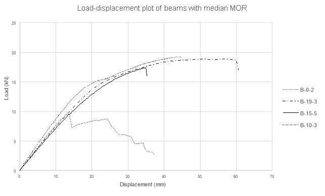
Figure 15 – Load displacement plot of median MOR samples
5.2.4 Discussion
This comparison again makes it clear that the B-10 samples appear to present the most efficient use of the bamboo material. Hybrid B-10 and B-19 affected an 86% and 95% increase in the MOR respectively when compared to a sample of spruce. For commercial purposes a further 9% increase in capacity is unlikely to be sufficient to justify almost doubling the volume of bamboo within the cross section.
The results recorded during the testing of the 3 spruce samples present a range of 16.8 MPa. This large range gives an indication of the difficulties in predicting the behaviour of defects in sawn timber. The hybrid samples generally presented a much smaller range and a significantly higher value of MOR. This is appears to be caused by the bamboo material bridging tension cracks in the timber, preventing their propagation. As previously discussed, the bamboo is more homogenous and stronger in tension than spruce, explaining the higher MOR and smaller range.
Contrary to predictions that the addition of laminated bamboo would increase the stiffness of Sitka spruce, the results in this study showed a clear reduction. The mean MOE for the Sitka is heavily increased by sample B-0-1, however even without this sample the mean MOR for the spruce remains higher than that of the hybrid samples. This would seem to suggest that these spruce samples are stiffer than the laminated bamboo used in this study. Conversely, comparisons to published data showed the hybrids to be significantly stiffer than Sitka spruce. This disparity may be due to the Sitka sourced for this study exhibiting a larger stiffness, or that the sample size of 3 Sitka beams in this study was not sufficient to provide an accurate value for the modulus of elasticity. Another possibility is that the methods used in this study have provided an artificially high stiffness.
5.3 Comparison to doubly reinforced hybrids
In this section the results obtained for the hybrid beams in this study will be contrasted with the data found by Archer (2016). In order to allow a direct comparison, several steps were taken to reduce the number of variables. The raw materials and adhesive were sourced from the same providers and hence the lamination process was carried out to the same manufacturers guidelines. Samples were then tested to BS 373, as in the previous study.
According to the plane stress condition, the addition of further material of higher MOE should increase the overall stiffness of the section. As the compressive yield strength of laminated bamboo is higher than Sitka, it would also predict a higher overall MOR for the section. Archer (2016) stated that, at failure, almost all samples failed through tearing of the bamboo material in tension, with little or no mention of failure of the bamboo under compression. This section will therefore look to determine the impact of the compression bamboo laminates.
The section will focus on samples B-15 and B-19, as these samples contain the same proportion of tensile reinforcement as samples in the aforementioned study. As mentioned in the literature review, this study also tested samples with caramelised laminated bamboo. The results for caramelised bamboo hybrids will be ignored for the purpose of this comparison, as the study found there to be a clear difference in mechanical behaviour. Figure 16 gives a graphical representation of the beams that will be directly contrasted.
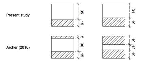
Figure 16 – Singularly and doubly reinforced sections to be compared
There can be a large variability in the mechanical properties of sawn softwoods, due to several factors, such as age, moisture content and defects. Therefore for a direct comparison to be drawn it should first be checked that the properties of the samples of Sitka spruce in each study are comparable. Table 10 provides the mean MOE and MOR recorded in both studies. Sample B-0-1 from this study is discounted in the calculation of the mean. As discussed in Section 4.3.1 this result does not appear to be representative of the behaviour of the rest of the samples due to the large knot near midspan. The figures in Table 10 show the Sitka spruce in this study to have a larger MOR but a lower MOE. The material properties are however within a reasonable range and are considered suitable for comparison. The slight difference in properties will also be considered in further analysis.
Table 10 – Mean MOR and MOE for Sitka in this study and Archer (2016)
| Specimen | Reference | Modulus of rupture (MPa) | Modulus of elasticity (GPa) |
| Sitka spruce | Present study | 35.1 | 12.2 |
| (Archer, 2016) | 32.9 | 12.4 |
5.3.1 Modulus of rupture
Table 11 presents the mean MOR and MOE for each sample. It is clear that the samples all present comparable values for the MOR. However, contrary to predictions, the MOR of the singularly reinforced samples in this study was consistently higher. The largest discrepancy was found in the samples with 19mm of tensile reinforcement, which saw an increase of 8.7% in the MOR.
Table 11 – Mean MOR and MOE values for hybrids in this study and Archer (2016)
5.3.2 Modulus of elasticity
The results for the MOE present values that more closely reflect the predictions made using the plane stress analysis. Both doubly reinforced samples present a larger stiffness, with the results for the 15mm reinforced samples suggesting that the addition of a 5mm compression laminate affects a 33% increase in the MOE.
The samples with 19mm of tensile reinforcement showed a 4% increase in the MOE with the addition of a 19mm compression laminate. Considering the compression laminate is significantly larger in this case, the smaller percentage increase is surprising. It is also worth noting that, despite having a smaller proportion of bamboo within the cross section, the samples with 15mm of tensile reinforcement were found to be stiffer in both studies.
5.3.3 Discussion
The results of the comparison appear to confirm the prediction that a singularly laminated hybrid has a lower stiffness than a doubly reinforced beam with the same depth of laminate on the tensile face. Both doubly laminated samples express a clear increase in the mean MOE, suggesting the second laminate is effective in improving the stiffness of these hybrids.
It can also be seen that the MOR does not appear to be significantly affected by the presence of a second laminate on the top face, with this comparison suggesting it actually reduced the capacity. The increase in the MOR seen between this study and Archer (2016) may be in part be explained by the fact that the spruce was to have a mean MOR 17% larger than that used in Archer’s study. It is also possible that the relatively small sample sizes in each study has produced results that do not accurately represent the behaviour of these hybrids.
This comparison presented several unexpected results, making definite conclusions difficult to draw. It is clear that the differences in the mechanical properties of Sitka may have had a significant impact on these results and ideally these two studies would have been carried out concurrently, with materials sourced at the same time.
5.4 Strain analysis
Strain gauges were applied to the top and bottom face and neutral axis of 4 samples. One sample was selected at random from each set and tested in the same manner as the other samples. Where the strain gauge was not positioned exactly at the neutral axis, the actual distance from the bottom edge of the sample was recorded in order to accurately plot the strain profile.
5.4.1 Maximum tensile fibre strain
Table 12 provides the tensile strain at Fmax for each strain gauged sample, along with the value of Fmax for each respective sample. Despite the small sample size it can be seen that there is a definite increase in tensile strain exhibited by the reinforced samples.
Table 12 – Tensile fibre strain at Fmax
| Sample | Fmax (kN) | Tensile strain at Fmax |
| B-0-3 | 18.2 | 0.0012 |
| B-10-5 | 26.3 | 0.0076 |
| B-15-5 | 17.8 | 0.0057 |
| B-19-5 | 21.4 | 0.0095 |
5.4.2 Strain profiles
Figure 17 represents the experimental strain data for each of the 3 hybrid samples at load increments of 3, 6 and 9 kN. From load-displacement plots this range was determined to be within the limit of proportionality for all hybrid samples. Each plot appears to present a roughly linear distribution of strain throughout the beam cross-section.
The samples all show an apparent deviation of the neutral axis from the mid-height of the cross section, especially by samples B-10-5 and B-19-5. Prior to carrying out the experiments it was predicted that the stiffer bamboo material would shift the neutral axis below mid-height of the cross-section, however as shown in Figure 17 the neutral axis appears to be positioned above mid-height.
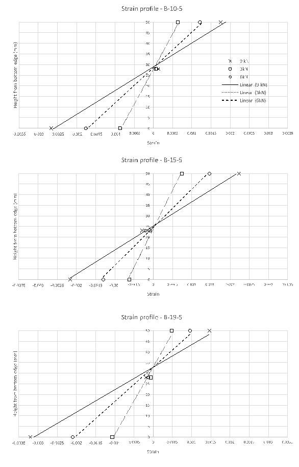
Figure 17 – Hybrid strain profiles
Once the limit of proportionality had been exceeded, the strain profiles of each sample show the neutral axis shifting upwards towards the top face of the beam. Sample B-15-5 is shown in Figure 18 as an example of this behaviour. Between 9 kN and 13.5 kN the neutral axis appears to shift up slightly, however by 18kN, just before failure, there is a clear shift of the neutral axis upwards.
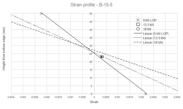
Figure 18 – Strain profile beyond limit of proportionality
5.4.3 Discussion
As shown by the large increase in tensile fibre strength, the laminated bamboo allows a much higher deflection and fibre stress within hybrid sample. This appears to be due to two key factors, bamboo’s ability to undertake significant deflection before yield and, as discussed, the bamboo material bridging tension cracks in the spruce, preventing propagation and the resulting collapse.
Due to the relatively linear strain profiles expressed by each sample it also appears that the polyeurethane adhesive provided a sufficient bond for the section to act in a fully composite manner. It therefore follows that the assumption of strain compatibility at the bamboo-wood interface is reasonable.
The apparent deviation of the neutral axis upwards within the limit of proportionality suggests that either the timber material has a higher modulus of elasticity than assumed during the initial analysis, or that strain gauges were placed close to wood defects with a higher stiffness. The conclusion that the timber has a higher stiffness than initially assumed would also be in line with findings in Sections 5.2 and 5.3.
The movement of the neutral axis upwards after the limit of proportionality appears to be similar to the behaviour exhibited by reinforced concrete. Once the concrete has cracked in tension the reinforcement bar supports the tension forces, increasing the strain in the reinforcement and pushing the neutral axis upwards. This similarity may suggest that the bamboo acts much like standard reinforcement.
As this analysis was limited to one repeat per sample, these values only provide an indicative assessment of the strain behaviour in each hybrid beam. Ideally further repeats would be conducted in order to fully understand the impact of the reinforcement in terms of strain.
5.5 Failure modes
As expected, the failure of all 3 unreinforced samples occurred in tensile cracking of the bottom face. No samples showed signs of yield in compression on the top face prior to failure. It is also worth noting that each sample failed unsymmetrically, with each failure propagating from a wood defect. This again highlights the difficulty in predicting the behaviour of wood defects, such as knots, in timber. A photo of each failed sample is provided in Figure 19. It can be seen that B-0-1, which was found to have significantly larger mechanical properties, appears to have failed in wood shear, propagating from a centrally located defect. Conversely B-0-2 and B-0-3 have failed in tension, with cracks propagating from a defect positioned on or near to the bottom face of the sample.
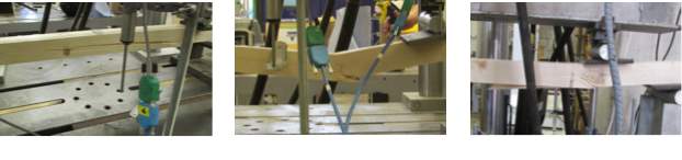
Figure 19 – Failure of timber samples
Failure within the hybrid samples occurred in standard bending related failure modes, except for sample B-10-1 which failed in fibre crushing beneath a load point. The failures experienced by the remaining samples can be categorised into four clear categories, as expressed in Figure 20. Mechanisms 1 and 2, where fibre tearing has occurred, can be seen to have failed in between the supports, where the samples are subjected to pure bending. The tearing of fibres on the bottom face reflects where tensile bending stresses have exceeded the tensile yield strength of the material, causing collapse. Conversely the failure shown in mechanisms 3 and 4 extend past load positions with a long horizontal crack, suggesting that failure occurred under the high shear stress exerted between the load points and supports.
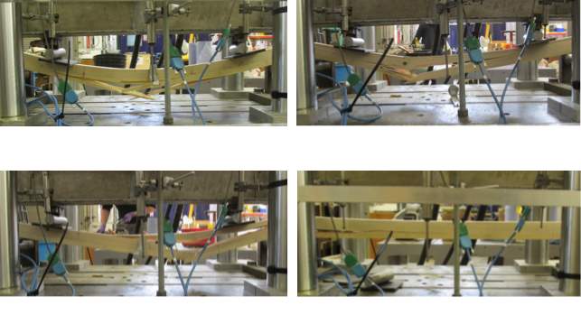
Figure 20 – Failure modes in hybrid Samples
Before failure all samples exhibited several compression cracks forming along the top face, which steadily propagated through the cross section. The beginning of these cracks clearly expressed the point at which the samples entered their semi-plastic region, as the top surface of the wood failed and began deforming plastically, whilst the bamboo remained completely elastic.
Samples failing under modes 2 and 3, where failure propagated from a wood defect, all exhibited a reduction in mechanical properties. The MOE and MOR of each sample failing under these mechanisms are listed in Table 13, along with the deviation of each value from the mean of its respective hybrid set.
Table 13 – MOE and MOR of samples failing under mechanism 2 and 3
| Sample | Modulus of elasticity (GPa) | Hybrid mean (GPa) | Deviation from the mean (GPa) | Modulus of rupture (MPa) | Hybrid mean (MPa) | Deviation from the mean (MPa) |
| B-10-2 | 16.0 | 18.2 | -2.2 | 65.6 | 66.9 | -1.3 |
| B-10-4 | 17.8 | 18.2 | -0.4 | 66.2 | 66.9 | -0.7 |
| B-15-4 | 15.6 | 17.1 | -1.5 | 61.6 | 68.8 | -7.2 |
| B-15-5 | 17.1 | 17.1 | 0.0 | 65.3 | 68.8 | -3.5 |
| B-19-1 | 16.0 | 17.8 | -1.8 | 70.6 | 70.1 | +0.5 |
| B-19-5 | 17.8 | 17.8 | 0.0 | 66.7 | 70.1 | -3.4 |
From Table 14 it is clear that the defects that caused failure mechanisms 2 and 3 generally caused a reduction in the mechanical properties of the sample. The samples containing a wood defect close to the top surface generally failed under mechanism 2. Weaker material surrounding the defect appeared to crush more readily, which caused the eventual tensile tearing of the bamboo fibres beneath it. A laminate of bamboo on the compression face of the sample may have mitigated somewhat against this mechanism. Conversely a laminate of bamboo on the top face of the beam is unlikely to have affected a significant reduction in the occurrence of shear in the wood.
In Section 4.0 the shear strength of the glue was checked against the manufacturers specification of tensile shear strength and found to be sufficient. Therefore delamination is likely to have occurred due to human error in the gluing process, or wood defects along the glue line causing stress concentrations. Despite this, experimental results show that this mechanism caused no major detrimental effects on the mechanical properties of the samples.
6.0 Conclusion
This dissertation aimed to determine the behaviour of a hybrid beam of Sitka spruce reinforced with a single layer of laminated bamboo. It was hoped that the results would present this method as an effective, environmentally friendly alternative for the strengthening of poorly graded timber. The study investigated laminated bamboo depths of 10mm, 15mm and 19mm with the spruce planed to give each hybrid an overall cross section of 50x50mm.
Through a literature review, the laminated bamboo was found to have several advantageous properties when compared to Sitka spruce. A high mechanical strength in most orientations, good homogeneity and rapid growth of the raw material make it an extremely useful resource. In addition it was also found that, if sourced from certain providers and disposed of correctly, the material can be considered carbon neutral.
Following a plane stress prediction of the hybrid behaviour, five samples of each hybrid and three control samples of Sitka spruce were tested to failure under four point bending. As expected, increasing the depth of the bamboo laminate within the cross section appeared to cause an increase in the modulus of rupture. It was found that the 10mm laminate presented the most efficient use of the material, exhibiting a mean modulus of rupture 86% larger than that of spruce. The results in this study were also compared to those found by Archer (2016) for Sitka spruce strengthened with bamboo laminates on both the top and bottom face. This comparison showed a reduction in the MOR of the doubly reinforced samples, suggesting the compression has no beneficial impact on the MOR.
The results for the modulus of elasticity were more variable and offered no clear relationship between the depth of bamboo laminate and the stiffness. The hybrids in this study in fact presented a lower modulus of elasticity than the pure spruce samples, suggesting the bamboo laminates reduced the overall stiffness of the section. When compared to the hybrids in Archer’s study the single laminate hybrids in this study also showed an appreciable reduction in stiffness, suggesting the compression laminate has a large effect on the overall stiffness.
Focusing purely on the results of this study would suggest the applications of this method would be limited to where an increase in strength is required, whilst stiffness was not an issue. This is rare in timber design as member selection tends to be driven by deflection limits and not ultimate strength. Applications where stiffness is provided by a separate entity provide some scope for this method. For example the production of a timber composite floor unit, where further stiffness could be provided by the floorplate. Alternatively this method could be used as a localised strengthening technique for structural systems with a high inherent stiffness. Examples include continuous beams and embedded beams, which could be reinforced at midspan and at supports. Although this could be difficult to design into a customised structure, this system may have scope for use in prefabricated units.
The large deformation exhibited by the hybrid samples in this study also presents the possibility for use in structures which require the ability to absorb significant amounts of energy. An example of this may be in earthquake zones, where flexible structures exhibit much higher resistances under lateral accelerations. Again this method may present an viable option for prefabricated, earthquake proof structures, with laminates used to reinforce particular areas of high stress.
When comparing the hybrids in this study to published data for unstrengthened Sitka it appears as though they also provide an appreciable increase in stiffness. This would suggest that this technique has many more applications that those described above. Further experimental data would be need to be collected to confirm this conclusion as it is unclear whether the Sitka spruce in this study is comparable to that used in the published data mentioned.
Despite these factors, the results of this study give a preliminary representation of the benefits of applying a layer of laminated bamboo to low grade timber. It is clear that the laminated bamboo reinforcement not only affected an appreciable increase in strength, but also could provide a much more environmentally friendly alternative to conventional strengthening techniques.
7.0 Recommendations for further research
There are several areas of further research that could stem from this study. Initially the depths of laminated bamboo were decided upon in order to provide a clear comparison between this and the study by Archer (2016) however it soon became clear that depths of 15mm and 19mm yielded only small improvements upon the results for the 10mm laminate. It may therefore be useful to investigate the use of thinner laminates in order to plot a relationship between bamboo depth and percentage improvement.
The results from this experiment also left areas in which it was difficult to draw definite conclusions. The timber in this study appeared to exhibit slightly larger mechanical properties than the timber used by Archer (2016). In order to draw a more definite conclusion from this comparison the singularly and doubly reinforced beams could be tested concurrently, using Sitka spruce sourced at the same time and from the same supplier. The samples of Sitka used in this experiment also exhibited a larger stiffness than published data. As the sample set of Sitka beams tested in this study was relatively small, it is hard to confirm whether these three sample presented anomalous results or whether all of the Sitka sourced for this study had a higher stiffness. Further testing on similar samples would help in determining which of these occurred.
As discussed in Section 5.0, this method may also be suitable for localised strengthening of structural systems. The efficacy of this method and its benefits would need to be determined in comprehensive laboratory tests. Localised strengthening would also present issues in providing sufficient adhesion between the laminates and the spruce, without wasting the laminated bamboo material.
Bibliography
Abdul Khalil, H. et al., 2012. Bamboo fibre reinforced biocomposites: A review. Materials and Design, Volume 42, pp. 353-368.
Amino, Y., 2003. Conception and feasibility of bamboo-precocious wood composite beams. Journal of Bamboo and Rattan , 2(3), pp. 261-279.
Archer, E., 2016. Flexural Strength of a Wood-Bamboo Hybrid Composite, s.l.: s.n.
Bamboo Botanicals, 2017. Bamboo anatomy and growth habits. [Online] Available at: http://bamboobotanicals.ca/html/about-bamboo/bamboo-growth-habits.html [Accessed 21 April 2017].
Black, K. et al., 2007. Inventory and eddy covariance-based estimates of annual carbon sequestration in a Sitka spruce (Picea sitchensis) forest ecosystem. European Journal of Forest Resources, Volume 126, pp. 167-178.
Black, K. et al., 2009. Carbon stock and stock exchanges across a Sitka spruce chronosequence on surface-water gley soils. Forestry , 17 March, 82(3), pp. 255-272.
Bodig, J. & Jayne, B. A., 1993. Mechanics of Wood and Wood Composites. Reprint Edition ed. Florida: Krieger Publishing Company.
Borri, A., Corradi, M. & Grazini, A., 2005. A method for flexural reiforcement of old wooden beams with CFRP. Composites: Part B, Volume 36, pp. 143-153.
Borri, A., Corradi, M. & Speranzini, E., 2013. Reinforcement of wood with natural fibers. Composites: Part B , Volume 53, pp. 1-8.
Brazier, J., Priest, D., Lavers, G. & White, G., 1976. An evaluation of home-grown Sitka spruce, 1976: Building Research Establishment.
British Standards Institute, 1999. BS 373:1957 – Methods of testing small clear specimens of timber, London: British Standards Institute.
British Standards Institute, 2008. BS EN 15425:2008, London: British Standards Institute.
Chen, F. et al., 2016. Effect of laminated structure design on the mechanical properties of bamboo-wood hybrid laminated veneer lumber, Berlin: Spring-Verlag.
Correal, J., Echeverry, J. R. F. & Yamin, L., 2014. Experimental evaluation of physical and mechanical properties of Glued Laminated Guada angustifolia Kunth. Construction and Building Materials, Volume 73, pp. 105-112.
Dixon, P. et al., 2015. Comparison of the structure and flexural properties of Moso, Guada and Tre bamboo. Construction and Building Materials , Volume 90, pp. 11-17.
Escamilla, E. & Habert, G., 2014. Environmental impacts of bamboo-based construction materials representing global production diversity. Journal of Cleaner Products, Volume 69, pp. 117-127.
Forestry Commission, 2016. Sitka spruce – picea sitchensis. [Online] Available at: http://www.forestry.gov.uk/forestry/infd-5nlej6 [Accessed 12 December 2016].
Franke, S., Franke, B. & Harte, A., 2015. Failure modes and reinforcement techniques for timber beams – State of the art. Construction and Building Materials, October, Volume 97, pp. 2-13.
Fu, J., 2001. Chinese Moso Bamboo: Its Importance. The Magazine of The American Bamboo Society , 22(5), pp. 5-7.
Hammond, G. & Jones, C., 2011. Inventory of Carbon and Energy – Version 2.0, Bath: Department of Mechanical Engineering, University of Bath.
INBAR, 2010. Bamboo and climate change mitigation: a comparative analysis of Carbon sequestration, Beijiing: International Network for Bamboo and Rattan.
Isagi, Y., Kawahara, T., Kamo, K. & Ito, H., 1997. Net production and carbon cycling in bamboo Phyllostachys pubescens stand. Plant Ecology, 130(41), pp. 41-52.
Janssen, J., 2000. Designing and building with Bamboo, Beijing: International Network for Bamboo and Rattan (INBAR).
Johns, K. C. & Lacroix, S., 2000. Composite reinforcement of timber in bending. Canada Journal of Civil Engineering, Volume 27, pp. 899-906.
Kaminski, S., Lawrence, A., Trujillo, D. & King, C., 2016. The Structural use of bamboo – Part 2: Durability and preservation. The Structural Engineer, October, 94(10), pp. 38-43.
Kaminski, S., Lawrence, A. & Trujilo, D., 2016. Structural use of bamboo Part 1: Introduction to bamboo. The Structural Engineer, 94(8), pp. 40-43.
Lavers, G., 1983. The strength properties of timber, London: HMSO .
Lee, A., Bai, X. & Bangi, P., 1998. Selected properties of laboratory-made laminated bamboo lumber. Holzforschung, Volume 52, pp. 207-210.
Liese, W., 1998. The anatomy of bamboo culms, Beijing: International Network for Bamboo and Rattan (INBAR).
Liese, W., Kohl, M. & al., e., 2015. Bamboo – The Plant and its Uses. 1st Edition ed. London: Springer International Publishing.
Li, P. et al., 2015. Current and potential carbon sinks in Moso bamboo forests in China. Journal of Environmental Management , Volume 156, pp. 89-96.
Magnani, F. et al., 2007. The human footprint in the carbon cycle of temperate boreal forests. Nature, 14 June, Volume 447, pp. 848-850.
Mahdavi, M., Clouston, P. & Arwade, S., 2011. Development of Laminated Bamboo Lumber: Review of Processing, Performance and Economical Considerations. Journal of Materials in Civil Engineering, 23(7), pp. 1036-1042.
Moore, J., 2011. Wood properties and uses in Sitka spruce in Britain. 1st Edition ed. Edinburgh: Forestry Commission.
Moore, J. et al., 2009a. Effects of early re-spacing on the physical and mechanical properties of Sitka spruce structural timber. Forest Ecology and Management , Volume 258, pp. 1174-1180.
Moore, J., Lyon, A., Searles, G. & Vihermaa, L., 2009b. The effects of site and stand factors on the tree and wood quality of the tree and wood quality of Sitka spruce growing in the United Kingdom. Silva Fennica, Volume 43, pp. 383-396.
Nath, A., Lal, R. & Das, A., 2015. Managing wood bamboos for carbon farming and carbon trading. Global Ecology and Conservation, Volume 3, pp. 654-663.
Nations, F. a. A. O. o. t. U., 2010. Global Forest Resources Assessment 2010, Rome: Food and Agriculture Organisation of the United Nations.
Nuguroho, N. & Ando, N., 2001. Development of structural composite products made from bamboo II: Fundamental properties of laminated bamboo board. Journal of Wood Science, 47(3), pp. 237-242.
Platt, S., 2015. Limit States for Bamboo Strips Bolted to Timber Members , s.l.: s.n.
Plyboo, 2017. Dimensional lumber. [Online] Available at: http://www.plyboo.com/products/dimensional-lumber [Accessed 21 April 2017].
Purbond Technik, 2013. Purbond HB S309 Technical Data Sheet, Stuttgart: Purbond Technik.
Rittironk, S. & Elnieri, M., 2007. Investigating laminated bamboo lumber as an alternate to wood lumber in residential construction in the United States. Abingdon, Taylor and Francis, pp. 83-96.
Sharma, B., Gatoo, A., Bock, M. & Mulligam, H., 2014. Engineered bamboo: State of the art. Construction Materials, 168(2), pp. 57-67.
Sharma, B., Gatoo, A., Bock, M. & Ramage, R., 2015b. Engineered bamboo for structural applications. Construction and Building Materials, Volume 81, pp. 66-73.
Sharma, B., Gatoo, A. & M.H., R., 2015a. Effect of processing methods on the mechanical properties of engineered bamboo. Construction and Building Materials, March, Volume 83, pp. 95-101.
Sinha, A. & Clauson, M., 2013. Properties of Bamboo-Wood Hybrid Glulam Beams. Forest Products Journal , 62(7/8), pp. 541-544.
Sinha, A., Way, D. & Mlasko, S., 2014. Structural Performance of Glued Laminated Bamboo Beams. Journal of Structural Engineering, 140(1), pp. 04013021-2.
Sulastiningsih, I. & Nurwati, 2009. Physical and mechanical properties of laminated bamboo board. Journal for Tropical Science, 21(3), pp. 246-251.
TRADA, 2002. Timbers – their properties and uses, High Wycombe: TRADA Technology Ltd..
UNEP, 2009. Buildings and Climate Change: Summary for Decision Makers, Paris: United Nations Environment Programme.
UNFCCC, 2014. International Emissions Trading. [Online] Available at: http://unfccc.int/kyoto_protocol/mechanisms/emissions_trading/items/2731.php [Accessed 18 December 2016].
Valluzzi, M. R., Garbin, E. & Modena, C., 2007. Flexural strengthening of timber beams by traditional and innovative techniques. Journal of Building Appraisal, Volume 3, pp. 125-143.
van der Lugt, P., 2008. Design Interventions for Stimulating Bamboo Commercialization: Dutch Design meets Bamboo as a Replicable Model, Delft : Design for Sustainability Program publication.
van der Lugt, P., Vogtlander, J., van der Vegte, J. & Brezet, J., 2012. Life Cycle Assessment and Carbon Sequestration; the Environmental Impact of Industrial Bamboo Products. Antwerp, Proceedings 9th World Bamboo Congress , pp. 73-75.
Votlanger, J., 2010. LCA-based assessment of sustainability: The Eco-cost/Value ratio. Delft: VSSD.
Yen, T.-M. & Wang, C.-T., 2013. Assessing carbon storage and carbon sequestration for natural forests, man-made forests, and bamboo forests in Taiwan. International Journal of Sustainable Development and World Ecology , 20(5), pp. 455-460.
Zhang, H. et al., 2014. Estimation of biomass and carbon storage of Moso bamboo in southern China using a dimeter-age bivariate distribution model. Forestry , 19 July, Volume 87, pp. 674-682.
Cite This Work
To export a reference to this article please select a referencing stye below:
Related Services
View all


Related Content
All TagsContent relating to: "Engineering"
Engineering is the application of scientific principles and mathematics to designing and building of structures, such as bridges or buildings, roads, machines etc. and includes a range of specialised fields.
Related Articles

DMCA / Removal Request
If you are the original writer of this dissertation and no longer wish to have your work published on the UKDiss.com website then please: