Using Smart Meters and Intelligent Recloser to Improve Power Quality in Distribution Networks
Info: 9354 words (37 pages) Dissertation
Published: 9th Dec 2019
Using Smart Meters and intelligent recloser to improve Power Quality in distribution networks
Table of Contents
Problem Statement & Gaps in Understanding:
Individual Thesis Topic Aim and Objectives:
Literature Review and Preparatory Theory and Definitions
Smart Meter Function & Data Usage
Smart Meter Communication | Common Section used between Group Members
Section Three: Intelligent Recloser
Comparison between the Intelligent Recloser and Traditional Circuit Breaker
Examples of Intelligent Reclosers and their Communication Capabilities
Overview of Relevant Local and International Power Quality Standards
FLISR/FDIR (Fault Location Isolation Supply Restoration)/(Fault Detection Isolation Restoration)
Definition of the Self-healing Process/FLISR Operation
Illustration and Breakdown of the FLISR Process
Existing Set-ups and Implementations
Active Volt-VAR Control and Power Factor Control
Integration of Renewable/Distributed Sources and Storage
Barriers and Challenges to Implementation
Introduction
Background:
In response to rising pressure from global issues such as climate change and the technological and social attitude shifts towards clean energy and away from fossil fuels, the traditional power grid is quickly becoming obsolete.
With emerging technology and improved efficiencies in renewable power and governmental shifts towards a higher adoption of renewable and distributed sources, a more modern power distribution network which incorporates advances in microelectronics and software is needed.
On-top of this the increasing penetration of Renewable and Distributed sources such as solar, wind, hydro and consumer side products (“Tesla Powerwall” and roof-top solar) into existing power grids have a disruptive effect on measures of power quality such as mains frequency and voltage and must be accounted for.
Alongside this, growing fields of complementary research into micro-grids, renewable technology, and energy storage have spurred the shift towards smarter power distribution networks. Therefore further research into the “smart grid” and in turn the key electronic devices such as the Intelligent Recloser that comprise the smart grid is needed.
Problem Statement & Gaps in Understanding:
Currently the technological capabilities of IEDs (Intelligent Electronic Devices) as well as advancements in microprocessor technology and microsystems related to monitoring, sensing and software have all advanced to a point where a smart grid is not only technologically feasible but the next logical step.
However the adoption and implementation of a smart grid is hampered by gaps in the understanding of certain key elements that constitute a “smart grid” such as the Smart Meter and Intelligent Recloser.
Some of the gaps that will be covered in this thesis report are listed below:
- The functionality and technical specifications of the Intelligent Recloser
- Difficulties in Intelligent Recloser communication due to mismatches in communication protocols and deficiencies in existing infrastructures.
- How the Intelligent Recloser may be used to provide improved Power Quality in a smart grid over traditional power distribution networks.
- The challenges and barriers that hinder the integration of IEDs and the adoption of smart grid technology by utilities and countries.
Group Thesis Aim:
To build an in-depth understanding of how IEDs (Intelligent Electronic Devices) such as the Smart Meter and Intelligent Recloser can be utilised to improve power quality in the emerging “Smart Grid” power distribution network.
Individual Thesis Topic Aim and Objectives:
Focus in-depth on how the Intelligent Recloser functions and how it can be used to improve power quality in a “Smart Grid”.
- To analyse existing literature and work to construct a coherent basis of knowledge on how IEDs such as the Smart Meter and Intelligent Recloser function and communicate.
- Understand how existing physical implementations of “smart grids” and IEDs, both locally and globally have improved power quality and other factors.
- Outline the challenges that arise with the adoption of IEDs and “Smart Grid” distribution technologies in general and with respect to Australia.
Literature Review and Preparatory Theory and Definitions
Section One: Smart Grid
An electrical grid is made up of 3 components and these are listed below as:
- Power generation – the use of a generation to produce the power
- Power transmission – the transferring of power through transmission lines to various places
- Power distribution – the distribution of power from transmission to the end users
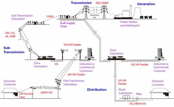
Figure 1. Basic Structure of Electric System[8]
Figure 1 shows the basic structure of an electric grid and where each of the three components are in the system. Power distribution and transmission make up most of the electric grid. These are possible using substations which act as nodes for different voltage levels. These nodes are connected to transmission lines and form the whole electric network.
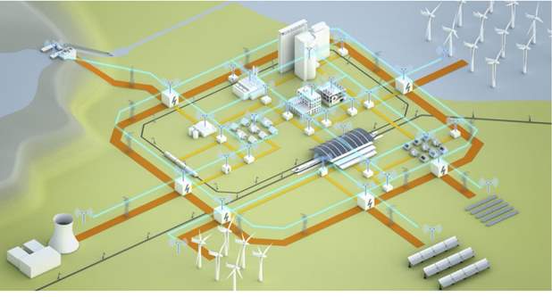
Figure 2. A Smart Grid (Siemens Energy Sector, 2014, p. 6)
A Smart grid is the next logical step-up from the traditional power grid; enabled by advances in technology and composed of ‘smart’ components such as smart meters and intelligent reclosers; the Smart grid promises improvements in efficiency, power quality as well as the integration of upcoming renewable power generation and storage elements as seen in Figure 2. Smart grids as opposed to traditional power grids are bidirectional in terms of the incorporation of data alongside power in the lines, thus opening the possibility of two-way communication between control systems at power stations/substations and street/local level smart components such as intelligent reclosers and smart meters. In a smart grid, power transmission and distribution is made automatic.
Intelligent power transmission is primarily implemented at substations. Various primary and secondary equipment is required, as well as a monitoring system in order to implement intelligent power transmission.
- Primary equipment – used directly for the production and transmission of electrical energy. Includes generators, transformers, high voltage wires and various switched along the line.
- Secondary equipment – refers to the equipment used for monitoring, measurement, control, and the adjustment of auxiliary equipment. Includes the meters, monitoring devices, and relay protection devices.
The ‘intelligence’ of intelligent power transmission is mainly reflected in the real-time status checking of equipment, panoramic monitoring, diagnostic evaluation, one-button sequence operation, automatic fault handling, intelligent inspection, auxiliary decision making etc. If all substations in a regional grid have implemented this system, the grid is likely to emerge as a major global innovation.
Intelligent distribution is for serving both the grid practitioners and the end users. It is mainly implemented through some mechanism to make power generation and distribution more automatic. Through this mechanism end users would be able to participate in the coordination and optimisation of distributed network resources.
| Compare | Traditional Grid | Smart Grid |
| User participate | Almost none. Only expected to pay the bill. | The user will be an integral part of the power system. Encourages and promote s the user to participate in their own operation and management. |
| Smart device | None | Two-way communication. Smart device will bring their own WIFI. The user’s electricity information will be sent to the power supply company network data terminal. Power supply companies will classify this data, do comparative analysis, and then according to the actual situation of the user, an electricity program will be tailored to them. Users can see the actual percentage energy usage of all devices in their home |
| Improve measure efficiency
and accuracy |
Uses mechanical meter, not
accurate |
In the smart grid, mechanical meter will be replaced by smart meters, and the collection interval will be significantly reduced. This accurate measurement will greatly improve the reliability of the grid, also can effectively carry out fault prediction and quick adjustment. |
| Self-prediction self-healing and self-regulation | None | Technical person can observe the whole network including power flow, power load hot zones, equipment, high-risk areas and customer focus area and other data to achieve a more intelligent grid. Features include:
|
| Improverenewable
resource use |
Our traditional power source is generally coal. Photovoltaic power generation, and wind power are difficult to connect withthe traditional power grid. | Smart grid simplifies the process of implementing new energy generation into the grid. Improved interconnection and standards will make a variety of power generation and energy storage systems easily accessible. |
| Energy storage technology, electric vehicles | In the past, the electricity produced must be used immediately, it was difficult to achieve large-capacity storage. | Whether it is a centralized large-capacity energy storage power plant, or distributed small-capacity energy storage power station, or even a vehicle battery, it will be used in smart grid. |
Table 1. Differences between traditional grids and smart grids
Section Two: Smart Meter
Smart Meter Function & Data Usage
Smart meters are meters implemented into smart grids which can collect large amounts of different types of information not previously possible with older meters. They allow for two way communication which means that it is possible to control the type of data that is obtained depending on the circumstance from a remote location. Hence, they also allow for the remote monitoring and control of various points in power systems. Points where smart meters can be used include feeders, substations and end points.
Depending on where a smart meter is installed it can be used for various purposes and collect data on various important electric parameters. The various uses for a smart meter can include:
- Monitoring and improvement of power quality
- Detection of power loss across the system
- Increasing efficiency of system
- Automated billing of customers
- Load control of off-peak devices and appliances
There are two typical types of smart meters that are used in conjunction in existing set-ups. Home Smart Meters and Overhead/Pole-top/Section Smart Meters or PMUs (Phasor Measurement Units)
Individual Home Smart Meters
- Transmit energy usage data to the utility, so that meter readers are no longer required
- Receive and carry out commands such as disconnecting the supply when customers move out and reconnecting it when the next customer moves in
- Monitor the supply for faults and automatically advise the utility in case of problems
- Can act as a two-way interface with the customer’s own appliances via a ‘home energy network’.
Section Smart Meters/PMUs/RTU (Remote Terminal Units)
- Load profile variations: Seasonal, Time, Customer Type (Industrial, Residential)
- Voltage Profile: Frequency, 3-phase Voltage and Current Waveforms, Transients
- Power quality: Power factor, Volt-VAR control, Fault Incidents, Voltage Regulation, Harmonic Content and Distortion.
- Fault Characterisation: Peak Fault Current and time.
Critical information at the time of fault incidents can also be collected, which will allow engineers and utilities to more easily determine possible causes of faults and formulate solutions and preventative measures. This results in reduced down time in the affected area and overall higher reliability of the system now and the in the long run.
Through the analysis of all the data collected, if it is found that there is incomplete data or abnormal values, then appropriate measures can be taken. These measures can include automatic repair, removal of restrictions on certain data, and an alarm for event data.
Using the data collected various forms of analysis can be applied to it in order to acquire the information required. Some possibilities are:
- Statistical analysis of power quality data such as the power factor, current, harmonics, voltage.
- Calculate the line losses, bus imbalance.
- Categorise and sort the data by various categories such as time periods, different locations, applications whether residential or industrial, power and load profile classification.
With two way communication being possible in a “smart grid”. This allows important information such as peak and off-peak onset and rates as well as rate of power consumption and the identification of high power consuming devices to be communicated to the customer. With this information, customers are then able to make informed decisions on power usage. Some of the existing examples of this are of the options for customers of Origin Energy in Victoria to request their interval data which “helps to populate information into your home profile that’s accessible when you log in online, as it provides an accurate reading of how much energy you’re using in what areas of your home.” [21].
This can result in overall lower peak demand which would lead to an increase in the ability of the network to supply power to everybody. There is also a reduction in the need for expensive infrastructure to provide the necessary capacity and support for peak demand periods which themselves occur infrequently.
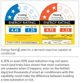
Fig 8. Savings and Benefits of Smart Meter and Demand Responsive Appliance Control, yourhome.gov.au
Smart Meter Communication | Common Section used between Group Members
An example of the types of communication systems used for Smart Meters are the ones currently used in Victoria’s state wide rollout of Smart Meters.
The two communication systems used in particular are:
- GridNet
- Silver Springs Network (SSN)
GridNet uses the Worldwide Interoperability for Microwave Access (WiMAX) protocol for its communication. WiMAX is based on the IEEE 802.16 standard and is an internet protocol (IP) based peer to peer (P2P) wireless protocol.
| GridNet (WiMAX) | SSN (Custom 900Mhz Protocol) |
| Allows multiple devices to communicate with a broadcast tower at a time. | Has no defined standard and is custom designed. |
| Requires a number of infrastructure, software and equipment elements to be set-up. Such as Towers, Fibre Optic cables, Network Management Software and back-up power supplies. | Offers better penetration through walls and buildings but has shorter range. |
| Requires communication to be routed through broadcast towers. | Utilizes P2P communication allowing meters to bounce messages off other devices. |
| Affected by factors such as antenna specifications, terrain, topography, environment and local conditions. | No singular network path for communication thus increasing the robustness of the network and resilience to fault conditions. |
| Supports higher data transfer rates in the mbps range. | Data transfer rates limited to between 10 and 250 kbps and more realistically at 20kbps. |
Smart meters produce large amounts of data so to attempt to avoid the big data issues caused by the constant transfer of information, Centralized control centres collects data from the smart meter through predominantly two methods known as:
- periodic polling
- triggered access
Periodic polling involves the smart meter being queried and sending a package of information of pre-set size and content to centralized control at intervals during the day. These intervals are usually set to four to six hours to avoid attempt to alleviate big data issues. An example of periodic polling would be for the smart meter rollout in Victoria where some “8 million records a day” [20] are being collected and managed. This data which is passed through a data management system can then be transferred to AEMO and power utilities which can analyze and make use of the information.
On the other hand, triggered access is used when abnormal system conditions are detected. The smart meters at specific locations along the grid start acquiring data related to the abnormal system condition or fault and send it to the centralized control structure. An example of abnormal system conditions could be voltage or frequency values exceeding limits set by Australian and Utility standards such as AS 60038. In this case, the information is sent to the centralized control structure which then takes actions to restore parameters to values within the thresholds.
Although smart meters provide a much larger amount of information on the network, this also means that it is much harder to store all of the information. This represents a “big data” challenge that is covered later on this report and in future work.
Section Three: Intelligent Recloser
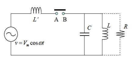 A circuit breaker is a protective device that can be scaled up or down in terms of current rating and size for use from power distribution grids to protection of households and low voltage sensitive electronics. An equivalent circuit diagram of the traditional circuit breaker can be seen below in figure 9.
Figure 9. Circuit Breaker Equivalent Circuit Diagram.
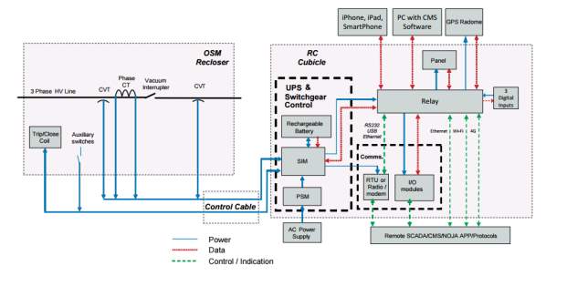 A recloser is an advancement of the circuit breaker in that after tripping and interrupting faults and transient surges it can (via electromechanical or electronic control) be reset remotely to restore power to sections of the grid. Thus, it reduces grid downtime and costs spent in manually resetting circuit breakers and the investigation of faults that resolve themselves. The advancements and integration of electronics and microsystems into the traditional circuit breaker can be seen in the schematic of the Noja Power OSM recloser and control system is shown below in figure 10.
Fig 10. Noja Power Recloser and Control Cubicle Breakdown.
These are some of the standard characteristics of Intelligent Reclosers (NOJA Power, 2011):
- Rated for the medium voltage range of 10-38kV
- Robust in enough in construction and structure to be able to “resist vibration, temperature extremes and inclement weather” that transmission poles are commonly subject to.
- Relatively lightweight, approx. 100kg
- Supports functions such as remote control/communication, data and event logging and interfacing with smart meters. Achieved primarily by digital/microprocessor electronics and communication protocols.
Possible functions of the intelligent recloser range from fault isolation and detection, automated circuit closing to re-establish grid power and utilization in rerouting and sourcing power from distributed sources in the grid to cover shortfalls/sections.
By utilizing the two-way communication channels introduced by a smart grid, utility companies can communicate/control not only higher level functions but local consumer level smart elements.
In this case, smart elements such as intelligent reclosers can significantly improve power quality in general as well as respond to the increasing penetration of renewable and distributed energy sources in the modern power grid.
Comparison between the Intelligent Recloser and Traditional Circuit Breaker
| Traditional Circuit Breakers | Intelligent Reclosers |
|
|
|
|
|
|
|
|
Examples of Intelligent Reclosers and their Communication Capabilities
 Noja Power OSM Recloser:
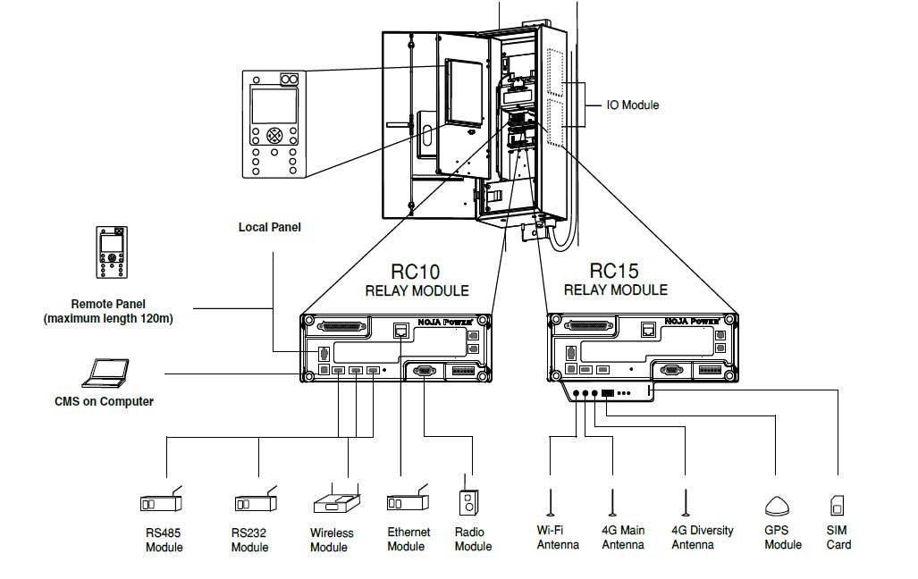 Figure 3. Noja Power OSM Recloser
Fig 12. All the various communication methods available with the Noja Power Recloser and Controller.
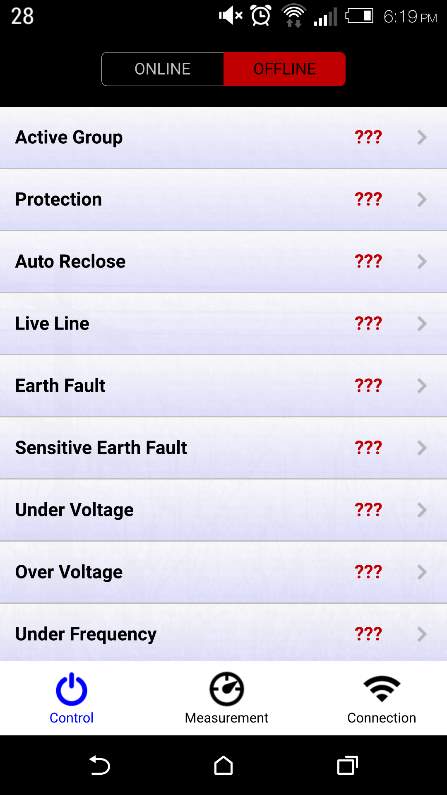
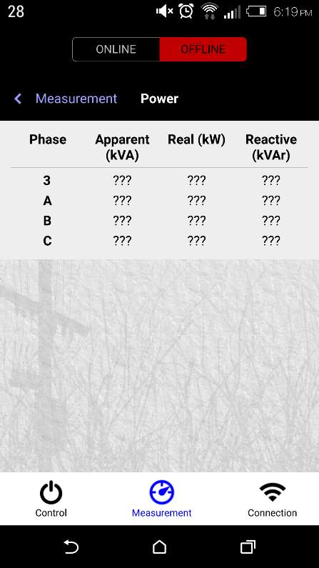
On-top of all the communication methods shown in figure 12, there is also the NOJA Power Recloser App which is a communication capability designed to work with their RC10 recloser controller and thus enables you to diagnose and control NOJA RC10 based reclosers remotely [9]. The recloser app is designed for operators and line crews to interface with their pole mounted reclosers and thus avoid some of the safety hazards associated with high voltages and heights.
The smartphone app showcases features such as measurement capabilities for a wide range of physical and voltage profile based attributes as well as a number of options to control the recloser. Connecting to different reclosers in the area simply requires the recloser’s fixed IP address and a Wi-Fi connection making it very simple. Overall the application is used as an alternative to SCADA and centralized control systems but still allows for line crews to diagnose faults and receive information about reclosers.
For pictures of the smartphone app; which is free to download; refer to appendix A.
 Intellirupter Pulse Closer Fault Interrupter:
Figure 3. Intellirupter Intelligent Fault Recloser
S&C’s Intellirupter Fault Interrupter shown in figure 3 works off a Wi-Fi connection and has a wide array of integrated controls and current/voltage sensing and data acquisition.
It also features their proprietary fault recovery software/system known as “SG Automatic Restoration System” which is scalable and utilizes peer to peer communication and their reclosers to restore service and isolate faults. It is compatible with any alternate sources and thus able to use wind, solar and even battery power storage elements to restore power to fault unaffected sections of the distribution network.
It can be used without SCADA however it fully supports integration with SCADA and can therefore be remotely controlled at a centralized control point.
Some of the additional communication features include [12]:
“Bracket-mounted antenna. Extends 4 feet from the base; attaches at either end. Includes 900-MHz, 3-dBd-gain, omni-directional antenna, or 900-MHz, 9-dBd gain, directional Yagi antenna.”
“Wi-Fi tester. Simulates a connection to the communication module. Confirms your laptop computer can establish a secure Wi-Fi connection to your Intellirupter fault interrupter.”
Communication Protocols
For proper peer to peer communication between smart elements such as Intelligent Reclosers and Smart Meters, there needs to be support for standardized communication protocols. Some examples of such communication protocols are:
DNP3:
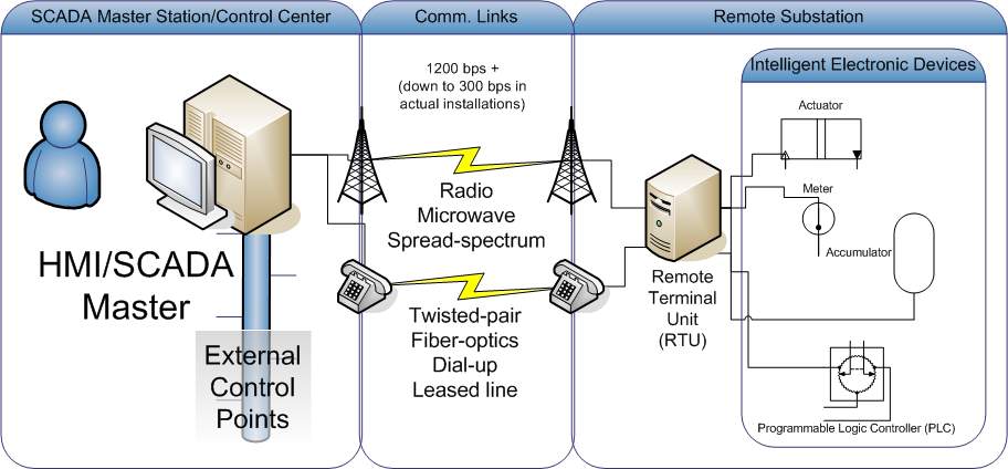 Is a communication protocol used in industry and automation systems and is used extensively in SCADA systems comprising of Intelligent Electronic Devices for smart grid applications. DNP3 trades off being complex to be able to be extremely robust and reliable even in the face of common communication issues such as EMI interference and poor transmission media.
Figure7. Example of the DNP3 communication in a system with SCADA and IEDs. [14]
MODBUS:
Much older communication protocol that was created by Schneider Electric and has been the industry standard historically due to easy of deployment and maintenance, open licensing and publication such that usage is loyalty free and that it had been developed specifically for industrial applications.
IEC 61850:
Developed as a standard compatible with products from any vendor and made specifically for IED devices; so that they are able to communicate peer to peer and make possible some basic functions of a smart grid; it is a protocol that can be used over TCP/IP and LAN networks making it readily compatible with communication methods such as Wi-Fi.
A different communication protocol which allows for communication between smart meters and intelligent reclosers is the IEC 61850 protocol. It is an Ethernet-based communication standard. It incorporates the Generic Object Oriented Substation Events (GOOSE) protection-speed messaging protocol. This means that it allows for high-speed protection, transfer switching, fault isolation and service restoration. Due to the high speed of this protocol it allows for quick identification and isolation of the fault in order to quickly solve it.
Section Four: Power Quality
Power quality refers to the quality of the AC power supplied to the client through the grid. Traditionally the emphasis has been on delivering a clean and stable power supply from the power plant/supplier to consumer. Some of the factors that affect power quality and therefore need to be controlled and monitored are listed [1]:
- Voltage Regulation/Load Variations/Flicker
- Voltage Sags and Swells
- Harmonic Content
- Real and Reactive Power
- Voltage and Current Transients
- Fault Incidence
Overview of Relevant Local and International Power Quality Standards
AS 60038—2012 (Voltage Regulation)
AS/NZS 61000.4.30:2012 (Power Quality testing & measurement)
IEEE Standard 519-2014 (Harmonic Content Control)
TR IEC 61000.3.6:2012 (Electromagnetic compatibility (EMC) Limits – Assessment of emission limits for the connection of distorting installations to MV, HV and EHV power systems)
On top of this, with the increasing rate of penetration of renewable and distributed sources in the modern power grid it is harder to maintain power quality. Proper integration and control of these sources is becoming of paramount importance to power quality and this has contributed to the growing interest and research into smart grids.
Some of the main issues to do with the integration of renewable and distributed sources into the power grid include:
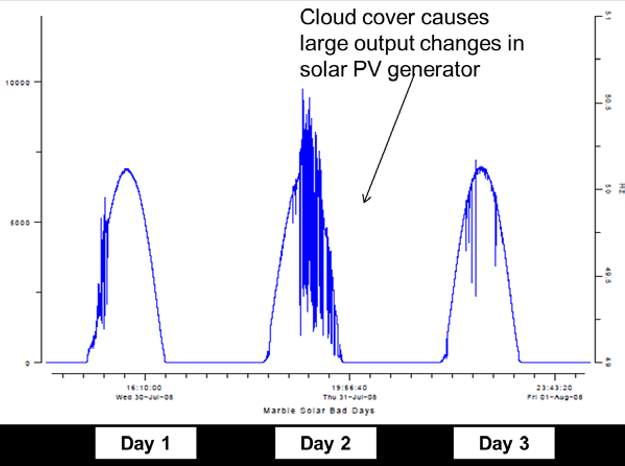
- The volatility of power supply: When concerned with renewable sources such as Wind and PV whose output can vary depending on weather conditions and time of the day/year.
With respect to PV systems, “the output power of a large solar PV system with rating of tens of megawatts can be change by 70% in five to ten minutes of time frame by local phenomenon like clouds passing”. Additional complexity involved in PV controllers for combining sunlight tracking, MPPT (maximum power point tracking) and storage options also contributes to integration difficulties.
- Introduction of voltage fluctuations and noise, this is evident in that “wind turbines are among the utilities considered to be potential sources of bad power quality” [1] due to their generation of harmonic distortion in the output and their contribution to voltage flicker.
Solutions and Findings
FLISR/FDIR (Fault Location Isolation Supply Restoration)/(Fault Detection Isolation Restoration)
Definition of the Self-healing Process/FLISR Operation
FLISR stands for Fault Location Isolation and Supply Restoration and is a process/system by which utilities can recover from faults on a distribution network and engage in troubleshooting without needing to rely on conventional grid practices.
With the introduction of IED (Intelligent Electronic Devices) such as smart meters and intelligent reclosers, utility companies no longer need to spend large amounts of capital on achieving visibility of their distribution network or resort to sending operators to possibly dangerous situations to restore service.
The FLISR process includes the following steps/applications [13]:
- Fault Location: Locating the part of the feeder with the faulted network element (e.g. faulted cable or overhead section) using appropriate methods. These methods take into account all deployed equipment in the distribution system for fault detection and location.
- Fault Localization: Locating the part of the feeder with the faulted element using remotely and/or manually controlled switching devices.
- Element (Fault) Isolation: This step isolates the faulted element from the remaining part of the feeder.
- Service Restoration: Re-supplying of de-energized sections on the faulted feeder via switch orders.
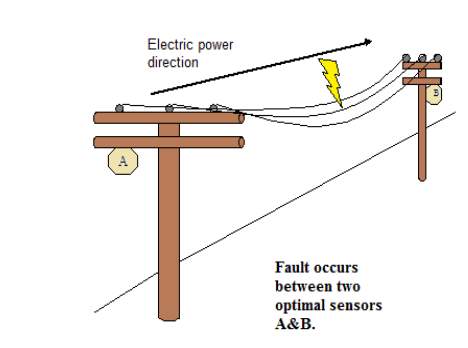
Figure 3. Fault Incident between two IED sensors on overhead lines. [3]
Illustration and Breakdown of the FLISR Process
Previous reports have explored the role of Intelligent Reclosers in a Smart Grid and how they can operate in concert with other IEDs in an electrical distribution network to isolate faults and comprise what is known as a “self-healing system”/FLISR system.
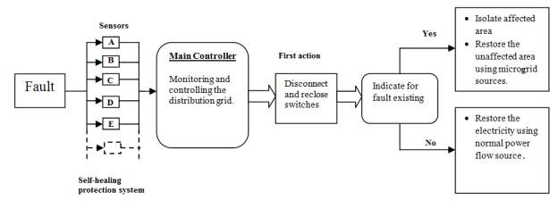
Figure 5: Self-healing Protection Network Block Diagram. [3]
The picture shown in Figure 5 illustrates the process by which street/section level intelligent reclosers with two-way communication between higher level controllers are able to isolate fault incident areas based on sensor information from smart elements and utilize or integrate micro-grid sources such as renewable or distributed sources. This integration of other sources and isolation of faults for troubleshooting allows for high power quality and stability to be maintained despite faults, and demonstrates the basic process for a self-healing system in upcoming smart grids.
A previously explored but important example of intelligent reclosers improving power quality would be in the case of fault currents caused by incident lightning on a local consumer level.
The main source of external impulse/fault generation is lightning activity whether by direct strike to a line or by EMI coupling due to a strike in the proximity. Lightning strikes are transient faults and thus in most cases after tripping, a recloser can re-establish power after the fault resolves itself unlike circuit breakers at substations/feeder stations that often require manual resetting.
In the case of a fault current caused by a lightning strike on the line, the recloser can isolate the location of the fault and inform the operator or automated control systems. Other featured of modern reclosers are their ability to store information on the time of the fault as well as the local electricity usage patterns. This allows for engineers to analyse the information and possibly find a reason for why the fault occurred, whether it be due to external sources such as lightning or by surges in demand caused by inductive loads such as transformers or motors.
Figure 6 shows how an incident fault is handled by a FLISR system comprising of sectionalizing and substation reclosers. In this figure, a fault occurs in the middle of a distribution network and with communication via smart recloser elements on actual fault location, the FLISR system is able to isolate the fault and re-establish service for customers outside of the fault section.
A FLISR system that uses intelligent reclosers requires a network wide communication systems and will need to be able to communicate via standardized communication protocols in order to perform its function. This requires the implementation of a SCADA (Supervisory Control and Data Acquisition) system comprised of “computers and networked data communications” as well as intelligent hardware elements (smart meter, intelligent recloser) that allows utility companies and line crews to be able to visualize and control various elements of their smart grid.
These elements range from self-healing to voltage and load profiles, distributed sources, volt/VAR control and even power factor correction.
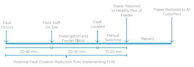 This can lead to a large reductions in the time taken for utilities and line teams to debug sections of the feeder line and affect repairs which has additional benefits in reducing the number of complaints and queries as to the status of the line by customers. As a whole, savings in service/call centre upkeep and a reduction of the costs spent on having technicians and teams on standby throughout the day and all the necessary equipment and overhead spent on such tasks.
Fig 18. Reductions in fault duration due to implementation of FLISR/FDIR. [21]
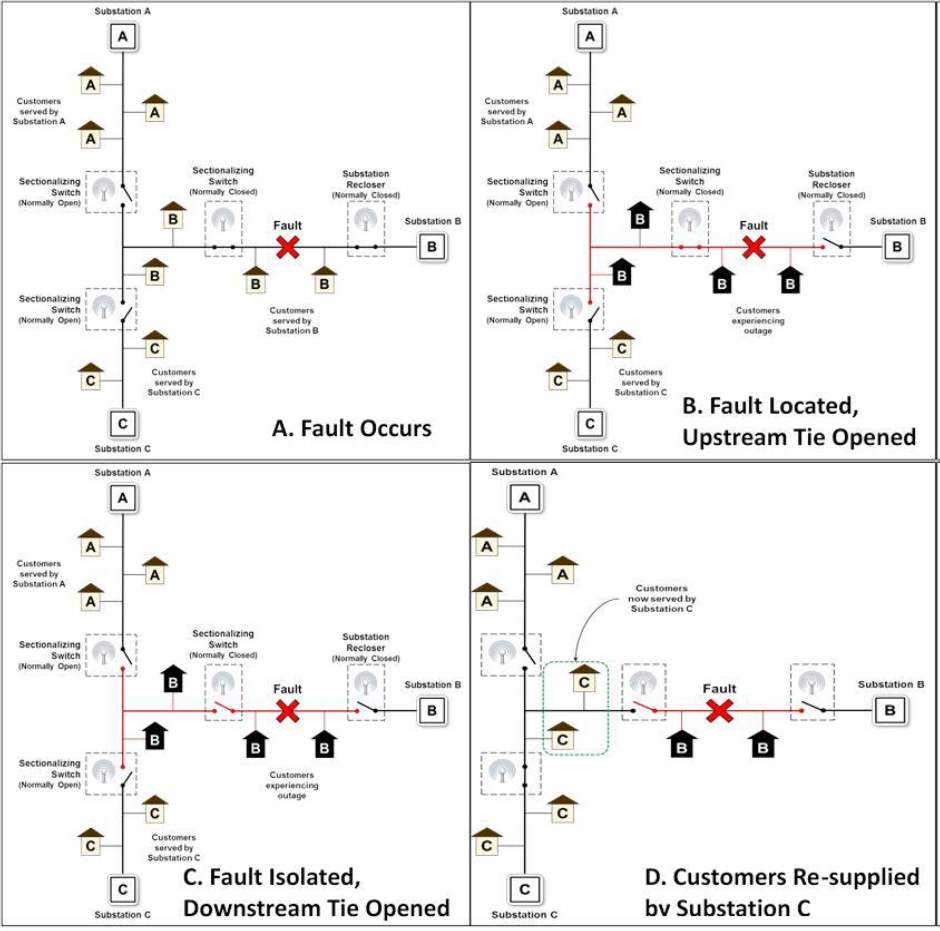 Figure 6. Schematics Illustrating FLISR/Self-healing Operations. [10]
Communication Infrastructure
Most crucial to deploying and maintaining a SCADA based FLISR system is the utilities communication infrastructure. It is crucial due to the need for robust communication between peers and substations. This is a result of several factors such as the increasing adoption and demand for smart grid implementation and installations worldwide, increasing shift away from conventional sources towards distributed and renewable energy sources, increasing EMI pollution and distortion and the increasing amounts of data being produced by IED elements.
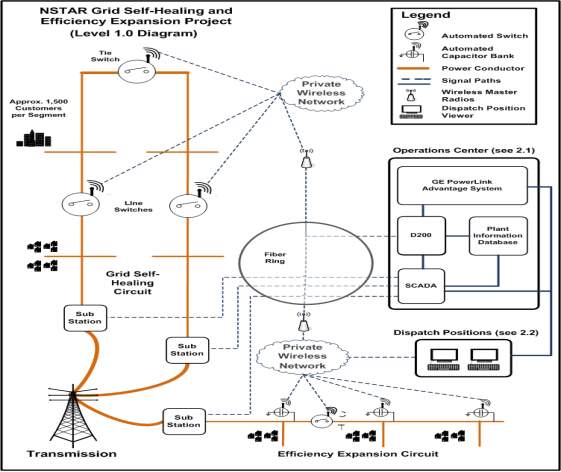
Figure 8. Schematic of Communications Architecture at NSTAR. [10]
In the above Figure 8, the existing communication infrastructure/architecture of the American utility company NSTAR is shown to be comprised of smart recloser elements connected to VPN’s which are subsequently connected to a fibre optic ring to NSTAR’s SCADA and centralized control location.
However as evaluated by the US Department of Energy, NSTAR’s communication infrastructure was insufficiently robust and had “lacked radio coverage to accomplish required tasks” [10].
Alongside this, the US DOE proposed a number of “lessons learned” that utility companies need to be aware of when integrating FLISR systems into their existing communication infrastructure.
- “Automated devices often require more frequent firmware and software upgrades— as well as customized refinements to meet the unique needs of various distribution system configurations.” [10].
- “Utilities with legacy communication networks should conduct evaluations and implement upgrades before deploying FLISR technologies and systems” [10].
- “The utilities found that communication networks require greater resilience than power delivery systems because they must be able to control automated switches under conditions where the grid system is damaged or not functioning properly due to downed lines, faults, or other grid disturbances.” [2]. Problems with traditional Radio communications due to EMI interference, prompting the use of twisted pair, Wi-Fi and fibre optics.
Another case where intelligent reclosers play a role in upholding power quality is related to load profiles, load factor, peak demand and compensating for the volatility of renewable/distributed sources with respect to fluctuations in voltage, reactive/active power.
When there are extended periods of voltage instability or fluctuations due to changes in load profiles or faults, intelligent reclosers can allow grid operators to remotely communicate with affected areas and control the supply of mains power via spinning reserves and non-spinning reserves in order to cover shortfalls in supply caused by renewables sources or abrupt increases in load demand. [4]
Another notable example of the streamlining of troubleshooting and increased information resolution afforded by intelligent reclosers includes the ability to control and analyse the information stored through smartphone applications and Wi-Fi connectivity. With this information, local technicians can perform troubleshooting and identify possible detriments to power quality.
Existing Set-ups and Implementations
Active Volt-VAR Control and Power Factor Control
 AVVC (Active Volt-VAR Control) and PFC (Power Factor Control) is the means by which utilities can monitor the voltage and current at various locations on the grid in real-time, and to use this information to control the distributed voltage and reactive power that is supplied to the grid and customers through software and algorithm based control.
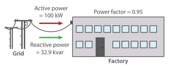
- Nearly all power system loads require a combination of real power (watts) and reactive power (VARs). Real power must be supplied by a remote generator while reactive power can be supplied either by a remote generator or a local VAR supply, such as a capacitor.
- Delivery of reactive power from a remote VAR supply results in additional feeder voltage drop and losses due to increased current flow.
- VAR supply on a distribution feeder is regulated or controlled by switching capacitors on during periods of high demand and off during periods of low demand.
- The ability to optimize a power factor means that the utility has to generate less power to satisfy the demand of its customers.
- In simple terms, certain power factor conditions require utilities to generate more real power than is actually needed by its consumers. This excess real power is wasted in the form of thermal losses. The ability to optimize power factor is a key driver in a utility’s ability to minimize losses.
- This particular benefit also serves the environment; if a utility has to generate less power to serve the same demand then in turn they burn less coal or natural gas and therefore emit less CO2.
How Active Volt/VAR Optimization Improves Grid Efficiency [22].
Power Distribution networks are designed and built in order to provide stable and clean supply all year round to all current and prospective customers. Therefore additional investments and infrastructure must be made to meet and accommodate expected peak demand.
Network voltage, which can move up and down in response to load fluctuations, needs to be controlled to ensure it remains within +10/-6% of 230V as specified by Australian standards1. To minimise electrical losses in the network caused by electrical resistance, and ensure that the network assets are used optimally, the power factor should be maintained as close to the optimum level (unity) as possible.
Network providers currently control network voltage and reactive power via Volt-VAr control devices such as switched capacitor banks and tap-changing transformers. These rely on localised measurement of voltage and current to determine the control actions of the device. They have a simple control objective (for example, keep local voltage within a pre-determined range), and operate independently of other similar devices deployed at other points in the network.
This static approach limits the ability of the network provider to quickly respond to changes in the network state and results in suboptimal system configurations outside of peak times. The increasing number of distributed energy resources in Australia, predominantly solar PV, mean that the network state is becoming increasingly dynamic and can create new voltage issues for the network provider to manage.
The main benefits of implementing AVVC as part of a smart grid could be expected to include:
- Deferring capital expenditure and reducing emissions by reducing voltage at peak and optimising the power factor
- Reducing losses, energy consumption and emissions by increasing voltage all other times
- Improving power quality by providing an integrated response
Peak demand and energy consumption are reduced through conservation voltage reduction (CVR), which involves operating tap changers in transformers to reduce feeder voltage, which in turn reduces customer’s energy consumption. This relationship, known as the CVR factor, is proportional, i.e. a 1% reduction in feeder voltage results in an equal reduction in energy consumption.
Utilising capacitor banks to compensate for reactive power caused by inductive loads (e.g. motors) results in a flatter voltage profile along the feeder, in turn reducing electricity losses.
With multiple monitoring and control points throughout the network, AVVC enables the network provider to implement complex control functions and adapt to changing feeder configurations, load conditions and varying operational requirements to improve power quality. This also means that it can better manage and control the dynamic effects of increased distributed generation.
Integration of Renewable/Distributed Sources and Storage
On the contrary “peak network demand occurs less than 1% of the year” [23], this means that a large proportion of the capital spent on such infrastructure and investments is heavily underutilized.
This desire to reduce peak demand is tied to the function of “peaker power plants” and the surrounding infrastructure which is used to accommodate the “peak” network demand that can occur during peak periods as well as aforementioned network peak demands which occur very infrequently.
Therefore an ongoing field of research and adoption is the use of distributed storage and sources such as battery storage. The numerous benefits of batteries as distributed storage as compared to building entire “peaker power plants” can be seen in figure 19.
These include the absence of significant standby/overhead costs, immense reduction in pollution and greenhouse emissions, flexibility and responsiveness of dispatch and supply, the stark difference in the periods when they service the grid and the capability for batteries to act as loads and charge themselves depending on grid conditions due to their flexible range.
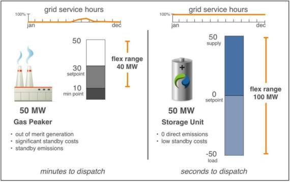
Fig 19. Comparison of Peaker Power Plants and Battery Storage for accommodating peak network demand.
“There are usually peaker plants idling for occasions like this and they can usually ramp up in 3 to 5 minutes. Then you kick on the other plants and that can take up to 20 minutes. You are burning a lot of fossil fuels to keep this system going. That is an area where batteries are superior.They are available in a millisecond, or as fast as the inverter can switch.” [24]
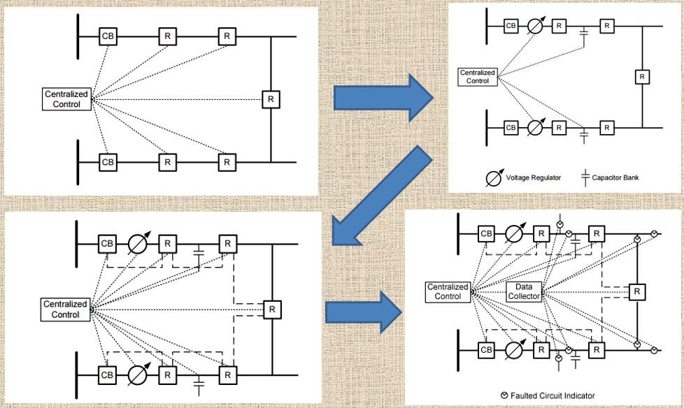 Figure 9. Progression toward more advanced and ideal FLISR/Distribution Control systems. [11]
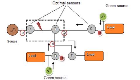
Figure 4. After fault isolation and in a smart grid with distributed renewable sources. [3]
Another function by which intelligent reclosers can maintain power quality and minimize interruptions in service due to faults is by the rerouting power sections around the fault and incorporating distributed renewable sources in the grid to cover shortfalls in supply. Figure 4 shows the incident of a fault current between points A and B and the use of reclosers surrounding the points to isolate the section from the power grid while utilizing “green sources” or otherwise renewable energy sources in the grid to supply loads while the fault is being cleared.
Barriers and Challenges to Implementation
In addition to the need for a robust communication infrastructure, the topology of how the IED elements in a smart-grid distribution system communicate and subsequently how FLISR and other control systems are implemented is also extremely important.
A number of topologies for creating a self-healing smart-grid distribution network is shown below in Figure 9.
It showcases initially a centrally controlled network for automation which progresses to include voltage regulation and power factor correction features/elements. As it progresses, it gets more advanced, featuring peer to peer communication for high speed protection and redundancy and in the last picture, shows the addition of data collection/filtering capabilities to deal with the large amounts of data that results from the real-time data logging of smart-grid IEDs.
Conclusion
thfthtfghfthth
Future Work and Direction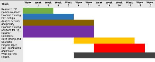
Figure #. Gantt chart timeline for Thesis B Work.
Reference List
[1]V. Kumar, A. Pandey and S. Sinha, “Grid Integration and Power Quality Issues of Wind and Solar Energy System: A Review”, International Conference on Emerging Trends in Electrical, Electronics and Sustainable Energy Systems, vol. 16, pp. 72-80, 2016.
[2]”NOJA Power Recloser App”, Play.google.com, 2017. [Online]. Available: https://play.google.com/store/apps/details?id=com.nojapower.recloser&hl=en. [Accessed: 02- Apr- 2017].
[3]M. Aljahani, “An Enhanced Self-Healing Protection System in Smart Grid: Using Advanced and Intelligent Devices and Applying Hierarchical Routing in Sensor Network Technique”, Masters, Western Michigan University, 2014.
[4]A. M G, P. P and D. inesh, “Renewable Energy Integration into Smart grid: Problems and Solutions Based on Indian Power Scenario”, International Journal of Scientific & Engineering Research, vol. 6, no. 4, pp. 1066-1067, 2015.
[5]Hiesik Kim, Odgerel Ayurzana. Improvement of data receive ratio in remote water meter system by upgrading sensor[J]. International Journal of Control, Automation and Systems, 2009, 7(1):145~150.
[6]Elster, “Realising the smart grid of the future through AMI technology”, Available: https://www.elstersolutions.com/en/realizing-the-smart-grid-of-the-future-through-ami-technology.[Accessed: 17- Mar- 2017], 2016.
[7]N. Browne, T.J. Browne, S.T. Elphick, “Monitoring Intelligent Distribution Power Systems: a Power Quality Plan”, 14th International Conference on Harmonics and Quality of Power ICHQP 2010, 2010, pp. 1-7.
[8]”NSW HSC physics syllabus”, available: http://australiancurriculumphysics.com.au/fathoming-physics-hsc-textbook/ , 2015
[9]”NOJA Power Recloser”, Play.google.com, 2017. [Online]. Available: https://play.google.com/store/apps/details?id=com.nojapower.recloser&hl=en. [Accessed: 21- Apr- 2017].
[10]U.S. Department of Energy, “Fault Location, Isolation, and Service Restoration Technologies Reduce Outage Impact and Duration”, U.S. Department of Energy, 2014.
[11]B. Glennon, C. Kusch and E. Nelson, “Improve Reliability and Power Quality on Any System”, Schweitzer Engineering Laboratories Inc, 2012.
[12]”IntelliRupter® PulseCloser® Fault Interrupter”, Sandc.com, 2017. [Online]. Available: https://www.sandc.com/en/products–services/products/intellirupter-pulsecloser-fault-interrupter/#Product Details. [Accessed: 21- Apr- 2017].
[13]”Fault Location Isolation & Supply Restoration (FLISR) | Schneider Electric”, Schneider-electric.us, 2017. [Online]. Available: http://www.schneider-electric.us/en/work/solutions/for-business/s4/electric-utilities-fault-location-isolation-and-supply-restoration-flisr/. [Accessed: 21- Apr- 2017].
[14]”DNP3″, En.wikipedia.org, 2017. [Online]. Available: https://en.wikipedia.org/wiki/DNP3. [Accessed: 21- Apr- 2017].
[15]”Department of Economic Development, Jobs, Transport and Resources, Victoria, Australia” Available: http://www.smartmeters.vic.gov.au/about-smart-meters/reports-and-consultations/advanced-metering-infrastructure-cost-benefit-analysis/3.-technology-deployed-in-victoria,2015
[16]Contributed By Digi-Key’s European Editors”Keeping the Smart Grid Smart” available:
https://www.digikey.com.au/en/articles/techzone/2013/nov/keeping-the-smart-grid-smart
[17] Sun parasitic. Research and application of 10kV ring network power supply technology [J]. China Electric Power, 1999,32 (2).
https://www.itnews.com.au/news/jemena-hooks-consumers-with-smart-meter-data-308957
https://www.originenergy.com.au/for-home/my-account/usage/how-to-read-my-bill/vic-smart-meter.html
NEMA Volt/VAR Optimization Improves Grid Efficiency
http://energypost.eu/battery-storage-will-take-backup-power-plants/
Appendices:
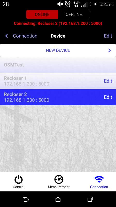
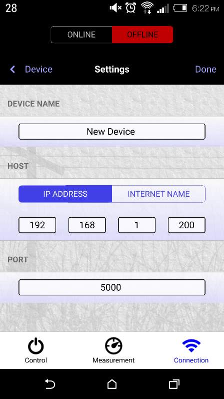
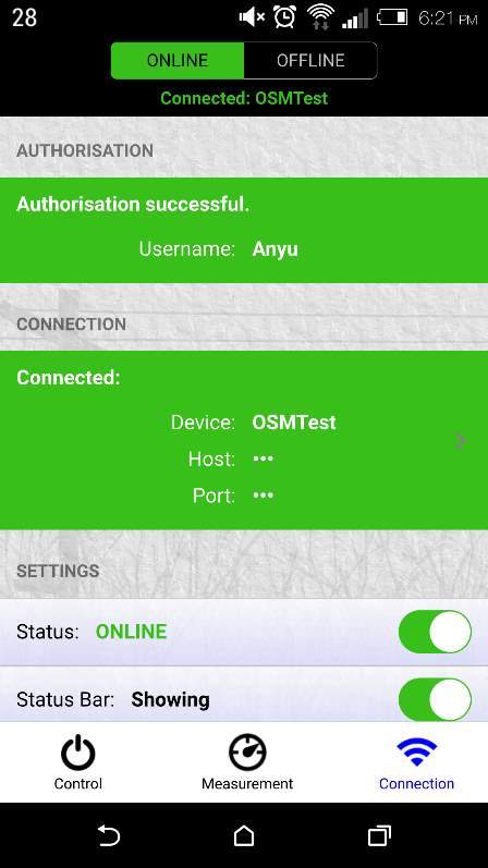
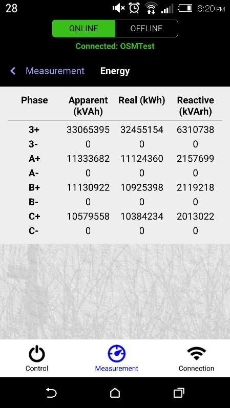 NOJA Power Recloser Smartphone App
Cite This Work
To export a reference to this article please select a referencing stye below:
Related Services
View all


Related Content
All TagsContent relating to: "Energy"
Energy regards the power derived from a fuel source such as electricity or gas that can do work such as provide light or heat. Energy sources can be non-renewable such as fossil fuels or nuclear, or renewable such as solar, wind, hydro or geothermal. Renewable energies are also known as green energy with reference to the environmental benefits they provide.
Related Articles

DMCA / Removal Request
If you are the original writer of this dissertation and no longer wish to have your work published on the UKDiss.com website then please: