A Smart Localization System with Hybrid Information Collection
Info: 9353 words (37 pages) Dissertation
Published: 11th Dec 2019
Table of Contents
2.1 Advantages of a Wireless Sensor Network
2.2 Applications of a Wireless Sensor Network
2.3 Adhoc Network Vs. Wireless Sensor Network
4. Topology of Wireless Sensor Networks
5.2 Imposing a Structure Architecture
6.1 Layering Based Security Approach
8.6 Testing MTS400 Capabilities
Table of Figures
Figure 1 A typical wireless sensor network
Figure 2 Typical Adhoc Network: Where the nodes act as routers
Figure 3 Using an OEM Sensor Node vs. Building Your Own
Figure 4 Sensor Node Architecture
Figure 5 Multi-hop Network Architecture
Figure 6 Star Network Topology
Figure 7 Mesh Network Topology
Figure 8 Cluster Tree Network Topology
Figure 10 Chain Based Data Gathering Using Directed Diffusion
Figure 15 MIB520 and XM2110 Combined to make a base station
Figure 16 Interfacing the Board
Figure 17 Configuring The Board as a Base Station
Figure 18 Checking Which COM Ports are Being Used
Figure 19 Uploading The Required HP File
Figure 20 Final Step in Configuring the MIB520
Figure 21 Mote Successfully Being Configured
Figure 23 Select the highest COM port for programming
Figure 24 Selecting the Compatible Sensor Board
Figure 25 Lower COM Port (COM3) must be chosen
Figure 26 MTS400 Sensor Bottom View
Figure 29 List of Nodes in Left Side Tab
Figure 30 Sensor Node’s Parameters
Figure 31 Regular Updates of Calibration
Figure 32 Voltage of Batteries Being Displayed
Figure 33 Humidity Data being Monitored
Figure 34 Surrounding Temperature being Monitored
Figure 35 Pressure Data being Displayed
Figure 36 Amount of Light Being Detected
Figure 37 Room’s Light being Displayed on the GUI
Figure 38 Displaying Total Darkness When Sensor is Covered
Tables
Table I Differences Between an Adhoc Network & a Wireless Sensor Network
Table II Comparison of the Different Sensors Offered by Memsic
Appendix
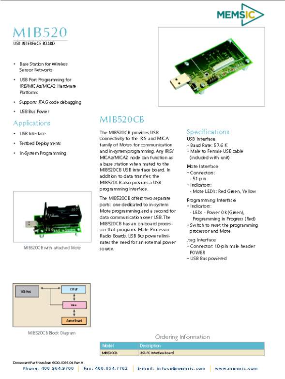 MIB520 Datasheet
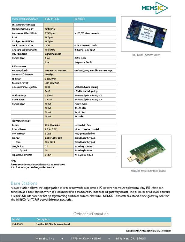
XM2110 Mote Datasheet

MTS400 Datasheet

1. Abstract
This project aims to develop a dedicated small and low-power consumption location estimation and tracking system based on wireless sensor network technology. Accurately locating and tracking individuals and objects in environments such as indoor or underground areas with metallic industrial installations cannot be achieved with GPS technology due to low penetration of high frequency GPS satellite signals through materials. Existing solutions for indoor location systems based on infrared, ultrasound and radio frequency technologies relies on extensive dedicated infrastructure and prohibitively expensive for mass scale applications. The proposed project will use a relatively small number of reconfigurable fixed nodes and the information from other mobile nodes in the neighborhood to estimate a location of a given mobile node. As all mobile nodes are full duplex transceivers they can exchange information about their own locations and, once a node’s location is estimated, it will then act as a “mobile beacon node” for other mobile nodes. Furthermore, the wireless sensor nodes used for location estimation can potentially collects information about the environment and transmits that to a central database. During the proof-of-concept project network simulation software and commercially off the shelf sensor platforms will be used to experimentally verify the performance of the proposed system. Typical applications of this system include, keeping track of personnel and equipment in oil refineries, underground piping installations and cleaning, monitoring residents with health concerns in residential aged-care facilities and providing assistance to customers in shopping malls and underground or multi-story car parking.
2. Introduction
Wireless sensor networks (WSN) are widely scattered self-sufficient sensors to observe physical or environmental conditions, such as temperature, sound, pressure, light, location, and
many others. By collecting this wide array of data; each sensor is able to communicate with each other and transmit their information back to the main base. Wireless sensor networks provide flexibility to aid in problem solving through a variety of real life applications, and implementing them in certain industries will change how they operate for the future of networking. This report will explore what a wireless sensor network is, the components, and the relevance of researching and implementing a WSN.
There are numerous applications a wireless sensor network may be able to perform in. One of the key benefits of wireless sensor networking is that the node is able to store power, whether in the form of batteries or external power supplies. This gives them a massive advantage in portability, and their robust build allows them to be used in harsh conditions. These abilities make wireless sensor networks ideal for monitoring situations. Some of important applications are environmental monitoring, traffic control applications, weather monitoring, and observing temperature. These are all dependent on the sensor board that each node is coupled with. The type of sensor that is used with a node effects the purpose of the network and what is being monitored.
Typically, a wireless sensor network contains hundreds of thousands of sensor nodes. The sensor nodes can communicate between themselves using radio signals. A wireless sensor node is equipped with sensing and computing devices, radio transceivers, and power components. One main component is the base station. A base station is an interface between the application platform (MoteView) and the wireless nodes on the wireless sensor network. All information received from the wireless nodes is gathered by the base station and forwarded to the application. Another component is the node. Nodes are usually called routers, and they are used to extend network coverage area, route around obstacles, and provide back-up routes in case of network overcrowding or device failure. The final component is the sensor. This is the device used for interaction with the physical system that is being monitored; such as temperature and light. (Cecílio 2016).
The individual nodes in a wireless sensor network are limited with their resource. The nodes have limited processing speed, bandwidth, and storage space. After the sensor nodes are positioned, they are responsible for creating a network structure such as a mesh or star design to communicate with each other. Then the sensors that are attached to each node start collecting information such as location and temperature. Wireless sensor devices also respond to requests sent from the base station to perform specific instructions or provide sensing samples. Global Positioning System (GPS) and local positioning algorithms can be used to obtain location and positioning information depending on the sensor coupled with the node.
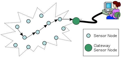
Figure 1 A typical wireless sensor network
Currently, majority of the research on WSNs has concentrated on the thermal design, improving the efficiency of calculating algorithms, and the application that controls the nodes and base station has been limited to simple data monitoring and reporting purposes. (Labrador et. al. 2009). WSNs are possible today due to technological advancement in various domains. Wireless sensor networks are seen to become an essential part of our lives. To further increase the likelihood of implementing in everyday life; design constraints need to be improved upon in the future. The purpose of this project is to design a wireless sensor network to be implemented with a fire fighting robot to aid in collecting relevant information in certain situations.
2. Literature Review
Global Positioning System (GPS) is a system of orbiting satellites that send precise details of their position in space back to earth. The signals are obtained by GPS receivers, such as navigation devices and are used to calculate the exact position, speed and time of a user’s location. This allows a GPS system to be used in a wide variety of applications that involve location tracking. Considering the wide use of a GPS; sometimes the GPS signals are not accurate due to some obstacles blocking the signals such as buildings, trees, and severe atmospheric conditions. To overcome these limitations proposed by a GPS; implementation of a wireless sensor network may be suggested.
Wireless sensor networks have been chosen because of their requirement for low device complexity coupled together with low energy consumption which enables a long lifetime for the device. Key characteristics of a WSN include power consumption constrictions for nodes using batteries, resilient when faced with failures, portability of nodes, the diversity of the nodes, has a very large of operation, very durable, and very simple to operate.
2.1 Advantages of a Wireless Sensor Network
- Network setups may be implemented without any certain layout.
- Can be used in difficult to access areas
- Flexibility to add more nodes if the situation calls for it.
- Cheap to implement.
- Significantly less wiring.
- May easily be accessed by a computer.
2.2 Applications of a Wireless Sensor Network
Wireless sensor networks have gained considerable popularity due to their flexibility in solving problems in different application domains and may be applied to certain industries to simplify many tasks.
- Military applications: Wireless sensor networks maybe an integral part of military command, control, communications, computing, intelligence, battlefield surveillance, reconnaissance and targeting systems.
- Area monitoring: In area monitoring, the sensor nodes are positioned over a region where some occurrence is to be monitored. When the sensors detect the event being monitored, the event is transmitted to one of the base stations and the data is processed.
- Transportation: Real-time traffic information is being collected by WSNs to alert drivers of congestion and traffic problems.
- Health applications: Some of the health applications for sensor networks are integrated patient monitoring, diagnostics, and drug administration in hospitals.
- Environmental sensing:
- Air pollution monitoring
- Forest fires detection
- Greenhouse monitoring
- Landslide detection
- Structural monitoring: Wireless sensors can be utilized to monitor the movement within buildings and infrastructure such as bridges, flyovers, embankments, tunnels. Allowing people to monitor remotely without the need for expensive site visits.
- Agricultural sector: using a wireless network frees the farmer from the maintenance of wiring in a difficult environment. Irrigation automation enables more efficient water use and reduces waste.
2.3 Adhoc Network Vs. Wireless Sensor Network
Wireless Sensor Networks is a type of special wireless ad hoc networks. A wireless ad hoc network is a group of wireless nodes, that communicate directly over a common wireless channel. There is no extra infrastructure needed for ad hoc networks. Therefore, every node is coupled with a wireless transceiver and has to be able to act as a router, to process packets to their destinations. A strength of these networks is their ability to self-organize the infrastructure of the routing, after they were deployed. (Nack 2008).
Figure 2 Typical Adhoc Network: Where the nodes act as routers
The key difference between adhoc networks and Wireless Sensor Networks is their different area of use. For WSNs, monitoring and collecting data are its main purpose, while common adhoc networks focus more on the communication aspects. Instead of relying on a base station to coordinate the flow of messages to each node in the network, the individual network nodes forward packets to and from each other in an adhoc network.
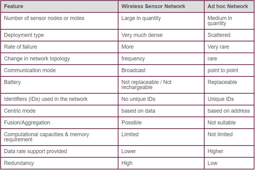 Table I Differences Between an Adhoc Network & a Wireless Sensor Network
3. Limitations of a WSN
There are many challenges encountered when attempting to implement a wireless sensor network. The sensor nodes communicate over wireless, lossy connections with no structure. Another challenge is the restricted and non-renewable energy supply of the sensor nodes (usually in the form of batteries). In order to fully utilize the lifetime of the network, the procedures need to be designed from the start with the aim of efficient management of the energy resources.
3.1 Fault Tolerance
Sensor nodes are susceptible and are constantly placed in dangerous environments. Nodes can fail due to hardware problems or physical damage or even by draining their batteries. It is expected that the node failures are to be much higher than wired or infrastructure-based wireless networks. The protocols organized in a sensor network should be able to detect these failures as soon as possible and be durable enough to handle quite a large number of failures while maintaining the overall functionality of the network.
3.2 Scalability
Scalability is an important issue in the design of routing protocols for WSNs. A routing protocol is considered to be good and effective if it is scalable to the changes in the topology of the network. The protocol should withstand and perform well with changes that may happen to the WSN. The WSN is said to be scalable if it accommodates more nodes at a later stage after the design (Noufal 2015). Sensor networks differ in their size from a few nodes to several hundred thousand. Additionally, the placement density is also different. For collecting high resolution data, the node density might reach the level where a node has several thousand neighbors in their transmission range. The protocols deployed in sensor networks need to be scalable to these levels and be able to maintain adequate performance.
3.3 Production Costs
Since nodes are considered to be disposable devices; the production cost should ideally be less than one U.S. Dollar. When deciding whether to design a wireless sensor system or use a ready-made one, some tasks need to be taken into consideration; development time, development team and costs, testing and certification requirements, manufacturing processes, equipment, volumes and costs. The figure below shows a basic comparison of building a wireless sensing system versus using a ready-made sensor node.
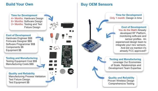
Figure 3 Using an OEM Sensor Node vs. Building Your Own
3.4 Hardware Constraints
Basically, every sensor node needs to have a sensing unit, a processing unit, a transceiver unit, and a power supply. Additionally, the nodes may have several built-in sensors or additional devices such as a location finding system to enable location-aware routing. However, every additional feature increases the cost and increases the power consumption and physical size of the node. Therefore, additional features need to be always balanced against cost and low-power requirements.
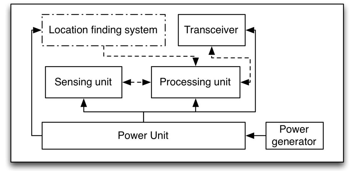
Figure 4 Sensor Node Architecture
3.5 Topology
As WSN develop through time, they still have constraints in terms of energy, computing power, memory, and communications capabilities. One major limitation is energy consumption, which is shown by the large number of algorithms, techniques, and protocols that have been utilized to conserve energy, which will extend the lifetime of the network. Topology maintenance will aid in reducing energy consumption in wireless sensor networks.
3.6 Power Consumption
A major constraint on wireless sensors networks is that sensor nodes use batteries. A second constraint is that sensors will be placed unattended and in large numbers, so that it will be difficult to change or recharge batteries in the sensors. Consequently, all systems, processes and communication protocols for sensors and sensor networks must minimize power consumption (Torres 2006). The software and hardware design needs to carefully consider the issues of efficient energy use. For instance, data compression might reduce the amount of energy used for radio transmission, but uses additional energy for computation and/or filtering.
4. Topology of Wireless Sensor Networks
A WSN is made up of nodes positioned in a location that needs to be monitored. Usually, these nodes are placed in a severe environment, and the nodes are randomly deployed. The sensed data is transmitted through the nodes up to the base stations (also called sinks or gateways). The base stations are nodes with two or more network interfaces that act as gateway between the WSN and the user network. The base station usually collects and processes the data from the network sending the required information to the user. A sensor node can communicate directly to the base station (single-hop) or use a multi-hop communication passing the data through multiple nodes back to the base station. Single-hop communication usually requires long distance sending of data which uses up a lot of power. Using multi-hop communication, one may be able to reduce the transmission distance, which in-turn reduces power consumption. In multi-hop transmission, the topology of the network is key. Multi-hop network architectures are typically divided in a flat or hierarchical design as shown in Figure 5 below (Moschitta 2014).
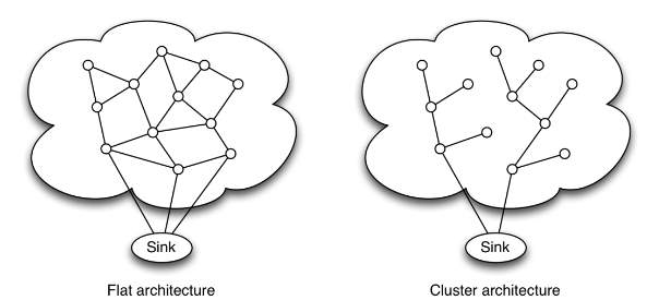
Figure 5 Multi-hop Network Architecture
4.1 Star Network
A star network is a type of topology where a single base station can send and receive data to multiple remote nodes. The sensor nodes are not capable of transmitting data to each other. The advantage of this type of network for wireless sensor networks is its simplicity, and the ability to keep the sensor node’s power consumption to a minimum. It also allows low latency communications between the sensor node and the base station. The disadvantage of the star network topology is that the base station must be within transmission range of all the individual nodes and is not as durable as other networks due to its dependency on a single node to manage the network.
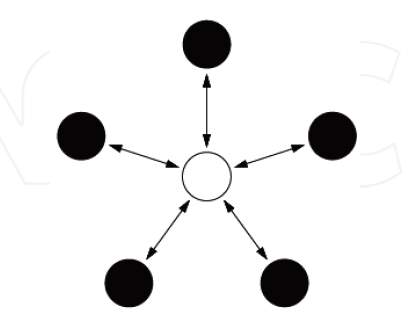
Figure 6 Star Network Topology
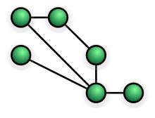
4.2 Mesh Network
A mesh network allows transmitting data to one node to other node in the network that is within its transmission range. This allows for multi-hop communications, that is, if a node wants to send a message to another node that is out of radio communications range, it can use a node close by to transmit data to the desired node or back to the base station. This topology has the advantage of redundancy and scalability. If an individual node fails, a remote node still can communicate to any other node in its range. Also, the range of the network can be extended by adding more nodes to the network. The disadvantage of this type of network is in power consumption. The nodes that use multi-hop communications usually have higher power consumption than the nodes that just use single hop. Furthermore, as the number of communication hops to a destination increases, the time to transmit the data increases as well, increasing power consumption.
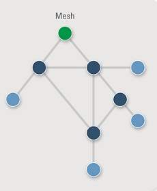
Figure 7 Mesh Network Topology
4.3 Cluster Tree Network
A cluster/tree topology is a hybrid star–mesh architecture. It takes advantage of the low power consumptions and simple architecture of a star topology, as well as the extended range and fault tolerance of a mesh one. However, there probably exists some lag between nodes, (Xu 2014). This type of topology provides a durable and useful communications network. It also has the ability to keep the sensor nodes power consumption to a minimum. In this network topology, the sensor nodes with lowest power to do not have the ability to transmit data. This allows for minimal power consumption to be maintained. Still, other nodes on the network have multi-hop capability, giving them the ability to forward data from the low power nodes to other nodes on the network. Generally, the nodes with the multi-hop capability are higher power, and they are often connected to continuous power source.
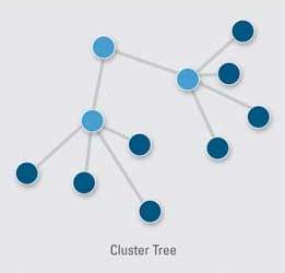
Figure 8 Cluster Tree Network Topology
5. Protocols of a WSN
In a WSN, the main purpose of a sensor node is to sense the required information and send it back to the base station in a multi-hop layout. For computing the routing path from the source node to the base station there is huge numbers of proposed routing protocols exist. The design of routing protocols for WSNs must consider the power and resource limitations of the network nodes, the time-varying quality of the wireless channel, and the possibility for packet loss and delay. To address these design requirements, several routing strategies for WSNs have been proposed.
5.1 Flat network Architecture
The first class of routing protocols uses a flat network architecture in which all nodes are peers. A flat network architecture provides many advantages, including minimal effort to maintain the infrastructure and the potential for the discovery of multiple routes between communicating nodes for error uncertainty
5.2 Imposing a Structure Architecture
A second class of routing protocols imposes a structure on the network to achieve energy efficiency, stability, and scalability. In this type of architecture, network nodes are organized in clusters in which a node with higher residual energy. The cluster head is responsible for coordinating activities within the cluster and forwarding information between clusters. Clustering has potential to reduce energy consumption and extend the lifetime of the network.
5.3 Flooding
Flooding is a popular technique used for path discovery and information distribution in WSNs. The routing technique of flooding is simple and does not use expensive topology methods. Flooding is when each node receiving a data or control packets sends the packet to any nearby sensor nodes. After the data has been transmitted, a packet follows all possible paths. Unless the network is disconnected, the packet will eventually reach its destination. Even if the topology has been altered, the packet transmitted follows a new route.
5.4 Gossiping
Similar to flooding, gossiping uses a simple forwarding method for the transmitted data and does need expensive topology maintenance or costly algorithms. Compared to flooding, where a data packet is transmitted to all neighbors, gossiping needs each node to send the incoming packet to a sensor node nearby. When receiving the packet, the sensor node selected randomly chooses another sensor node and sends the packet to the sensor node chosen. This process continues until the packet reaches its intended destination or the maximum hop count is exceeded.
5.5 Direct Diffusion
Directed diffusion is a data-centric routing protocol for information gathering and distribution in WSNs. The main objective of this protocol is to achieve significant energy savings in order to extend the lifetime of the network. To achieve this objective, directed diffusion keeps interactions between nodes, in terms of message exchanges, localized within limited network area. Using localized interaction, direct diffusion can still realize strong multi-path delivery and adapt to a minimal subsection of network paths. This type of protocol, combined with the ability of the nodes to aggregate response to queries, results into significant energy savings.
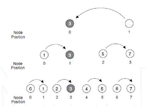
Figure 10 Chain Based Data Gathering Using Directed Diffusion
6. Security Flaws Using WSNs
Security issues in sensor networks depend on the need to know what we are going to protect. Confidentiality is the ability to conceal message from a passive attacker, where the message communicated on sensor networks remain confidential. Integrity refers to the ability to confirm the message has not been tampered, altered or changed while it was on the network. Authentication Need is to know if the messages are from the node it claims to be from, determining the reliability of message’s origin. Availability is to determine if a node has the ability to use the resources and the network is available for the messages to move on. Freshness implies that receiver receives the recent and fresh data and ensures that no one can replay the old data.
6.1 Layering Based Security Approach
6.1.1 Application Layer
Data is collected and managed at application layer therefore it is important to ensure the reliability of data. One technique is a resilient aggregation scheme which is appropriate to a cluster based network where a cluster leader acts as an aggregator in sensor networks. However, this technique is applicable if the aggregating node is in the range with all the source nodes and there is no intervening aggregator between the aggregator and source nodes. To prove the validity of the aggregation, cluster leaders use the cryptographic techniques to ensure the data reliability.
6.1.2 Network Layer
Network layer is responsible for routing of messages from node to node, node to cluster leader, cluster leaders to cluster leaders, cluster leaders to the base station and vice versa.
6.1.3 Data Link Layer
Data link layer does the error detection and correction, and encoding of data. Link layer is vulnerable to jamming and DoS attacks. TinySec has introduced link layer encryption which depends on a key management scheme. However, an attacker having better energy efficiency can still perform an attack. Protocols like LMAC have better anti-jamming properties which are a viable countermeasure at this layer.
6.1.4 Physical Layer
The physical layer emphasizes on the transmission media between sending and receiving nodes, the data rate, signal strength, frequency types are also addressed in this layer. Ideally FHSS frequency hopping spread spectrum is used in sensor networks.
7. Methodology
The goal of this project is to provide accurate location estimation based on multiple sources of information. The smart location system will consist of a small number of fixed nodes with known location, mobile wirelesses sensor nodes, and a limited number of mobile nodes with both ultrasound and sensor networking capabilities. The first phase of this project is to identify different types of RF information (received signal strength, time of arrival, angle of arrival, location of neighbouring nodes, etc.) that can be used for location estimation. This involves processing the RF signal as well as designing mechanisms to share and exchanges location from neighbouring nodes.
The phase after that will be to develop an algorithm to connect and network these mobile nodes together. One of the best algorithms used nowadays for networking is the Mesh network. In a Mesh network, each node sends data for the network. The technique used in Mesh networking is called the Routing Technique.
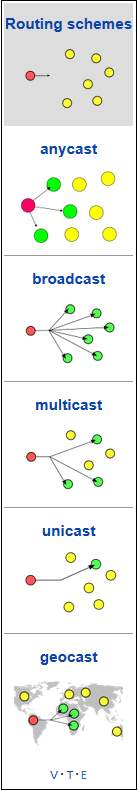
7.1 Routing
With routing, the message is transmitted in a path by hopping from one node to another until it reaches its destination. Self-healing techniques such as Shortest Path Bridging are used here to ensure that the message’s paths are available and so the message can reconfigure itself around broken paths.
There is more than one way to deliver messages using the routing technique:
- Unicast: In unicast, the message is delivered to a specific individual node.
- Anycast: In anycast, the message is delivered to anyone in a group of nodes, usually to the one nearest to the source.
- Multicast: In multicast, the message is delivered to a group of nodes that have shown interest in receiving the message.
- Geocast: In geocast, the message is delivered to a geographic area.
- Broadcast: in broadcast, the message is delivered to all nodes in the network.
8. Testing
8.1 Connecting the Hardware
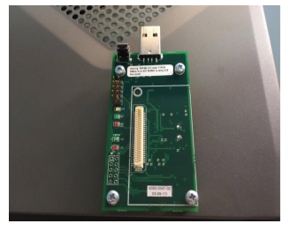
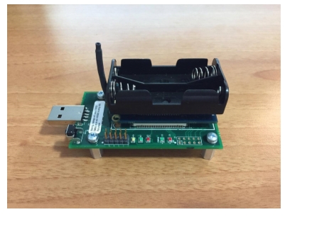
 When connecting the IRIS – XM2110 on the MIB520, make sure to have the XM2110 on the off position and with no batteries on. Damage will occur if IRIS – XM2110 battery is on and MIB520.
is using USB bus power.
8.2 Starting MoteView 2.0
- Click on Program Mote > Settings > Interface Board…

Figure 16 Interfacing the Board
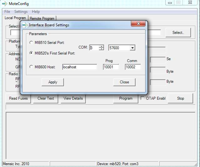
Figure 17 Configuring The Board as a Base Station
- The MIB520 COM port drivers will automatically install two sequential ports on the PC when connected. The low-numbered port will be used for programming the node and the high-numbered node will be used for communication.
- To check the ports, search Device Manager > Ports (COM & LPT).

Figure 18 Checking Which COM Ports are Being Used
- Here, COM3 was used for programming the node and COM4 was used for communication.
- Choose MIB520’s First Serial Port and in the project’s case, COM3 must be selected as the serial port.
8.3 Programming
- The pre-compiled XMESH applications installed with MoteView are located in C > Program Files or Program Files (x86) > Memsic > MoteView > Xmesh > iris > MTS400.
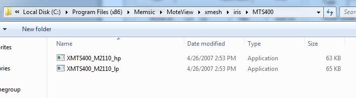
Figure 19 Uploading The Required HP File
- After uploading the hp file, the binary scan feature built into MoteView will display the default parameters programmed into the application.
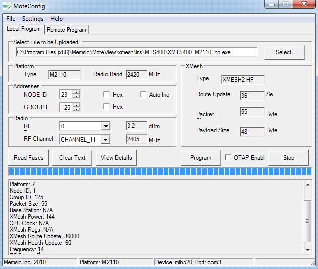
Figure 20 Final Step in Configuring the MIB520
- The Base Station must be programmed with a NODE ID of 0. Remote nodes must be programmed with none-zero NODE ID.
- The default parameters can be changed by the user if needed.
- Press Program for the firmware to download and the software will configure it into the mote.
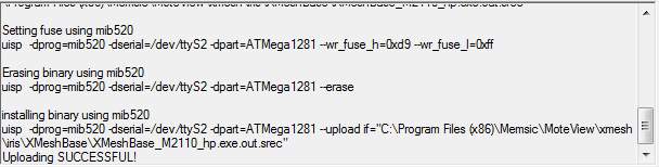
Figure 21 Mote Successfully Being Configured
- Select File > Connect to WSN… From Select Operation Mode tab, check on Acquire Live Data as operation mode and Local from Acquisition Type Tab.

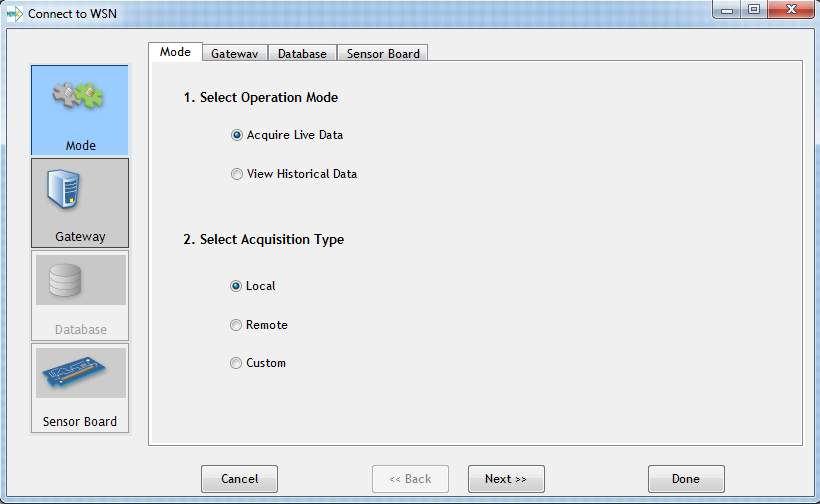
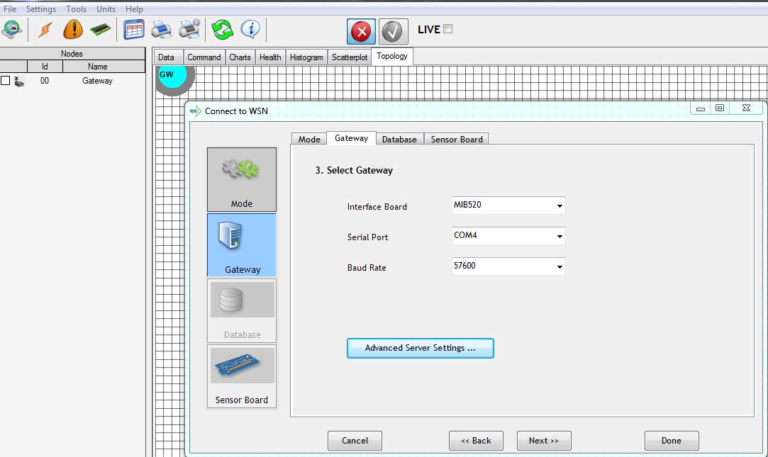
Figure 23 Select the highest COM port for programming
- Choose the right Interface Board and the higher Serial Port
- From the Gateway tab, choose your Interface Board.
- Here, MIB520 is being used, so set the higher of the two COM ports that were installed by the MIB520 driver which is COM4 (Communication Port).
- In the Senor Board tab, choose the right application name which is MTS400, the sensor board that is being used.
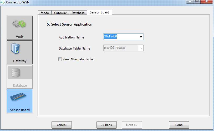
Figure 24 Selecting the Compatible Sensor Board
- Press Done.
8.4 Errors faced
- One of the errors that might occur when trying to configure the hardware is the software crashing. This can happen due to configuring the wrong COM. COM 3 should have been used for programming the node in this case.

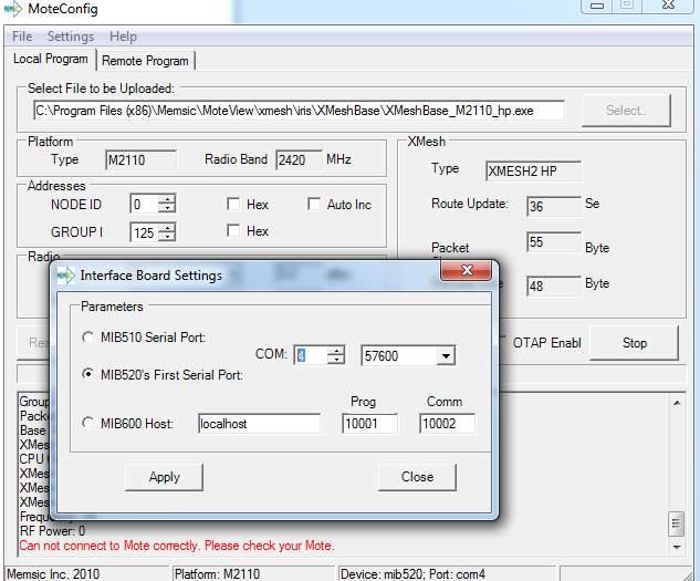
Figure 25 Lower COM Port (COM3) must be chosen
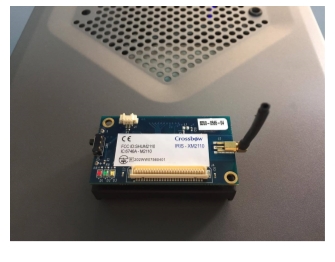
8.5 MTS400
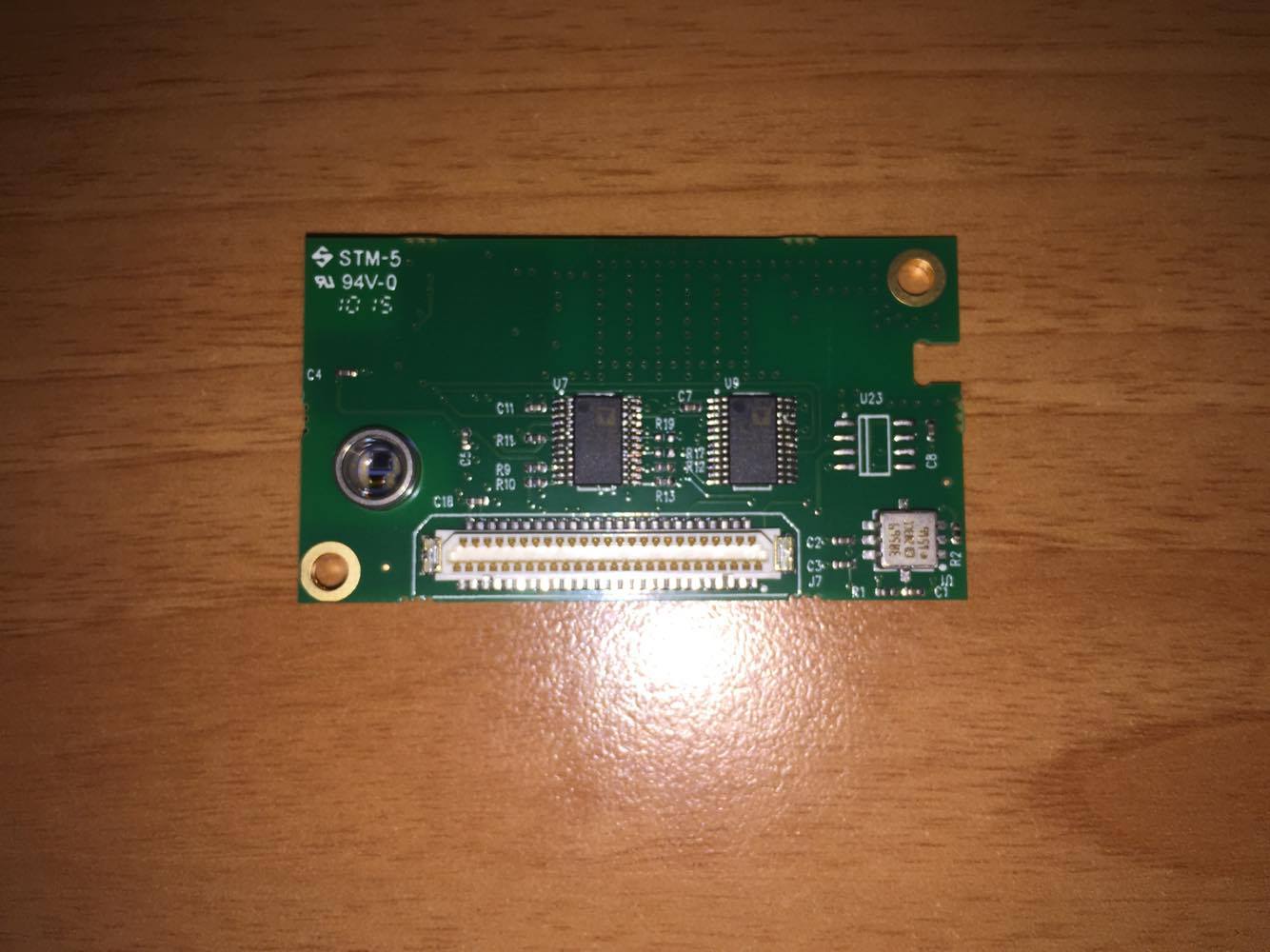
Figure 26 MTS400 Sensor Bottom View
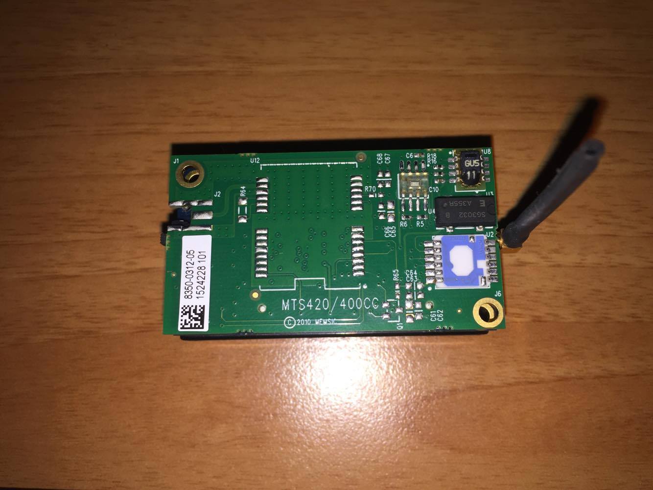
- Connect the MTS400 board to the XM2110 using the female connector. Turn on the XM2110 wireless node and the sensor should start working immediately.
- The sensor board should now appear on the left side of MoteView (Green wireless antenna).
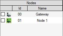
Figure 29 List of Nodes in Left Side Tab
- On the right side of MoteView, click on Data and the sensor board’s parameters should appear.
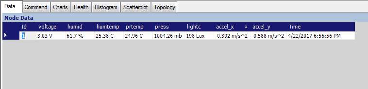
Figure 30 Sensor Node’s Parameters
- At the bottom of MoteView, server messages update you whenever a calibration occurs.
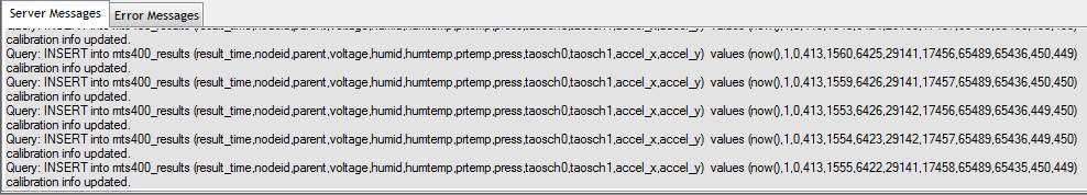
Figure 31 Regular Updates of Calibration
8.6 Testing MTS400 Capabilities
- In MoteView, click on Topology then on the right side, click on voltage.
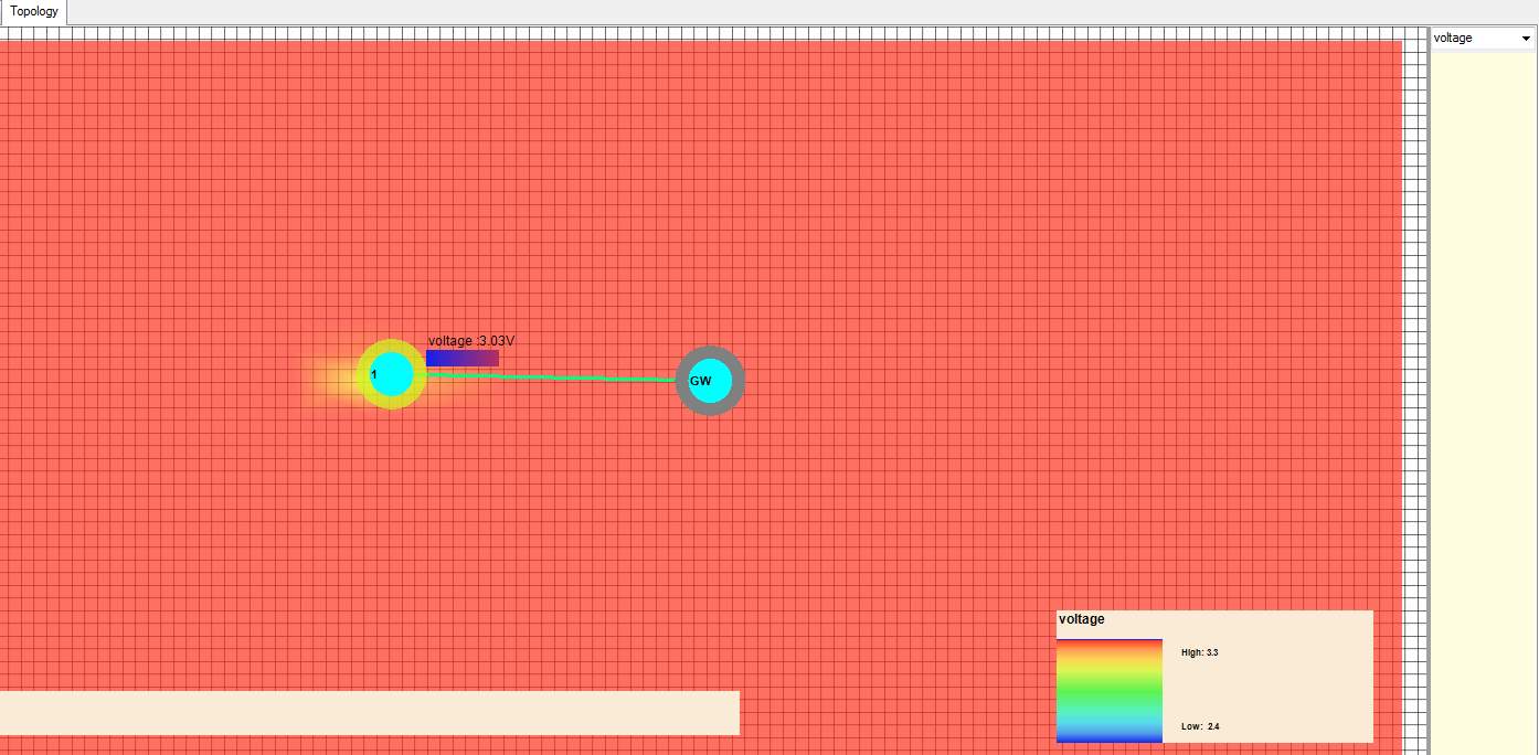
Figure 32 Voltage of Batteries Being Displayed
- Here, the sensor shows what voltage is being used. The wireless mote is using two AA batteries (1.5V each); therefore, the sensor is showing 3.03V.
- Next, click on humid.
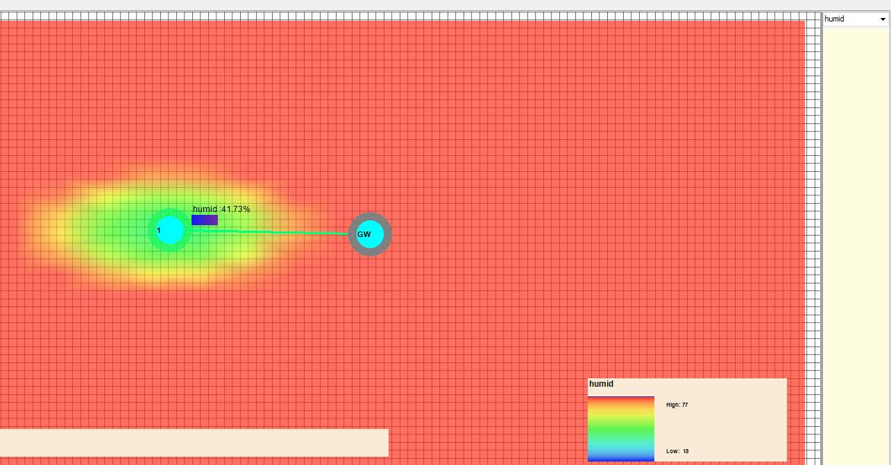
Figure 33 Humidity Data being Monitored
- The sensor here shows what the current humidity is. It also tells if the humidity is high or low.
- Next, click on hemtemp

Figure 34 Surrounding Temperature being Monitored
- Here, the sensor shows the current temperature in celsius. It can also show the temperature in other units suchs as fahrenheit or kelvin.
- Next, click on “Press”.
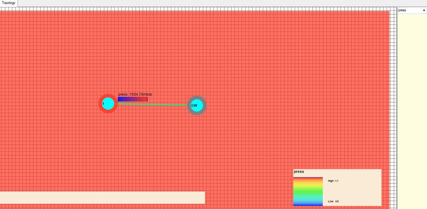
Figure 35 Pressure Data being Displayed
- Press shows the amount of pressure on the sensor in Millibar. It can also show the pressure in atmosphere, pascal and even pounds per square inch (PSI).
- Next, press on lightc.
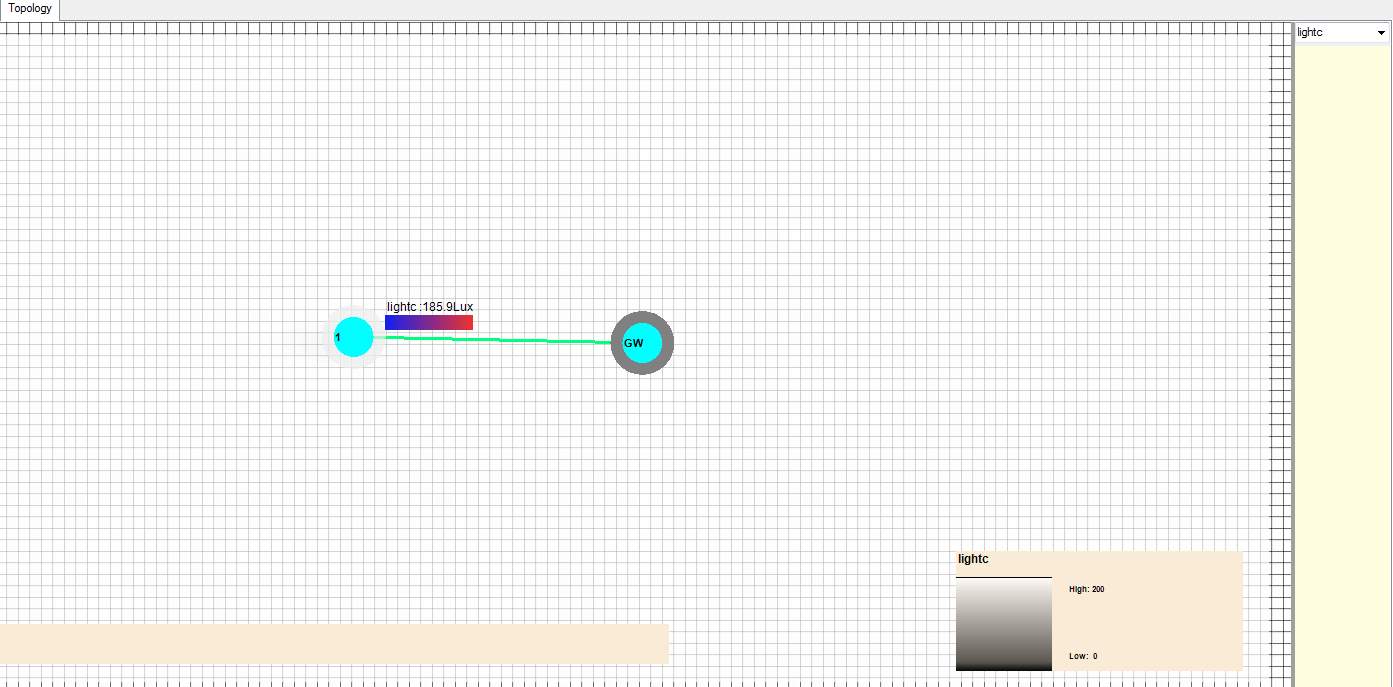
Figure 36 Amount of Light Being Detected
- Here, the sensor shows if it is being exposed to high amount of light or low amount of light. Lux, the SI unit of illuminace, is used to measure the intensity of light.
- Below, is a simple expirement that prooves the sensor is doing its job.
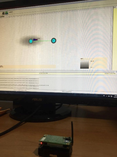
Figure 37 Room’s Light being Displayed on the GUI
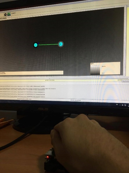
Figure 38 Displaying Total Darkness When Sensor is Covered
- The picture on the left is before covering the sensor board, light intensity measured here is 163.58 Lux. The picture on the right is after covering the sensor board, light intensity measured here is 8.55 Lux.
9. Results and Discussion
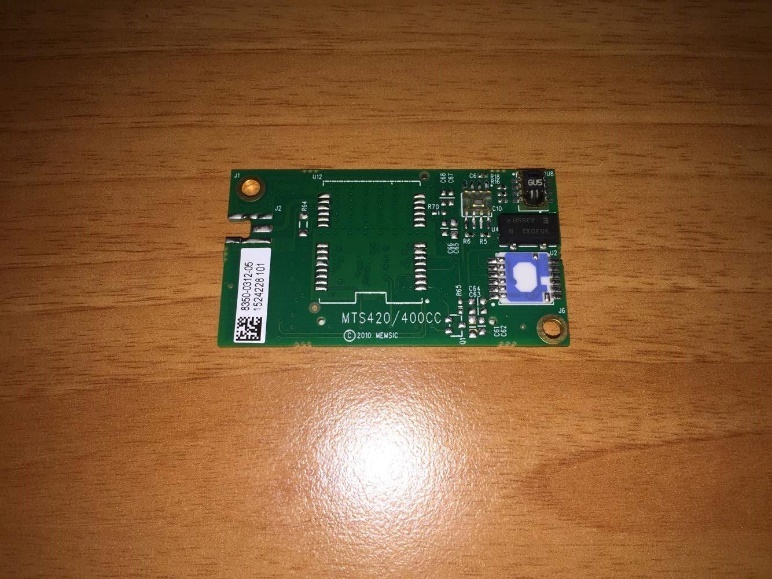
At the beginning of the project, ACK provided an MIB520 USB programmer and two XM2110CB Nodes. It was the team’s job then to do some research about which sensor to work with. Memsic has a huge variety of sensor boards which all are supported with drivers that works with the software they provided. At the end, two sensor boards were choses that would be a perfect fit for this project. The MTS420/400 Environmental Sensor Board it was.
The table below shows the difference between MTS420, MTS400 & the rest of the sensors.
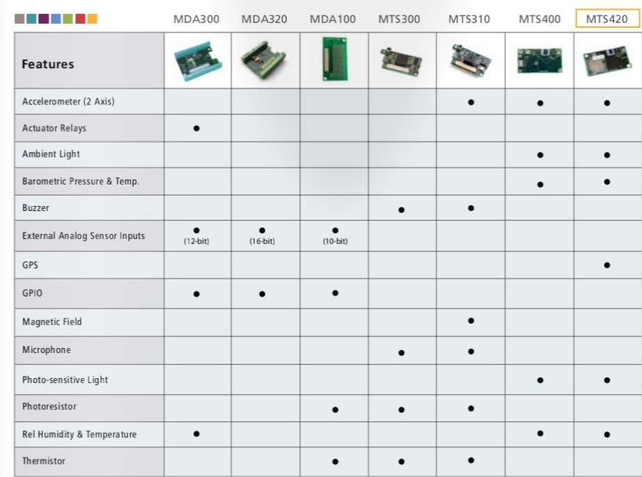
The MTS400 and MTS420 are equipped with the same environmental sensing capabilities, with the least having a GPS system installed.
These sensor boards have one of the best and latest generations of IC’s. The sensor boards are equipped with an extended battery-life which makes them energy-efficient.
These sensor boards are intended for a wide variety of applications such as underground piping installations or to monitor workers from earthquakes. Applicable industries include Agricultural, Industrial and more.
9.1 Problems Faced
The main problem faced here was when ordering the sensor board. The MTS420 was the most suitable sensor board for this project because of the built-in GPS. However, when ordering the sensor, Memsic said that it would take around two months for the sensor board to arrive as it wasn’t available in their stock.
10. Future Development
The fundamental of this project is to develop a proof-of-concept system using wireless nodes and sensors to demonstrate the viability of the proposed project indoors as well as outdoors. Once the viability of the project has been achieved, the next step is to develop small, low-powered energy efficient sensors and wireless nodes. The indicated algorithms will be tested on this hardware for their suitability. Further optimization of the algorithms might be required for the adapting to the improved hardware.
11. Conclusion
In conclusion, the outcome of this project did not meet the initial expectations that were developed at the inception of this research. Although, some requirements were eventually met towards the end of the timeline. The problems that were faced during the time of developing a wireless sensor network with location based attributes were due to the time constraints and miscommunications with the original equipment manufacturer (OEM). A wireless sensor network’s purpose is to monitor data in the location the sensor nodes are deployed in. The sensor nodes collect relevant information such as temperature, light, humidity, and in this project’s case, location as the main feature. That information is sent back to the base station for the user to observe. This project’s main objective was to develop multiple firefighting robots combined with the sensor nodes to display location and other relevant data. Unfortunately, the outcome took a slight detour. Due to the OEM not having the MTS 420 sensor board (which has the location based sensor on it); the MTS 400 was settled upon (which is identical to the MTS 420, but without the GPS feature).
Even though the main objective was not achieved; a solid basic understanding of how wireless sensor networks was accomplished. The strengths of this project on developing a wireless sensor network included developing a real-life scenario where are wireless sensor network could effectively be implemented in. Another strength of this project was now the firefighting robot’s application can be extended from the basic functions of just being deployed in a harsh environment and probably getting damaged to one that can receive and act on data about the environment it operates in. Another strength of this project is that even though the network is being limited to one sensor node, it can easily accommodate another sensor node to expand the network. Adding a new sensor node is simple; just repeat the process of adding a node in MoteView, and the network will connect by itself.
Limitations of developing wireless sensor network for a firefighting robot were due to the fact that the required hardware were not accessible within the time frame given to complete the project. Another drawback relating to the sensor nodes is the fact since they are being deployed in harsh environments such as burning buildings; the probability of the nodes getting damaged is high. The likelihood of having to replace the sensor nodes when they are damaged is high. Since the sensor node that has location based properties was unavailable to attain; the main purpose of this project had to be altered. Developing this wireless sensor network was supposed to act as an alternative to a GPS where a GPS was not accessible. Alternative solutions were looked in to, such as developing a GPS system using an Arduino board and a GPS sensor. But, that defeated the main purpose of a wireless sensor network; which was to be portable, and wireless. Having a big device that had high power consumption would have rendered the concept of a WSN redundant.
With all the knowledge garnered from researching and implementing a wireless sensor network; there are measures that could have been taken to achieve the results intended at the beginning of the projects. One such measure was to order the required number of nodes and the required sensors from Memsic in first day. Since the level of knowledge of WSNs at day one was very minimal; it took some time to realize what components were required to operate an effective wireless sensor network. Another method to improve the outcome of this project was to change the objective of the WSN from location based to collect data on other information, such as temperature, light, or humidity. Implementing a scenario such as a greenhouse in which a farmer can collect necessary information and use the computer to alter some variables within the greenhouse.
Overall, developing a wireless sensor network proved to be a challenging feat, but provided knowledge in a relatively new field which has not been implemented in the mainstream. Discovering the many useful applications, a WSN could be deployed in because of its cheap price to implement, portability, and low power consumption. The main objective of location based applications was not achieved, but a WSN has many more applications and benefits to be taken advantage of. For future work; ensure solid communication with the OEM Memsic to receive the correct hardware to implement a WSN. Even though this project implemented one sensor node, a truly effective WSN will utilize multiple sensor nodes to collect data. Wireless sensor networks have the potential of bringing a new communication standard which enables setting up an intelligent network capable of performing tasks that are required by the user. Continuing research on WSNs will greatly impact daily life in a positive way.
12. Bibliography
Cecílio, J. & Furtado, P., 2016. Wireless Sensor Networks Basic Components. Assignment Point. Available at: http://www.assignmentpoint.com/science/eee/wireless-sensor-networks-basic-components.html [Accessed April 20, 2017].
M. A. Labrador, P. M. Wightman. Topology Control in Wireless Sensor Networks. Springer
Science + Business Media B.V. 2009.
Tiwari, P. et al., 2015. Wireless Sensor Networks: Introduction, Advantages, Applications and Research Challenges. HCTL Open International Journal of Technology Innovations and Research (IJTIR). Available at: http://ijtir.hctl.org/vol14/IJTIR_Article_201504011.pdf [Accessed April 22, 2017].
Nack, F., An Overview on Wireless Sensor Networks. Fachbereich Mathematik und Informatik. Available at: http://www.mi.fu-berlin.de/inf/groups/ag-tech/teaching/2008-09_WS/S_19565_Proseminar_Technische_Informatik/nack09verview.pdf [Accessed April 22, 2017].
Rouse, M., What is ad-hoc network? – Definition from WhatIs.com. SearchMobileComputing. Available at: http://searchmobilecomputing.techtarget.com/definition/ad-hoc-network [Accessed April 22, 2017].
Anon, RF Wireless World. difference between Wireless Sensor Network vs Ad hoc Network. Available at: http://www.rfwireless-world.com/Terminology/Wireless-Sensor-Network-vs-Ad-Hoc-Network.html [Accessed April 22, 2017].
K.P, N., 2015. Wireless Sensor Networks – Scalability and Performance Issues: A Review. International Journal of Computer Science and Technology. Available at: http://www.ijcst.com/vol61/1/31-Noufal-K-P.pdf [Accessed April 22, 2017].
Walters, B., 2015. Designing low-cost wireless sensor networks for real-world applications. Electronic Component News. Available at: https://www.ecnmag.com/article/2012/08/designing-low-cost-wireless-sensor-networks-real-world-applications [Accessed April 22, 2017].
Torres, M.C.A.D.G.C., 2006. ENERGY CONSUMPTION IN WIRELESS SENSOR NETWORKS USING GSP . D-Scholarship@Pitt. Available at: http://d-scholarship.pitt.edu/7682/1/callemariag072606.pdf [Accessed April 22, 2017].
Moschitta, A. & Neri, I., 2014. Power consumption Assessment in Wireless Sensor Networks. Power consumption Assessment in Wireless Sensor Networks | InTechOpen. Available at: https://www.intechopen.com/books/ict-energy-concepts-towards-zero-power-information-and-communication-technology/power-consumption-assessment-in-wireless-sensor-networks [Accessed April 22, 2017].
Xu, G., Shen, W. & Wang, X., 2014. Applications of Wireless Sensor Networks in Marine Environment Monitoring: A Survey. MDPI. Available at: http://www.mdpi.com/1424-8220/14/9/16932/htm [Accessed April 22, 2017].
Cite This Work
To export a reference to this article please select a referencing stye below:
Related Services
View all


Related Content
All TagsContent relating to: "Information Technology"
Information Technology refers to the use or study of computers to receive, store, and send data. Information Technology is a term that is usually used in a business context, with members of the IT team providing effective solutions that contribute to the success of the business.
Related Articles

DMCA / Removal Request
If you are the original writer of this dissertation and no longer wish to have your work published on the UKDiss.com website then please: