Smart Bin for Smart Cities System Requirements
Info: 14346 words (57 pages) Dissertation
Published: 11th Dec 2019
Tagged: Environmental Studies
1. INTRODUCTION
1.1 Purpose of the system:
The overflowing municipal garbage bins, are not cleared anytime. As a result the consequences are severe. This results in land pollution, diseases get spread, also unhygienic conditions arise for people, and ugliness to that place. There must be a system that gives prior information of the filling of the bin that alerts the authorized member, so that they can clean the bin on time and safeguard the environment. To avoid all such situations we intend to propose a solution for this problem “Smart Bin for smart cities”, which will alarm and inform the authorized person when the garbage bin is about to fill.
1.2 Existing System:
In this project Ultrasonic sensors are used to detect the level of bin. Load cell will be placed at the bottom of bin. These are used as secondary sensors. A Node-Mcu module is used to communicate with server room. When the bin is about to fill, with the help of Node-Mcu module, a message signal will be sent. The GPS module will help to identify the location of garbage bin. The message signal will also contain the coordinates of bin which will be provided by GPS module. An Arduino will be programmed in such a way that it would control the bins. All these bins can be monitored on the respective platform.
1.3 Proposed system:
As an extension to this project we will send complete sensor data to the cloud. Multiple bins are added in this system as a part of smart cities. All the bins are monitored through the webpage. Data analytics and visualization can be done in the webpage.
2. SYSTEM REQUIREMENTS:
2.1 HADWARE REQUIREMENTS:
1. Arduino Nano
2. Ultrasonic Sensor
3. NodeMcu-6
4. Load cell
5. Neo-6 GPS
2.2 SOFTWARE REQUIREMENTS:
1. Embedded C 2. Html
3. SYSTEM ANALYSIS
3.1 FEASIBILITY STUDY:
Feasibility is an evaluation of the proposal is to determine the difficulty in carry out a task. The feasibility precedes technical development and project implementation, that is, a feasibility study is a evaluations or analysis of the potential impact of the proposed project.
3.2 Types of Feasibility
The main objective of Feasibility study is to uncover the strengths and weaknesses of an existing business opportunities and threats as presented by the environment, the resources required to carry through, and ultimately the prospects for success. The designed feasibility study provides historical background for business, operation and management details, financial thesis, describes service accounting statements and any obligations for tax. Development in technical and project implementation are generally the studies of feasibility
3.2.1Technology and system feasibility
The Input, Output, procedures, Fields are the requirements of system which is the outline design. The companies capability regarding hardware, expertise, software of having ability to complete the project, the Technological feasibility determines. The Following should be considered while writing the report on Feasibility:
Technically and legally feasibility should be concerned, at this level.
3.2.2 Economic feasibility
The most frequent method, for evaluating the system efficiency is Economic analysis More commonly known as cost/benefit analysis, the procedure is to determine the benefits and reserves that are expected from a candidate system and compare them with costs. If benefits be more important than costs, then the decision is made to design and put into practice .The capitalist should weighs the cost against profits before-hand.
Cost-based analysis: The cost and benefit are identified as follows: 1. growth costs; and 2. in use costs. This is the study of the costs to be incurred in the system and the profit derivable out of the system.
Time-based analysis: This is an study of the time essential to accomplish a return on reserves The potential value of a project is also a factor.
3.2.3 Legal feasibility
Determine whether the projected system conflict with legal requirements, e.g., a data processing system must meet the terms with the local Data Protection Acts.
 Functions:
 The type 2 driver is not written entirely in java as it interfaces with non-Java code that makes the final database calls. The driver is compiled for use with the particular operating system. For platform interoperability, the Type 4 driver, being a full-Java implementation, is preferred over this driver.
However the type 2 driver provides more functionality and better performance than the type 1 driver as it does not have the overhead of additional ODBC function calls.
Advantages:
The type 2 driver is not written entirely in java as it interfaces with non-Java code that makes the final database calls. The driver is compiled for use with the particular operating system. For platform interoperability, the Type 4 driver, being a full-Java implementation, is preferred over this driver.
However the type 2 driver provides more functionality and better performance than the type 1 driver as it does not have the overhead of additional ODBC function calls.
Advantages:
 This differs from the type 4 driver in that the protocol conversion logic resides not at the client, but in the middle-tier. Like type 4 drivers, the type 3 driver is written entirely in Java. The same driver can be used for multiple databases. It depends on the number of databases the middleware has been configured to support. The type 3 driver is platform –independent as the platform-related differences are taken care by the middleware. Also, making use of the middleware provides additional advantages of security and firewall access.
Functions:
This differs from the type 4 driver in that the protocol conversion logic resides not at the client, but in the middle-tier. Like type 4 drivers, the type 3 driver is written entirely in Java. The same driver can be used for multiple databases. It depends on the number of databases the middleware has been configured to support. The type 3 driver is platform –independent as the platform-related differences are taken care by the middleware. Also, making use of the middleware provides additional advantages of security and firewall access.
Functions:
 Functions:
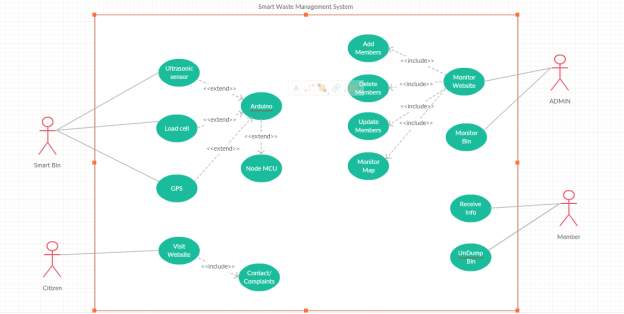
 Fig: Use Cases
A node is a physical element.It exists at the runtime and represents a computational resource which has atleast some memory and also the processing capability.
Fig: Use Cases
A node is a physical element.It exists at the runtime and represents a computational resource which has atleast some memory and also the processing capability.
 Fig: Nodes
2. Behavioral things are the dynamic parts of UML models. The behavioral thing used is:
Interaction:
An interaction is a behaviour that consists a set of messages exchanged among a set of objects within a particular context to accomplish a specific purpose. It involves a number of other elements, including the behaviour of the messages and the connection between the objects
Fig: Nodes
2. Behavioral things are the dynamic parts of UML models. The behavioral thing used is:
Interaction:
An interaction is a behaviour that consists a set of messages exchanged among a set of objects within a particular context to accomplish a specific purpose. It involves a number of other elements, including the behaviour of the messages and the connection between the objects
 Fig: Messages
2. Relationships in the UML:
There are four kinds of relationships in the UML: • Dependency• Association• Generalization• Realization. A dependency is a semantic relationship between two things in which changing one thing affects the other thing which means both are dependant on each other. It is represented by a dotted line with an arrow at one end.
Fig: Messages
2. Relationships in the UML:
There are four kinds of relationships in the UML: • Dependency• Association• Generalization• Realization. A dependency is a semantic relationship between two things in which changing one thing affects the other thing which means both are dependant on each other. It is represented by a dotted line with an arrow at one end.
 Fig: Dependencies
An association comes under structural relationship. It describes a setof links and the connection between objects. An Aggregation is a special kind of association. It represents a relationship between a whole and its parts.
Fig: Dependencies
An association comes under structural relationship. It describes a setof links and the connection between objects. An Aggregation is a special kind of association. It represents a relationship between a whole and its parts.
 Fig: Association
A generalization is a specialization-generalization relationship in which objects of specialized elements- child elements helps in substituting the generalized - parent elements one works on it.
Fig: Association
A generalization is a specialization-generalization relationship in which objects of specialized elements- child elements helps in substituting the generalized - parent elements one works on it.  Fig: Generalization
A realization is a relationship between classifiers. Here on classifier specifies the other works on.
Fig: Generalization
A realization is a relationship between classifiers. Here on classifier specifies the other works on.  Fig: Realization
4.1 UML DIAGRAMS
A diagram is a graphical presentation of a set of elements.It represents a connected graph. UML consists of nine such diagrams. Unified Modeling Language (UML) is probably the most widely used notation for object-oriented methods. UML is a standar language for writing Software Blueprints.
The UML may be used to visualize, specify, construct and document the artifacts. A modeling language focuses on the physical and conceptual representation of a system. Modeling is the process of designing of the software applications before coding. Modeling plays an essential part in large,medium and small projects as well.A project without a good model cannot assure the success.It ensures the project's success and helps in correct and complete business functionality. Modeling should be done according to the needs of the client or end user.
The UML diagrams are as follows:
Fig: Realization
4.1 UML DIAGRAMS
A diagram is a graphical presentation of a set of elements.It represents a connected graph. UML consists of nine such diagrams. Unified Modeling Language (UML) is probably the most widely used notation for object-oriented methods. UML is a standar language for writing Software Blueprints.
The UML may be used to visualize, specify, construct and document the artifacts. A modeling language focuses on the physical and conceptual representation of a system. Modeling is the process of designing of the software applications before coding. Modeling plays an essential part in large,medium and small projects as well.A project without a good model cannot assure the success.It ensures the project's success and helps in correct and complete business functionality. Modeling should be done according to the needs of the client or end user.
The UML diagrams are as follows:
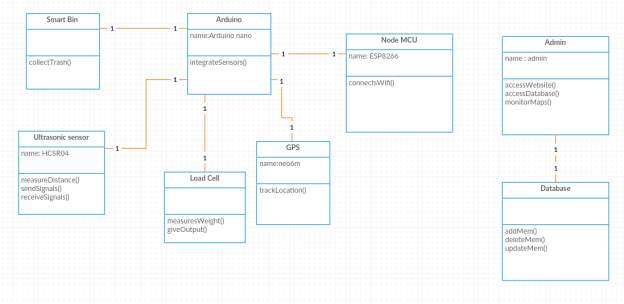 Class Diagram: The class diagram is used to define a detailed design of the system in which the actors are classified into set of interconnected classes. Each class provides a set of certain functionalities which can be termed as methods of the classes. Each class is identified to be unique as they have a different set of attributes.
6. SOFTWARE ENVIRONMENT
6.1 ARDUINO
Arduino is an open-source prototyping platform.It acts as an interface between hardware and software. The Arduino Integrated Development Environment(IDE) or and Arduino Software contains a text editor for writing code, a message area referred to as a Serial Monitor, a system console where in the warnings, errors and the compilation details are shown, a toolbar with buttons for common functions and a series of menus. It connects to the Arduino and hardware to upload programs and communicate with them.
Programs written using Arduino Software are referred to as sketches. These sketches are written in the text editor and are saved with the file extension .ino. The editor involves a feature for cutting/pasting and for searching/replacing text. The message area gives feedback while saving,compiling and exporting. It also displays the errors. The system console displays text output by the Arduino Software (IDE), including complete error messages and other information. The bottom right-hand corner of the window displays the configured board and serial port. The toolbar buttons allow you to verify and upload programs, add required libraries,create and save sketches, and open the serial monitor.
The following are the buttons displayed on the editor
Class Diagram: The class diagram is used to define a detailed design of the system in which the actors are classified into set of interconnected classes. Each class provides a set of certain functionalities which can be termed as methods of the classes. Each class is identified to be unique as they have a different set of attributes.
6. SOFTWARE ENVIRONMENT
6.1 ARDUINO
Arduino is an open-source prototyping platform.It acts as an interface between hardware and software. The Arduino Integrated Development Environment(IDE) or and Arduino Software contains a text editor for writing code, a message area referred to as a Serial Monitor, a system console where in the warnings, errors and the compilation details are shown, a toolbar with buttons for common functions and a series of menus. It connects to the Arduino and hardware to upload programs and communicate with them.
Programs written using Arduino Software are referred to as sketches. These sketches are written in the text editor and are saved with the file extension .ino. The editor involves a feature for cutting/pasting and for searching/replacing text. The message area gives feedback while saving,compiling and exporting. It also displays the errors. The system console displays text output by the Arduino Software (IDE), including complete error messages and other information. The bottom right-hand corner of the window displays the configured board and serial port. The toolbar buttons allow you to verify and upload programs, add required libraries,create and save sketches, and open the serial monitor.
The following are the buttons displayed on the editor
It is used by artists, hackers, hobbyists, and professionals to easily design, prototype and experiment with electronic devices. Use it as a brain for your robot, and get a notification about your electricity usage in your home. An Arduino contains a microchip, which is a very small computer in which you can dump the code. You can attach sensors to it so that you can measure the conditions and take a quick action if required(like if AC is on and there is no one in the room you can either off it manually or through the application that is designed for the purpose). It can control how other objects react to those conditions.
The project is based on microcontroller board designs,produced by several vendors. Microcontollers use inputs and outputs like any other computer.The inputs captures or retrieves the information from the user or the environment while the output senses the information that is being retrieved. A switch and a sensor acts as a digital and analog input respectively into the Arduino. The object that we want to turn on or off and control could be an output. The object can be a motor or a phone and sometimes eve a computer. The Arduino provides a set of digital and analog pins (Input/Output) which acts as an interface between the sensors and the boards and other circuits connected to them. The board has a serial communication interface feature which displays the output that is being generated by the sensors and a Universal Serial Bus i.e, a USB to load the programs into the computers. For programming the microcontrollers, the Arduino project provides an integrated development environment based on computer programming language named Processing. It supports the languages C and C++.The Arduino language is very similar to C. It is almost the same language but Arduino provides a way to include libraries which makes it a bit easier than C.
The first Arduino was introduced in 2005, based on 8-bit Atmel AVR, to provide a low cost easy way for the programmers and professionals to create an environment where the devices interact with the sensors. Just like robots and motion detectors created by the commoners or the beginners. There are variety of different boards in Arduino. These are available in pre-assembled form or you can manually assemble them. The hardware design specifications are available openly allowing to be produced by anyone
6.2 ARDUINO NANO
The Arduino Nano is a small, complete and breadboard friendly based on the Atmega328 or ATmega168. It functions almost same as that of Arduino but with a different package. It lacks a DC power jack. It works with a Mini-USB cable instead of a standard one. It was being produced by Gravitech. The Arduino Nano can be powered via 5v regulated external power supply or 6-20V unregulated power supply or through Mini-USB cable,and the power source is automatically selected to highest voltage source.
There are 14 digital pins on the Nano which can be used both as an input or output. There are few functions required to be called for the functioning of these pins and they are pinMode(), digitalWrite(), digitalRead(). These pins operate with 5 volts power supply. Each pin can provide or receive a maximum of 40 mA and disconnected by default of 20-50kOhms. There are few specialized pins such as receiver(RX) and transmitter(TX). Serial: 0-RX and 1-TX. These are used to receive and transmit the data. External interrupts 2 and 3. These pins helps to trigger an interrupt, or changing the value to either low or high.Pins 3,5,6,9,10 and 11 provide 8-bit PMW output with analogWrite() function. 10-SS,11-MOSI,12-MISO,13-SCK pins support SPI communication. There is a built in LED connection to digital pin 13. When the pin is in high value LED is on and vice versa. The Nano has 8 analog inputs.By default they measure from ground to 5 volts though the range can be changed using the function analogReference() function.
There are a couple of other pins on the board:
AREF-Reference voltage for analog pins with analogReference() function.
Reset-To reset the microcontroller.
Arduino can sense the surroundings by receiving input from a variety of sensors and can effect by controlling lights, motors and other devices connected to the board. The microcontroller of the Arduino board is programmed using embedded c. These projects can be seperate or they can communicate with software which is running on a computer. Arduino is a cross-platform program. There are different instructions needed to be followed for your personal OS. To run an Arduino program on your system you have to download the file from the internet and unzip it, and then install FTDI drivers to help PC to communicate with the board. After writing your code goto Tools and then SerialPort. Select the right Serial port then compile and run it.
6.3 ULTRASONIC SENSOR
Ultrasonic sensors are used to detect the presence of nearby objects and measure the distance to them. These sensors are generally used by robots often as they help in sensing the objects and avoid collisions. They help to take an appropriate actions. It has a transmitter and a receiver. The sensor spreads in the air, sense the obstacle and immediately return. The receiver would stop timing when it received the reflected wave. The ultrasonic spread velocity is 340m/s in the air. Through the formula of speed, distance and time we can calculate the distance between the obstacle and the transmitter i.e, s= (340t)/2. The principle of ultrasonic distance measurement uses the air spreading velocity, measuring the distance between the transmitter and the obstacle and the time from launch, according to the time and velocity. This principle is same with radar. The distance measurement formula is used i.e, L= C*T. Here, L is measured distance is ultrasonic spreading velocity in air and T is the half time value from Transmitting to receiving.The modules work in this way:
The sensor have 2 transducers a speaker and a microphone. Ultrasound is a high frequency wave. A short rush of sound waves are sent out the “Transmit-transducer” and the “Receive-transducer” listens for a comeback.
These are the pins which are present on the Ultrasonic sensor
• Vcc- Operating voltage: 5.0V
• Trig- The transmit signal pin
• Echo- The received echo pin
• Gnd -Ground
Software process is as follows
• Turns the Trig pin on and off to send out a echo/sound pulse.
• Examine and calculate the time how long until the Echo pin sees the echo.
• Calculate the distance.
6.4 NODE MCU-ESP8266
ESCP is defined as Smart Connectivity Platform which helps in delivering a high performance, high integration wireless SOCS, designed for space and power controlled mobile programs and designers. It provides a supreme ability to embed WIFI capabilities within other systems or to function as a seperate application. It is a lowest cost and has minimal space requirement capacity. ESP8266EX offers a complete and independent WIFI networking solution. It can be used to host the application and to passon the WIFI network functions from another workstation. It has an integrated cache that helps in improving the system performance. It serves as a WIFI adapter and wireless internet can be added to any micro-controller with simple connectivity. ESP8266EX is one of the most integrated WIFI chips in the industry as it designed to occupy minimal PCB area. It has many other functions like integrates antenna switch, low noise receiver, filters and manages the modules. This module is often integrated with external modules and sensors so as to communicate with them through WIFI.
This module helps in connecting to the WIFI and retrieving the data. The programming and the editor interface is same as that of the Arduino.
Memory Organization
Internal SRAM and ROM of NodeMCU ESP8266Ex is embedded with memory controller. This nodeMCU can visit the memory units through interfaces like ibus,dbus,AHB. These memory units are visited upon the request. When the processor receives the requests the memory arbiter will decide the sequence according to the time.
According to the current version of SDK,SRAM space is available to users as follows:
• RAM size less than 36kB, when ESP8266 is connected to the router and working under station mode.
• The user program is stored in External SPI flash as there is no programmable ROM.
The major areas where the NodeMCU module is used are:
• Baby Monitors
• Home appliances
• Wearable Electronics
• Smart bins
• Home Automation
• IP Cameras
• Wireless control systems in industries
PULSE-WIDTH MODULATION (PWM)
ESP8266EX defines 4 PWM o/p interfaces which user can extend themselves. The software programming helps in implementing PWM interfaces.
Power Management
The chip can be put into the following states -
OFF- CHIP_PD pin is low. DEEP_SLEEP: RTC is on and the other part is off. SLEEP: RTC is operating. WAKEUP state: System enters PWR state from sleep state. ON: Clock register enables the high speed clock.
6.5 HX711
24-Bit Analog-to-Digital Converter (ADC) for Weigh Scales
DESCRIPTION:
HX711 is a 24 bit ADC that helps in weighing scales. It is connected to a programmable gain amplifier. 5V current supply is passed to this. Internal registers do not require any kind of programming. HX711 can be controlled via pins.
FEATURES
• 2 Different input channels can be selected.
• There is an ADC power supply.
• no external component.
• power-on-reset
• no programming needed
• Selectable output data rate
• supply voltage range: 2.6 ~ 5.5V
• temperature range: -40 ~ +85
6.6 LOAD CELL
A load cell is a metal designed structure that senses the force acting upon it. There are different elements on it which helps in detecting the force and gives tha accurate output. These load cells are designed so as to know the exact forces that are being applied on it ignoring the other forces. As the electrical signals sensed are very small they require specialized amplification. These load cell measures the force in one direction.
The Strain-guage converts the force applied on the load cell to Electrical signals. This help in sensing the correct forces applied on them and ignore the others.
Installation
The load cell is placed on a required surface with an arrow mark pointing downwards. This arrow mark helps in placing the load cell in correct direction. On the on side of the load cell wires are attached which are connected to the amplifier. The weight should be placed on the top of the load cell. There involves a set up which helps in getting the accurate values. This load cell should be placed in between two planks and on the alternate sides there should be a small plank. This installation gives the accurate results.
Calibration
Calibration factor helps to get the accurate weight that is acted upon the load cell. This calibration factor should be set manually as different load cells have different factor. After dumping the code to respective board and compiling the code, the serial monitor displays the values of the connected sensors. There in we can find the value of the weight and change the calibration factor in the program.
6.7 NEO-6 GPS
The GPS module helps in tracking the location. There involves few libraries and functions to be included in the code to track the exact location of the device.
7. SYSTEM TESTING
Ultimate assessment of specification, design and encoding. In fact, testing is the only step in the software engineering process that can be considered destructive rather than constructive.
A software testing strategy integrates software test case design methods in a well-planned series of steps that result in successful software development. Testing is the set of activities that can be pre-planned and executed simultaneously. The underlying motivation of testing the program to confirm the quality of the software using methods that can be applied economically and effectively have been used strategically for both large and small systems.
INTRODUCTION:
Software testing is a crucial component of software quality assurance and represents the ultimate assessment of specification, design and encoding. In fact, testing is the only step in the software engineering process that can be considered destructive rather than constructive.
A software testing strategy integrates software test case design methods in a well-planned series of steps that result in successful software development. Testing is the set of activities that can be pre-planned and executed simultaneously. The underlying motivation of testing the program to confirm the quality of the software using methods that can be applied economically and effectively have been used strategically for both large and small systems.
The following are the test objectives:
Testing is a process that executes a program with the purpose of finding an error.
A good test has a high chance of finding an undisclosed error.
A successful test is one that discovered another undiscovered error.
DESIGN OF TEST CASES AND SCENARIOS
The goal is to test tests that systematically detect various error errors and do so with a minimum of time and effort. Testing can not show the lack of defects, it can only show that software defects are present.
UNIT TESTING
Number of input parameters must be equal to number of arguments.
Parameters and argument attributes must match.
Parameters passed must be in the correct order.
Global variable definitions consistent over the module.
If the module I / O,
File attributes must be correct.
Open / Close statements must be correct.
Format specifications must match I / O statements.
Buffer size must match the size of the recording.
Files must be opened for use.
End of the file condition must be dealt with.
I / O errors should be addressed.
Any textual errors in the output information must be checked.
Local data structures (general source of errors!)
Incorrect or inconsistent types.
Incorrect initialization or default values.
Incorrect variable names.
Inconsistent date types.
Flooding, downstream, address exceptions.
Border conditions and Independent paths
Fault management
Error description incomprehensible.
The detected error does not match the error found.
Error condition treated by system runtime before error managers get control.
Incorrect condition of the exception condition.
Integration test:
Modules integrated by moving the program's hierarchy. Can use the depth of the first or the width. The first top-down integration verifies the most important control and decision-making points early in the design process. Top-level structure has tested the most. Depth of initial implementation enables implementation, testing and demonstration of a full function, and early implementation of the critical function. Top-down integration forced (to some extent) by some development tools in graphical user interface programs. Begin construction and testing with atomic modules (lowest level modules)
Bottom-up integration testing, as the name implies building and testing with atomic modules. Because modules are integrated from below, the processing required for a module subordinate to a certain level is always available and eliminates the need for stumps.
Top-Down Integration:
Top-Down Integration testing is an incremental approach to building the program structure. Modules are integrated by moving the download through the computer hierarchy, starting with the main control module.
The top-down integration process is performed in the following five steps:
The main control module is used as a test driver and replaces stubs for all components that are directly below the main control module.
Depending on the chosen integration approach, the underlying stubs are replaced one by one with the actual components.
Tests are performed as each component is integrated.
After each set of tests, another stub is replaced by the real components.
Regression testing can be performed to ensure that no new errors have been entered.
Bottom-up integration:
Bottom-up integration testing as the name implies is its construction as atomic module testing because components are integrated from below, the processing required for components that are subordinate to a certain level is always available and eliminated for stumps.
The bottom-up integration is performed in the following four steps:
Low-level components are combined in clusters that perform a specific software stub function.
Driver is written to coordinate the test case input and output.
The cluster is being tested.
Drivers are removed and clusters are combined to move up in the program structure.
VALIDATION TESTING:
Validation succeeds when the system functions in a manner that can reasonably be expected by the end user. This is achieved through a series of black-box tests that demonstrate requirements. There are two tests for system validation for system validation.
TEST SYSTEM
Once the software product has been developed, it has been thoroughly tested and delivered to the users. Now it has to be tested by implementing it on the system, that is, what the given software is comfortable for the environment. The software engineer must consider these problems in the early stages of software development to get rid of the problems that occur after completion of the software. Hence, the tests that are performed to ensure that the software is comfortable with the system where it is deployed is referred to as "System Testing."
RECOVERY TESTING
It is often a natural fact that certain errors can damage the system or result in the system failing to function properly for a certain period of time. Hence the recovery process is the process that the given software is exposed to malfunctions and it is being tested to see its recovery capabilities.
Usually, the recovery can be two types:
Automatic or instant recovery.
Recovery through human intervention.
During automatic recovery, the software itself is restored. Sometimes certain additional support such as system restart, reuse, data recovery, etc. requires normal execution when the system requires human intervention to recover from errors. This recovery is referred to as recovery through human intervention. Here's average time-to-repair a value that is calculated to ensure that the software is restored within an acceptable time span.
SECURITY TESTING
Security plays an important role in that software. They are made to deal with highly trusted data. For these systems, many hackers often try to break system security and get confidential data for their silly requirements. Safety systems must be of vital importance to these systems. For this purpose, the testers hide themselves from hackers and execute attempts to break the security of the given software can really be judged.
STRESS TEST
Stress tests are usually performance to control the boundaries of the system, that is, to what extent the system can withstand abnormal conditions. Hence the system is being tested by providing abnormal sources in different ratios. During stress tests can be a system,
Providing excess values of data in different ratios to control memory management capabilities, i.e., how efficiently the system manages data that has more than its capacity. Exposed to certain programs that require large memory and resources that are not available with the current system. Providing too many interruptions over a certain period of time. With too many data entered, it can only survive some inputs.
PERFORMANCE TESTING: Performance testing is essential to ensure that the given software performance is expected when implemented on the system. Therefore, in this case, not only the software being viewed, but also the hardware in which it is deployed. Here, the performance test is combined with the stress test cases to check internal aspects such as resource usage and various other bodies.
8. OUTPUT SCREENS
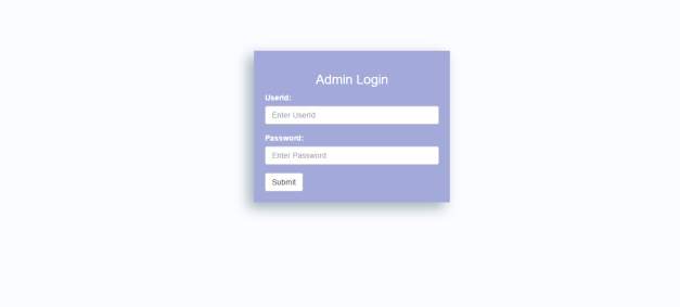 Here, Admin can login with their respective credentials.
 After admin login, this is the view page, where admin can monitor.
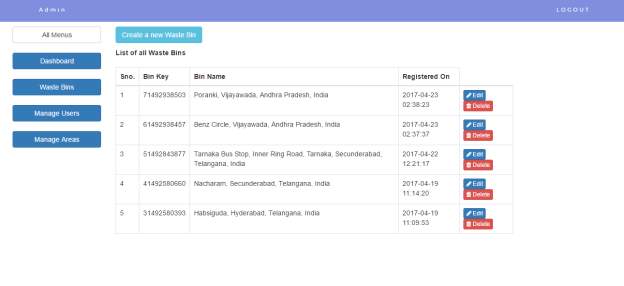
 Here, is the view of clicking Dashboard, where the number of bins w.r.t members are displayed.
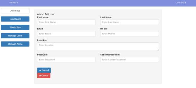 This is the view, to Create new users by filling all the deatails and then submit
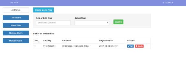 To create a new area & to manage the users w.r.t the areas.
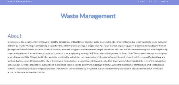 The Home page
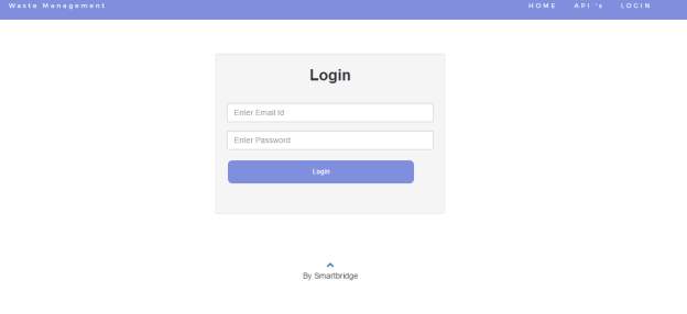 Here is the Login page, for the registered users to view the fields of bin
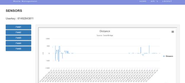 The Distance which is field1 represented via graph, for every updated values.
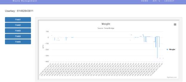 The Weight whch is field2 represented on Graph, for every updation of values.
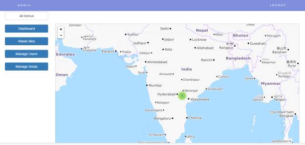
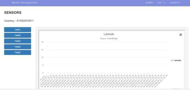 Latitude and Longitude values represented in field3 and field4
9.CONCLUSION
The objective of SWMS is to value-add existing Solid Waste Management process for waste management under local authorities, to help in decision making for waste management process, to ensure the contractors follow the work procedure, and to improved waste collection services delivery which comes under the responsibility of local authority. By manipulating geospatial technology and intelligence sensor such as ultrasonic sensors via IoT technology, SWMS application has provided the waste collection operator with a platform to work in real-time mode to improve the service by optimizing operation time and cost. SWMS application as a tools for local authority to monitor waste collection operator to ensure waste collection services is deliver accordingly as per contract. The impact of SWMS to resident, residents associations and joint management body is direct when the environment is now clean and give a healthier life. Nevertheless, the proposed SWMS requires more maintenance cost than the existing system. There is a need to make it a sustainable which is the development cost is acceptable to implement in local authority. The most important issue is how to deliver to local authority with competitive price and less maintenance cost. With the current system, the implementation only limited for apartment and condominium which the sensor device put on top of the big garbage bin inside of apartment waste chamber. In the future, small IoT gadget for waste monitoring can be develop and put inside the waste chamber in front of each terrace house and bungalow to widening the implementation to the citizen.
10. REFERENCES
[1] Enevo(2016) ONe Waste Collection for Smart Cities.
[2] Sensor, S. (2014). Dumpster Smart lling level monitoring.
[3] Libelium. (2015b). Smart Metering 2.0 Technical Guide, 4.9. Retrieved from http://www.gedigitalenergy.com/smartmetering/catalog/SGM3000_Residential.htm#sgm300 0tab5
[4] Portal Rasmi Majlis Perbandaran Sepang; (n.d.-b). Retrieved May 7, 2015, from http://www.mpsepang.gov.my/peta-daerah-sepang
[5] Portal Rasmi Pejabat Daerah / Tanah Kuala Langat Peta - Peta Daerah Kuala Langat. (n.d.). Retrieved May 7, 2015, from http://www.selangor.gov.my/kualalangat.php/pages/view/186
[6] LEA-6/NEO-6/MAX-6 Hardware Integration Manual, Docu. GPS.G6-HW-09007
[7] u-blox 6 Receiver Description Including Protocol Specification (Public version), Docu. No. GPS.G6-SW-10018
[8] u-blox 6 Receiver Description Including Protocol Specification (Confidential version), Docu. No. GPS.G6-SW-10019
[9] u-blox Package Information Guide, Docu. No GPS-X-11004
.
Latitude and Longitude values represented in field3 and field4
9.CONCLUSION
The objective of SWMS is to value-add existing Solid Waste Management process for waste management under local authorities, to help in decision making for waste management process, to ensure the contractors follow the work procedure, and to improved waste collection services delivery which comes under the responsibility of local authority. By manipulating geospatial technology and intelligence sensor such as ultrasonic sensors via IoT technology, SWMS application has provided the waste collection operator with a platform to work in real-time mode to improve the service by optimizing operation time and cost. SWMS application as a tools for local authority to monitor waste collection operator to ensure waste collection services is deliver accordingly as per contract. The impact of SWMS to resident, residents associations and joint management body is direct when the environment is now clean and give a healthier life. Nevertheless, the proposed SWMS requires more maintenance cost than the existing system. There is a need to make it a sustainable which is the development cost is acceptable to implement in local authority. The most important issue is how to deliver to local authority with competitive price and less maintenance cost. With the current system, the implementation only limited for apartment and condominium which the sensor device put on top of the big garbage bin inside of apartment waste chamber. In the future, small IoT gadget for waste monitoring can be develop and put inside the waste chamber in front of each terrace house and bungalow to widening the implementation to the citizen.
10. REFERENCES
[1] Enevo(2016) ONe Waste Collection for Smart Cities.
[2] Sensor, S. (2014). Dumpster Smart lling level monitoring.
[3] Libelium. (2015b). Smart Metering 2.0 Technical Guide, 4.9. Retrieved from http://www.gedigitalenergy.com/smartmetering/catalog/SGM3000_Residential.htm#sgm300 0tab5
[4] Portal Rasmi Majlis Perbandaran Sepang; (n.d.-b). Retrieved May 7, 2015, from http://www.mpsepang.gov.my/peta-daerah-sepang
[5] Portal Rasmi Pejabat Daerah / Tanah Kuala Langat Peta - Peta Daerah Kuala Langat. (n.d.). Retrieved May 7, 2015, from http://www.selangor.gov.my/kualalangat.php/pages/view/186
[6] LEA-6/NEO-6/MAX-6 Hardware Integration Manual, Docu. GPS.G6-HW-09007
[7] u-blox 6 Receiver Description Including Protocol Specification (Public version), Docu. No. GPS.G6-SW-10018
[8] u-blox 6 Receiver Description Including Protocol Specification (Confidential version), Docu. No. GPS.G6-SW-10019
[9] u-blox Package Information Guide, Docu. No GPS-X-11004
.
3.2.4 Operational feasibility
It quantifies as to how good the proposed system is working in solving the problem, that can take advantage of the opportunity acknowledged through scope description and how the necessities can be satisfied according to their requirements analysis phase of structure progress.
3.2.5 Schedule feasibility
If its too enlarged, the project will not succeed in completing before-hand. The inference of how much time it takes to build up, and also it can be finished in given interlude using few methods like reimbursement period. Schedule feasibility is to calculate how rational the project program is. Given our technological capability, are the project deadline levelheaded? Some projects are initiate with precise deadlines. You need to conclude whether the deadlines are obligatory or enviable. JAVA SERVER PAGES: The powerful technology that can generate web pages on server side dynamically is Java server page. The extension to servlets of java is direct in and also there is a way to isolate generation and presentation of the content. FEATURES OF JSP:- Processing:
- Portability:
- A HTML document is small and hence easy to send over the net.It is small because it does not include formatted information.
- HTML is platform independent.
- HTML tags are not case-sensitive.
- Prepared Statement- the statement is cached and then the execution path is indomitable on the database sever allowing it to be executed several times in an resourceful manner.
- Callable Statement- second hand for executing stored procedures on the database.
- Statement – the statement is sent to the database server each one and every time.
- TYPE-1
- TYPE-2
- TYPE-3
- TYPE-4
Functions:
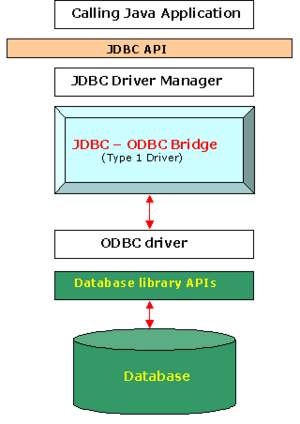
- Translates query obtained by JDBC into corresponding ODBC query, which is then handled by the ODBC driver.
- Sun provides a JDBC-ODBC Bridge driver. Sun.jdbc.odbc.JdbcDriver. This driver is native code and not Java, and is closed source.
- Client -> JDBC Driver -> ODBC Driver -> Database
- There is some overhead with the translation work to go from JDBC to ODBC.
- Almost any database for which ODBC driver is installed, can be accessed.
- A type 1 driver is easy to install.
- The driver is platform-dependent as it makes use of ODBC which is in turn depends on native libraries of the underlying operating system the JVM is running upon.
- This technology isn’t suitable for a hign-transaction environment.
- This driver is non-portable given the binding between the driver and platform.
- This drivers also don’t support the complete Java command set and are limited by the functionality of the ODBC driver.
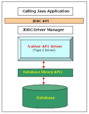
The type 2 driver is not written entirely in java as it interfaces with non-Java code that makes the final database calls. The driver is compiled for use with the particular operating system. For platform interoperability, the Type 4 driver, being a full-Java implementation, is preferred over this driver.
However the type 2 driver provides more functionality and better performance than the type 1 driver as it does not have the overhead of additional ODBC function calls.
Advantages:
- Better performance than Type 1 Driver(JDBC-ODBC Bridge)
- Provides Fastest performance than all 3 drivers as it calls native APIs( MySQL, Oracle etc.)
- The vendor client library has to be installed on the client machine.
- Cannot be used in web-based application due to the client side software needed.
- Not all databases have client side library.
- This server is platform dependent.
- This driver supports all java applications except Applets.
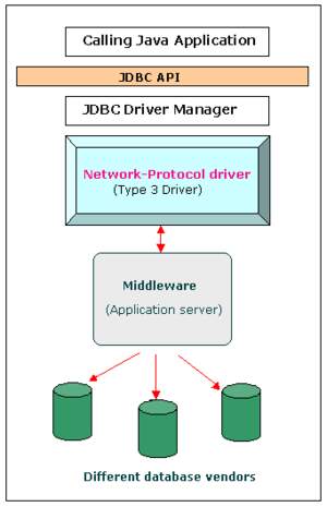
This differs from the type 4 driver in that the protocol conversion logic resides not at the client, but in the middle-tier. Like type 4 drivers, the type 3 driver is written entirely in Java. The same driver can be used for multiple databases. It depends on the number of databases the middleware has been configured to support. The type 3 driver is platform –independent as the platform-related differences are taken care by the middleware. Also, making use of the middleware provides additional advantages of security and firewall access.
Functions:
- Follows a three tier communication approach.
- Can interface to multiple databases –Not vendor specific.
- The JDBC Client driver written in Java, communicates with a middleware-net-server using a database independent protocol, and then this net server translates this request into database commands for that database.
- Thus the client driver to middleware communication is database independent.
- Client -> JDBC Driver -> Middleware-Net-Server -> Any Database.
- Since the communication between client and the middleware server is database independent, need not be changed for a new database.
- The Middleware Server(which can be a full fledged J2EE Application server) can provide typical middleware services like caching(connections, query results, and so on), load balancing, logging, auditing etc.
- Eg. For the above include jdbc driver features in Weblogic.
- Can be used in internet since there is no client side software needed.
- At client side a single driver can handle any database. (It works provided the middleware supports that database)
- Requires database-specific coding to be done in the middle tier.
- An extra layer added may result in a time-bottleneck. But typically this is overcome by providing efficient middleware services.
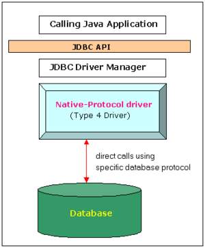
Functions:
- Type 4 drivers are entirely written in Java that communicates directly with a vendor’s database, usually through socket connections. No translation or middleware layers are required, improving performance.
- The driver converts JDBC calls into the vendor-specific database protocol so that client application can communicate directly with the database server.
- Completely implemented in Java to achieve platform independence.
- Eg: include the widely used Oracle thin driver – oracle.jdbc.driver.OracleDriver which connect to jdbc:oracle:thin URL format.
- Client -> Native Protocol JDBC Driver -> Database server
- These drivers don’t translate the requests into an intermediary format(such as ODBC ), nor do they need a middleware layer to service requests. Thus the performance may be considerably improved.
- All aspects of the application to database connection can be managed within the JVM; this can facilitate easier debugging.
- At client side, a separate driver is needed for each database.
- REGISTERING THE DRIVER:
- CONNECTING TO A DATABASE:
- PREPARING SQL STATEMENT:
- EXECUTING THE SQL STATEMENTS ON THE DATABASE:
- RETRIEVING THE RESULTS:
- CLOSING THE CONNECTION:
SYSTEM DESIGN
5.1 INPUT DESIGN The input design is the link between the information system and the user. It comprises the developing specification and procedures for data preparation and those steps are necessary to put transaction data in to a usable form for processing can be achieved by inspecting the computer to read data from a written or printed document or it can occur by having people keying the data directly into the system. The design of input focuses on controlling the amount of input required, controlling the errors, avoiding delay, avoiding extra steps and keeping the process simple. The input is designed in such a way so that it provides security and ease of use with retaining the privacy. Input Design considered the following things:- What data should be given as input?
- How the data should be arranged or coded?
- The dialog to guide the operating personnel in providing input.
- Methods for preparing input validations and steps to follow when error occur.
- Convey information about past activities, current status or projections of the
- Future.
- Signal important events, opportunities, problems, or warnings.
- Trigger an action.
- Confirm an action.
| Window |
| Origin Size |
| open() close() move() display() |
Fig: Classes
A use case is a description of set of sequence of actions that a system performs and the result is observed by an actor.
Fig: Use Cases
A node is a physical element.It exists at the runtime and represents a computational resource which has atleast some memory and also the processing capability.
Fig: Nodes
2. Behavioral things are the dynamic parts of UML models. The behavioral thing used is:
Interaction:
An interaction is a behaviour that consists a set of messages exchanged among a set of objects within a particular context to accomplish a specific purpose. It involves a number of other elements, including the behaviour of the messages and the connection between the objects
Fig: Messages
2. Relationships in the UML:
There are four kinds of relationships in the UML: • Dependency• Association• Generalization• Realization. A dependency is a semantic relationship between two things in which changing one thing affects the other thing which means both are dependant on each other. It is represented by a dotted line with an arrow at one end.
Fig: Dependencies
An association comes under structural relationship. It describes a setof links and the connection between objects. An Aggregation is a special kind of association. It represents a relationship between a whole and its parts.
Fig: Association
A generalization is a specialization-generalization relationship in which objects of specialized elements- child elements helps in substituting the generalized - parent elements one works on it.
Fig: Generalization
A realization is a relationship between classifiers. Here on classifier specifies the other works on.
Fig: Realization
4.1 UML DIAGRAMS
A diagram is a graphical presentation of a set of elements.It represents a connected graph. UML consists of nine such diagrams. Unified Modeling Language (UML) is probably the most widely used notation for object-oriented methods. UML is a standar language for writing Software Blueprints.
The UML may be used to visualize, specify, construct and document the artifacts. A modeling language focuses on the physical and conceptual representation of a system. Modeling is the process of designing of the software applications before coding. Modeling plays an essential part in large,medium and small projects as well.A project without a good model cannot assure the success.It ensures the project's success and helps in correct and complete business functionality. Modeling should be done according to the needs of the client or end user.
The UML diagrams are as follows:
Class Diagram: The class diagram is used to define a detailed design of the system in which the actors are classified into set of interconnected classes. Each class provides a set of certain functionalities which can be termed as methods of the classes. Each class is identified to be unique as they have a different set of attributes.
6. SOFTWARE ENVIRONMENT
6.1 ARDUINO
Arduino is an open-source prototyping platform.It acts as an interface between hardware and software. The Arduino Integrated Development Environment(IDE) or and Arduino Software contains a text editor for writing code, a message area referred to as a Serial Monitor, a system console where in the warnings, errors and the compilation details are shown, a toolbar with buttons for common functions and a series of menus. It connects to the Arduino and hardware to upload programs and communicate with them.
Programs written using Arduino Software are referred to as sketches. These sketches are written in the text editor and are saved with the file extension .ino. The editor involves a feature for cutting/pasting and for searching/replacing text. The message area gives feedback while saving,compiling and exporting. It also displays the errors. The system console displays text output by the Arduino Software (IDE), including complete error messages and other information. The bottom right-hand corner of the window displays the configured board and serial port. The toolbar buttons allow you to verify and upload programs, add required libraries,create and save sketches, and open the serial monitor.
The following are the buttons displayed on the editor
 |
Verify Checks your code for errors compiling it. |
 |
Upload Compiles your code and uploads it to the configured board. See uploading below for details. Note: If you are using an external programmer with your board, you can hold down the "shift" key on your computer when using this icon. The text will change to "Upload using Programmer" |
 |
New Creates a new sketch. |
 |
Open Presents a menu of all the sketches in your sketchbook. Clicking one will open it within the current window overwriting its content. Note: due to a bug in Java, this menu doesn't scroll; if you need to open a sketch late in the list, use the File | Sketchbook menu instead. |
 |
Save Saves your sketch. |
 |
Serial Monitor Opens the serial monitor. |
Here, Admin can login with their respective credentials.
After admin login, this is the view page, where admin can monitor.
Here, is the view of clicking Dashboard, where the number of bins w.r.t members are displayed.
This is the view, to Create new users by filling all the deatails and then submit
To create a new area & to manage the users w.r.t the areas.
The Home page
Here is the Login page, for the registered users to view the fields of bin
The Distance which is field1 represented via graph, for every updated values.
The Weight whch is field2 represented on Graph, for every updation of values.
Latitude and Longitude values represented in field3 and field4
9.CONCLUSION
The objective of SWMS is to value-add existing Solid Waste Management process for waste management under local authorities, to help in decision making for waste management process, to ensure the contractors follow the work procedure, and to improved waste collection services delivery which comes under the responsibility of local authority. By manipulating geospatial technology and intelligence sensor such as ultrasonic sensors via IoT technology, SWMS application has provided the waste collection operator with a platform to work in real-time mode to improve the service by optimizing operation time and cost. SWMS application as a tools for local authority to monitor waste collection operator to ensure waste collection services is deliver accordingly as per contract. The impact of SWMS to resident, residents associations and joint management body is direct when the environment is now clean and give a healthier life. Nevertheless, the proposed SWMS requires more maintenance cost than the existing system. There is a need to make it a sustainable which is the development cost is acceptable to implement in local authority. The most important issue is how to deliver to local authority with competitive price and less maintenance cost. With the current system, the implementation only limited for apartment and condominium which the sensor device put on top of the big garbage bin inside of apartment waste chamber. In the future, small IoT gadget for waste monitoring can be develop and put inside the waste chamber in front of each terrace house and bungalow to widening the implementation to the citizen.
10. REFERENCES
[1] Enevo(2016) ONe Waste Collection for Smart Cities.
[2] Sensor, S. (2014). Dumpster Smart lling level monitoring.
[3] Libelium. (2015b). Smart Metering 2.0 Technical Guide, 4.9. Retrieved from http://www.gedigitalenergy.com/smartmetering/catalog/SGM3000_Residential.htm#sgm300 0tab5
[4] Portal Rasmi Majlis Perbandaran Sepang; (n.d.-b). Retrieved May 7, 2015, from http://www.mpsepang.gov.my/peta-daerah-sepang
[5] Portal Rasmi Pejabat Daerah / Tanah Kuala Langat Peta - Peta Daerah Kuala Langat. (n.d.). Retrieved May 7, 2015, from http://www.selangor.gov.my/kualalangat.php/pages/view/186
[6] LEA-6/NEO-6/MAX-6 Hardware Integration Manual, Docu. GPS.G6-HW-09007
[7] u-blox 6 Receiver Description Including Protocol Specification (Public version), Docu. No. GPS.G6-SW-10018
[8] u-blox 6 Receiver Description Including Protocol Specification (Confidential version), Docu. No. GPS.G6-SW-10019
[9] u-blox Package Information Guide, Docu. No GPS-X-11004
.
Cite This Work
To export a reference to this article please select a referencing stye below:
Reference Copied to Clipboard.
Reference Copied to Clipboard.
Reference Copied to Clipboard.
Reference Copied to Clipboard.
Reference Copied to Clipboard.
Reference Copied to Clipboard.
Reference Copied to Clipboard.
Related Services
View all


Related Content
All TagsContent relating to: "Environmental Studies"
Environmental studies is a broad field of study that combines scientific principles, economics, humanities and social science in the study of human interactions with the environment with the aim of addressing complex environmental issues.
Related Articles

DMCA / Removal Request
If you are the original writer of this dissertation and no longer wish to have your work published on the UKDiss.com website then please: