Assessing Silica Particles in Tyre Formulations
Info: 11259 words (45 pages) Dissertation
Published: 16th Dec 2019
Tagged: EngineeringSciences
- Table of Contents
2.1 Historical background to recycling of rubbers
2.2 Aims and objectives of project
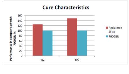
3.5 Reclaimed silica mechanical properties
4.4.1 Transmission electron microscopy
4.4.2 Scanning electron microscopy
4.5.2 Fourier transform infrared spectrometer
5.1.1 Scanning electron microscopy
5.1.2 Transmission electron microscopy
6.1.1 Fourier transform infrared spectrometer
2 Introduction
The rubber industry is one in which is dominated by the manufacture of tyres predominantly used for transport for passenger, goods vehicle and the aerospace industry. Annually, 1.5 billion tyres are manufactured globally that carries its own concerns regarding the disposal of end-of-life tyres (ELT’s) and the raw ingredients required to fulfil the high demands. ELTs were frequently disposed of in tyre landfills awaiting treatment plans with a small percentage reused for its original purpose by the means of re-treading (replacing worn tread), while others can be utilised as they are or shredded and used for varying applications such as construction bales, coastal defence, sport surfaces, paving blocks, etc. Tyres are a complex composite structure consisting of a mixture of different rubber formulations along with textiles and metallic support. The majority of the composition is synthetic/natural rubbers followed by reinforcing fillers: Carbon black and silica; these said fillers are utilised to enhance the tyres physical features such as abrasion, rolling resistance, stiffness, tear etc. As regions of the tyre require different properties, the combination of silica and carbon black vary from section to section making it more difficult reclaim high yields as both fillers are reclaimable with reclaimed carbon black current commercially available. The optimum process is to shred the tread for silica recovery (possibly the sidewalls also in the near future) and recover the blacks from the rest of the tyre
Rolling resistance, traction and wear resistance are the key features for tyres; this is known as the magic triangle shown in Figure 1. Sidewall can affect the handling of the vehicle and need to be stiff enough to give good response time (does not flex from side to side when steering) and hold the vehicle weight but flexible enough to allow the tread to be in full contact with the road when corning. The bead region at the edge of tyre is the only region of the tyre in contact with the wheel of the vehicle and prohibits the tyre from taking off due to centrifugal forces when rotating. The key region of tyre is the tread which converts the tractable force of the motor by gripping the road, this is the only part of the vehicle that is in contact with the road and the formulation of the compound can be altered to give a vast amount of properties such as good wear resistance, wet grip, dry grip, economical, low noise levels, etc. fulfilling each point of the triangle is not yet possible so the correct balance is necessary for the conditions used.
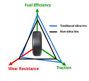
Approximately 30% of fuel consumed by the vehicle engine is to overcome the resistance of the tyre known as rolling resistance. In order to reduce impact apposed on the environment due to the additional combustion of fossil fuels, US and European regulations such as the regulation (EC) No 661/2009 of the European Parliament and of the Council of 13 July 2009 concerning type-approval requirements for the general safety of motor vehicles, their trailers and systems, components and separate technical units have stated improvements on rolling resistance. With the use of silica technology within the matrix (first used by Michelin), this is now possible hence the drive for reclaiming this material from waste tyres.
Carbon black first introduced in the 1900s was used to replace high loadings of zinc oxide that is still used today but in much lower loading for vulcanisation. The introduction of carbon black lead to improved wear resistance and wet grip but for the past decade silica loadings have increased due to strict regulations in regards to saving fuel and cutting down on greenhouse gasses. Carbon black is seen to be more effective as reinforcement filler than untreated silica (without a coupling agent) due to the lack of bonding between silica and rubber. Past reports by ARTIS has shown the increase of filler-filler reaction without the presents of a coupling agent using DMA data in comparison to carbon black. For this reason, tyre formations include a coupling agent if silica is present to encourage filler-polymer interactions.
Filler-polymer interactions lead to better reinforcing properties of the compound and one way of increasing this is using high surface area fillers. The surface area of reinforcing filler gives a representation of the number of sites available for interactions with more interactions equating to better reinforcing abilities, however the sites may not be active depending on its condition. Homogeneous mixture of filler within the matrix is of great importance to avoid defects and stress concertation points that will affect the mechanical properties of the compound which can be an issue with high surface are fillers. Using high surface area fillers is more difficult to disperse during the mixing cycle due to increased reactions that lead to higher shear forces and higher energy bills.
2.1 Historical background to recycling of rubbers
The recycling of rubber articles goes as far as the rubber industry itself with approx. half of the rubber products manufactured recycled in the 1900s. The recycling of natural rubber continued to increase in the 1900s, especially with the price of natural rubber closely match of that with silver. During the 1960s, the recycling of rubber products dropped to approx. 20% due to the introduction of steel reinforcement in tyres that dominated the rubber industry. The additional metallic material made the process of recycling the composite much more difficult which is covered in more detail later on. From 1900s to early 1990s, the percentage of recycled material utilised in the rubber industry dropped from approx. 50% to 2%, however, with the drive behind recycling today regarding reducing landfills, protecting resources and reducing greenhouse gasses the percentage of recycled rubbers has increased once again.
2.2 Aims and objectives of project
The aims and objective of this given project is to compare and contrast the physical and chemical features of virgin silica and reclaimed silica which is achieved by going through an oxidation process during heating. The optimum point in respect to temperature and duration is yet to be identified by ARTIS therefore this project purely analysis the reclaimed physical and chemical features in order to give an indication of its optimum processing conditions. In order to study this, scanning electron microscopy equipped with X-ray analysis and transmission electron microscopy are to be utilised to gather an understanding of any physical characteristics between the reclaimed and virgin silica’s such as state of aggregation. In addition, the any chemical changes that may have occurred is analysed with the use of Fourier transform infrared spectroscopy followed by X-ray analyser of the SEM to analysis any compositional change.
3 Literature review
3.1 Tyre recycling issue
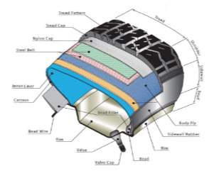 Modern passenger tyres can be very difficult to recycle due to layers of varying materials such as textiles, metals and rubbers. The compound formulation itself is not the same formulation used throughout the tyre but varies depending on the region and what properties that typical region requires, for example the tread is higher in silica filler for a premium tyre in comparison with carbon black (CB) and vice versa for the carcass. According to introduction to tyre recycling 2013, tyres consist of 40 – 48% Natural and synthetic rubbers, 22 – 27% Silica or/and carbon black fillers, 5 – 25% Reinforcing material (metals and textiles), 0 – 8% Facilitators (waxes, processing aids, plasticisers, anti-oxidants, etc.). Figure 2 shows a typical schematic of a modern passenger road tyre; each region of the tyre is engineered and thoroughly tested to give the required properties for its intended purpose.
3.2 Waste management of end-of-life tyres
Waste is termed as something that is no longer fit or acceptable to fulfil its duties. One way of preserving the planets natural resources is to recycle waste products such as tyres and other products like plastic bottles. The recycling of tyres is something that was very popular initially but due to new complicated structures it has become more difficult and costly to recycle as discussed in previous section. Thankfully, due to new regulations and the need for the raw materials, the recycling of tyres has picked up once again. This section will predominantly look at the possible stages for end of like tyres.
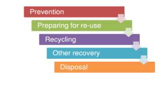
The number one method of reducing waste according to European directives and UK regulations is preventing it in the first place according to the hierarchy shown in Figure 3. The egulations are not only intended toward tyre waste but any form of waste in general. While preventing tyre waste is impossible, prolonging its life spams is certainly achievable by using advance compounds to improve wear, maintaining vehicle (wheels are aligned so the whole tread is utilised rather than a small portion), slower cornering or even by using less material in the tyre initially so less is disposed of at the end of its life and a good example of this is the Dunlop sport maxx RT range.
3.2.1 Landfill of end-of-life tyres
Tyre landfills were an increasing problem worldwide and were far worse in the US. According to Recycle Nation, a staggering 300 million tyres were disposed of annually throughout the sates awaiting treatment plans. Not only do tyre landfills require a large amount of space that could otherwise be utilised but they also expose harm to the environment, especially when burnt. Igniting a pile of tyres may be difficult, however once ignited they are very hard to extinguish especially with large voids in the pile fuelling the fire due to the natural shape of tyres. Fumes given off from tyres are both very harmful to people and especially the environment that includes sulphur oxide and carbon dioxide.
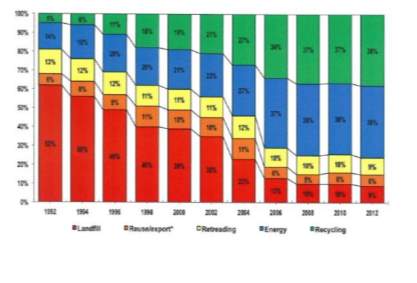 The EU recycling societies target goal is 0% landfilling and Figure 4 shows the extensive increase in recycling during the years 1992 – 2012 since this plan was put into action, extracted from ‘the European tyre recycling association, the only European organisation devoted exclusivity to tyre and rubber recycling’ from the 24 EU countries by the end of 2012. While the main reason behind the deduction in land filling is initiated by regulations, it has also decreased due to some waste being utilised as fuel as well as reclaiming the carbon black filler.
3.2.2 Re-use of end-of-life tyres for its original application
The next stage of the hierarchy is to re-use the tyre for its intended original application and the main route taken is re-treading of the original tyre. Re-treading is the process of removing the old tread and curing another layer on thereby saving the whole carcass of the tyre with very little waste of the original tyre. The majority of the silica content in located at the tread and sidewalls so in regards to reclaiming silica, it is advantageous to only remove the tread that can then be reclaimed. Re-treaded tyres are deemed to be the green approach and cost effect but can be dangerous if the process is not done correctly. There are reports of garages simply cutting into the carcass to construct the shape of the tread as opposed to following regulations and applying a new tread. This opposes obvious dangers: (a) tyre thickness is considerably lower and (b) the rubber formulation in the carcass is not suitable to be used as the point of contact on the road. Not only does re-treading address the problem with disposal of tyres but also reduced the amount of energy used in comparison to a new tyre; a new tyre uses approx. twice as much energy compared to re-treading. Cold or hot curing are the methods for re-treading once X-ray inspections confirm condition of carcass is safe for re-use. If passengers tyres are re-treated using the cold cure method, the tyre can be re-treaded and infinite amount of times, however, if hot cured, it can only be re-treaded once due to increased temperatures. Cold and hot curing occurs at 100°C and up to 180°C respectively. Truck tyres can also be re-treaded similar to passenger tyres but not as often as passenger tyres due to more stringent regulations regarding the condition of the carcass.
3.2.3 Recycle of end-of-life tyres
Whilst re-treading tyres is an excellent approach to re-use the majority of the tyre for its intended purpose, they are not always accepted due to its reduced quality as opposed to its new product in certain industries such as aerospace or motorsports but these can still be used for other applications along with other reject carcass that cannot be re-treaded. As rubbers are great materials for energy and vibration absorbing, they are often shredded or kept in their natural form and used as coastal defence, playground paving, sport surfaces, noise barriers and many more.
3.2.4 Other end-of-life tyre recovery methods
Other forms of recovery include energy recover from the high calorific value oils during pyrolysis or recovering any of the initial ingredients such as the fillers. Extensive work has been conducted in the past by ARTIS and many other Arthurs such as regarding the reclamation of carbon black that is now commercial available to purchase. Reclaimed carbon black is obtained through a pyrolysis process where the waste rubber is heated in inset atmospheres that yield solid chars, pyrolysis oils and gasses. ARTIS have conducted project analysing reclaimed carbon black and some of the results are discussed in this section.
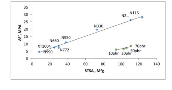

Figure 5 shows relationship between surface area values (STSA) and network efficiency (ΔE’) of commercial virgin carbon blacks and generated pyrolysis blacks from past work from ARTIS. There’s a linear relationship in that the higher the virgin commercial fillers surface area, the higher the network efficiency, which is expected due to increased surface activity. The network efficiency of the reclaimed blacks falls significantly below the virgin blacks; measured STSA value are as high as
N234 grade but network efficiency value of a low surface area grade black (N772). One of the reasons contributing towards this low network efficiency was found to be dispersion due to poorly milled rCB; while dispersion is not the only reason to poor network efficiency, it certainly contributes towards it.
Another reason is carbonaceous residue that coats the reclaimed filler particles covering the graphitic crystallite ends of the black causing reduced surface activity within the rubber matrix; carbonaceous residue does not only effect surface chemistry but also dispersion as aggregates are ‘fussed’ together during pyrolysis stage creating large agglomerates. These large agglomerates are too strong to break down during the mixing cycle thereby creating stress concentration points within the cured rubber. Efficient milling of the rCB is always required to breakdown the large agglomerates to small aggregates that are more dispersible. However, the cryogenic milling used by ARTIS was not enough to break down the agglomerates creating stress concertation within the rubbers
3.3 Reinforcing fillers in tyres
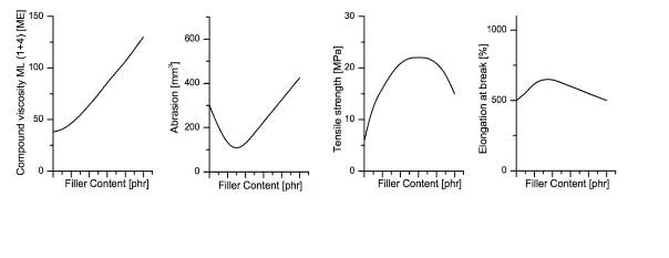
Synthetic and natural rubbers used in tyres are always mixed with reinforcing fillers to enhance their properties as they are deemed to be too weak to be utilised for such application. Figure 6 shows how reinforcing fillers can improve the rubbers mechanical properties; Improved mechanical properties with the use of reinforcing fillers also has disadvantages disadvantages including such as increased viscosity.
Both silica and carbon black fillers have an aggregate structure in which the cavities are filled during mixing when the viscosity of the mix is viscous enough to flow and the ram is lower, the rubber penetrates the air pockets. Once all the air pockets are filled, the rubber is restricted the high shear forces causes the bonds to break down and disperse within the rubber matrix creating a homogenous mix. Predominantly carbon black was the main reinforcing filler utilised but today the drive for silica is ever more increasing due to new regulations regarding fuel savings as silica is known to reduce rolling resistance. Using silica is not as easy as adding it to a mix as it has different polarity to the rubbers with minimal reinforcing abilities therefore a coupling agent is required to coat the silica surface and remove the polarity.
3.3.1 Use of carbon black in tyres
The value of tan delta obtained from dynamic mechanical analysis testing is the standard of measuring rolling resistance shown in figure 2 that compared a carbon black filled only compound and silica filled. Figure 1 shows that the silica filled compound remains below the carbon filled compound during the majority of the test thereby equating to reducing rolling resistance.
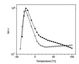
Figure 9: Tan delta of virgin vs carbon black filled compound
3.3.2 Used of silica in tyres
Silica has been used for many years in rubber artefacts including shoe soles, rubbers hoses and belt as well tyres. Silica as a reinforcing material in respect to elastomer materials comes in the form of fumed silica with particle diameter of 5-20nm, precipitated: 10-30nmm that are highly reinforcing or precipitated silica 40nm that is semi-reinforcing.
 Fumed silica’s are ranked too expensive and for that reason are rarely used in tyres formulations. The white precipitated silica powders used in this project is obtained via the reaction of sodium silicate and sulphuric or carbonic acid. The reinforcement capability of a specific reinforcement, whether its carbon black or silica can easily be predicted by its given surface area making it the most important factor (more surface area = more active sites = more reinforcement). Silica In general possesses a higher surface area than carbon black making the white filler the ideal candidate for reinforcement but they are more costly to process due to the high temperatures required for salinisation to occur during mixing. Carbon black is one that is easily dispersed (depending on the surface area) without any additional modifications to the surface but the same cannot be said for silica; from past work by ARTIS and literature, it was concluded that when silica is replaced with carbon black or combined with, the filler is noticeably more difficult to disperse during the mixing process to obtain a homogenous mix shown in Figure 7.
The inorganics silica surface consists of silanol groups (Si-OH) that can come in two structures shown in Figure 8: germinated or isolated but can also form hydrogen bonds. Silica exhibits significantly reduced mechanical properties if these silanos groups are left untreated when compared to a carbon black filled compound. Untreated silanol groups are not capable of bonding to organic elastomers to form the polymer-filler interactions and instead bond with themselves to form filler-filler interactions; to bypass this, coupling agents are added discussed in the following paragraph. Reinforcing fillers like carbon black increase the cure rate of a rubber compounds significantly and to address this issues, accelerators are added to speed up the cure rate. The silica surfaces are polar and are easily wetted and these silanol groups can react with the accelerators such as TBBS making the accelerator ineffective thereby slowing the cure rate even further. Silica filled rubber compounds usually have 2-4phrs polyethylene glycol (PEG) that is added to prevent the silica filler from absorbing curatives and affecting the cure rate otherwise an increase in sulphur levels or faster accelerator such CBS can also be used to increase cure rate if glycol is absent. Having a short cure time is desirable for a rubber compound in industry to maximise profits and reduce drawbacks such as heating costs. In addition, the isolated or germinated silanols will often form hydrogen bonds otherwise known as filler-filler interactions reducing its reinforcing capabilities
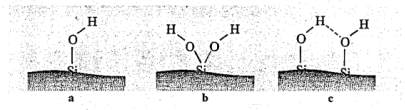
Figure 8: silanol structures (a) isolated; (b) germinated (c) associated with
each other via hydrogen bonding
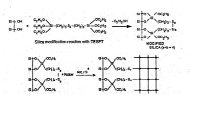 For silica to become a desirable reinforcing, surface modifications of the white silica powder are necessary and one in which that is often used in the tyre industry for tread formulations are coupling agents, often triethoxysilylpropyl- tetrasulphane (TESPT) that enhances the rubbers mechanical properties. The TESPT is added during the mixing stage in which the silanol groups react with the silica shown in Figure 9; the tetrasulphane group of the coupling agent is broken with addition of heat input but can also be influenced with some curing systems such as sulphur and these broken bonds in then react with the rubber matrix to create the desired filler-polymer interactions necessary to form a highly reinforced matrix.
3.4 Rolling resistance of tyres
Due to the action of side walls bending and the tread flattening due to the weight of the car and road surface during operation of the tyre, the tyre is constantly using energy, this is otherwise known as rolling resistance. New regulations have been induced for some time that require more eco-friendly green tyres to save consumers on fuel and reduce the amount of greenhouse gasses emitted to the atmosphere. Past papers and work by ARTIS has shown that with the use of silica in both the sidewalls and tread reduces rolling resistance thereby improving fuel economy of the vehicle. The significances of reducing rolling resistance are that abrasion properties will drop due to a reduction in carbon black that was demonstrated in the magic triangle in Figure 1. Table 1 shows some of the top tyre manufactures along with their fuel economy rating, silica and carbon black content with a clear coloration that silica improves fuel economy of the vehicle. The Dunlop, Michelin and good year tyres have the highest fuel efficiency rating of B that also showed the highest silica content with more than 30% while the Sunny tread showed the lowest fuel efficiency and silica content.
| Tyre Description | Fuel Efficiency | Silica, % | Carbon Black, % |
| Dunlop Bluresponse Tread | B | 33.1 | 4.3 |
| Avon ZV5 Tread | C | 28.4 | 7.8 |
| Pirelli Cinturato P7 Tread | C | 29.9 | 2.5 |
| Michelin Energy Tread | B | 31.9 | 2.6 |
| Goodyear Efficient Grip Tread | B | 32.2 | 4.8 |
| Bridgestone Turanza Tread | C | 32.3 | 3.6 |
| Nexen N blue ECO Tread | C | 26.3 | 9.2 |
| Sunny Harmonic Tread | E | 24 | 9.7 |
Table 1: Commercially available tyres tread filler content and fuel economy ratings
3.5 Mechanical properties of silica-filler rubber
Reclamation of silica is something that has not been covered in literature whereas carbon black has extensively been covered due to its commercial availability. The possibility for using reclaimed silica has big potential from past laboratory work by ARTIS that has shown improved properties compared to the reclamation process of its neighboured filler: carbon black. If in the future the reclamation process of silica was commercially available along with the currently available commercial carbon black, only one of the fillers can be reclaimed from a given feedstock so in order ti achieve the maximum amount yield, the tread and sidewalls will need to be striped to recover the silica whereas the rest of the tyre can undergo a pyrolysis process to recover the carbon black. Silica content is much higher in tread compared to any other region of the tyre followed by the sidewalls to increase stiffness. This section mainly analyses past work conduced on reclaimed silica’s and how these have affected the mechanical properties of the compound.
The surface area of the reclaimed silica indicates the fillers potential reinforcing capabilities and therefore the most important parameter to consider as mentioned before. Increasing network efficiency increases the materials reinforcing potential within a rubber compound and one way of achieving this to use higher surface area fillers to increase network efficiency. Nitrogen surface area testing is used to estimate both the external surface area and porosity. In order to gain an accurate reading, the samples most be free of any impurities so the first sage is cleaning: samples are loaded into cells that are then heated under a vacuum to remove any oil/moisture present. Cells are then submerged into a bath of liquid nitrogen to keep temperature constant as adsorbates (nitrogen gas) are released into the cell at stages to which the gas molecules are absorbed by the solid and cover a thin layer of the solid. BET theory can then estimate the number of molecules required to cover the absorbents surface and additional layers are added to which in turn can also estimate pore size. From past ARTIS experiments it can be seen that reclaimed silica surface area values are reduced by approx. 12%. The reductions in surface area are partly due to the inorganic compound of zinc oxide from the original compound formulation.
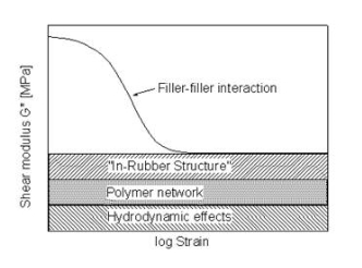
Dynamic mechanical analysis strain sweep gives an indication of the network efficiency and filler-filler interactions of a specific compound can be determined. Figure 10 compares the strain sweep data of the virgin and reclaimed Evonik silica ULTRASIL® 7000GR. Both virgin and reclaimed silica initial have high elastic modulus which then drops at a steep gradient as strain increases, otherwise known as the Payne effect. The non-linearity of rubber compounds dynamic modulus vs strain as filler loading increases has widely been covered by a number of investigators in 1954 but was later announced by A. R. Payne explaining the phenomena of this non-linearity known as the ‘Payne effect’. The Payne effect is directly related to the dynamic properties of a cured rubber and is the measure of the breakdown of a compounds viscoelastic properties; this is of great importance within the tyre industry as tyres are faced with dynamic stresses throughout it lifespan. During the stain sweep tests, sinusoidal deformation is applied to each compound as a constant temperature and the modulus is recorded as strain increases. As the strain increases, the filler-filler interactions are broken with the weak van der walls bonds of carbon black initially followed by hydrogen bonds of the silica. As strain continues to increase, all filler-filler bonds are broken leaving behind filler-polymer interaction. Network efficiency of a compound is simply the difference in modulus between the filler-filler and the polymer-filler interaction (ΔE’ = E’0 – E’).
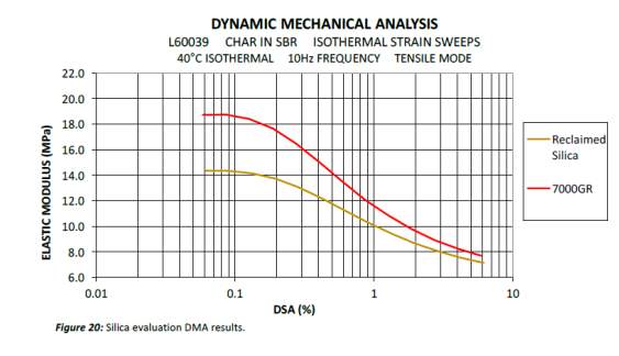
The virgin silica has the highest modulus to start with and drops with a steep gradient as strain continuous to increase. The virgin silica elastic modulus remained higher to the reclaimed silica throughout the test indicated more there were more silica-silica interactions in comparison to the reclaimed silica. The network efficiency gives an indication on the amount of cross-links that can be affected both by dispersion and surface activity: the higher the number of active sites and the more homogenous the mix the higher network efficiency Using the network efficiency equation ΔE’ = E’0 – E’, the network efficacies were calculated to be 11.05 and 7.2 for the virgin and reclaimed silica respectively. The virgin silica shown the he DMA data is not sililiansed thereby more filler-filler interaction are present hence why the difference between max elastic modulus of the virgin and reclaimed silica is higher in comparison to the differenced at the lowest elastic modulus points. Another factor that contributes to the lower network efficiency is due to the fact that the reclaimed silica include all inorganic compounds including approx. 5% zinc oxide.
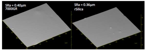
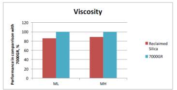
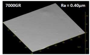
As mentioned before, dispersion is a key factor that effect the mechanical properties of the compound as less dispeared particles equates to poor mechanical properties. Past ARTIS test show that dispersion is improved with the use of reclaimed silica indicated by the SRa values shown in Figure 1. The reduced surface area mentioned before is likely to be contributing to the improved dispersion as there fewer interactions with the silianol groups of the silica during mixing therefore improve dispersion; this backed up with the viscosity of the two compouds shonw in figure 1 that shows viscosity is reduced in the reclaimed silica due to redcued interactions.
4 Experimental
4.1 Materials
All material utilised in the project was prepared off-site by ARTIS using the following procedures with the model tread formulation used in this study is shown in Table 1. The SBR in the formulation has good abrasion and traction properties, N375 is the carbon black 30nm filler, silica is the highly dispersible white filler with very good reinforcing properties, good tensile, tear and chunking, zinc oxide used as an activator for cross linking, wax, 6PPD and TMQ used as ant-oxidants/ozonant, PEG4000 prohibits silica absorbing curatives, stearic acid used as activator, siliane to enhance silica-polymer interactions, TBBS is a delay accelerator and sulphur used as crosslinking agent. Initial feedstock compounds in Table 1 were mixed using 1600cc branbury set at 40°C, 60rpm and cut into ≤6mm crumbs for oxidation heat treatment.
| Ingredients, phr | Feedstock |
| Oil extended SBR | 137.5 |
| N375 carbon black | 10.00 |
| Utrasil 7000GR | 70.00 |
| Zinc Oxide | 1.3 |
| Wax | 1.5 |
| 6PPD | 1.5 |
| TMQ | 1.00 |
| PEG 4000 | 2.00 |
| Stearic Acid | 1.00 |
| Silane couple agent | 6.00 |
| TBBS | 1.50 |
| Sulphur | 1.50 |
4.2 Recycling of silica from end-of-life tyres process
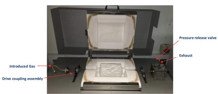 Equipment used was a Carbolite laboratory scale rotary furnace HTR 11/150, which is capable of reaching elevated temperatures of 1100°C degrees using an electric heated box furnace shown in Figure 5. The furnace consists of a fussed silica vessel that has a 950g sample capacity suspended over the heated box on top of gear assembly line that is capable of osculating the vessel 1-8 cycles per minutes through an angle of 315°. The introduced gas enters the air-tight vessel from the left and exits the systems at the exhaust towards the right; the exhaust gas runs through two pyrolysis oil collection points along with a toluene trap at the end before the exhaust fumes are vented through extraction. All reclaimed batches undergo a heat treatment process condition of 500-800°C for 1.5 – 4 hrs with air rate of approx. 3L/min. For this study only the reclaimed silica’s were analysed so oils and gasses were disposed of.
Past ARTIS reports that are discussed in the literature review show that reclaim mechanical properties different from the virgin materials therefore this project analysis the same compound before and after treatment to see if chemistry or physical features have altered in any way. The same composition rubber from the same batch is proceed at 500°C, 650°C and 800°C until the while colour is achieved. Please refer to table below for sample references that with be used through the report.
| ID | Discription |
| Sample 1 | Virgin Evonik VN3 GR silica |
| Sample 2 | Virgin Evonik 7000 GR silica |
| Sample 3 | Reclaimed Evonik 7000 GR silica at 500°C |
| Sample 4 | Reclaimed Evonik 7000 GR silica at 650°C |
| Sample 5 | Reclaimed Evonik 7000 GR silica at 800°C |
4.3 Physical analysis of the silica powders
4.3.1 Transmission electron microscopy of the recover silica powders
Transmission electron microstructure (TEM) was used to see if any for of agglomeration was formed during processed and how the agglomerated differet in respect to their treated temperatures. During the transmission electron process, electron is passed through a very thin specicmen that has been prepared that essentially then forms a shadow of the microstructure. This image is then magnified and processed on the screen for analyse. Solid materials such as silica absorbed electrons but in this case we need the electrons to pass through thereby a very thin layer is required. Approximately 0.5g of each sample was mixed with a non aquase solution since silica is hydrophilic (loves water) and placed into an ultrasonic bath in order to disperse fine partices withing the mix to be analysed. A drop of the solution was then placed on copper grid using a blah and left over for 48hours prior to entering the TEM vacuum chamber.
4.3.2 Scanning electron microscopy of the silica powders
Scanning Electron Microscopy also known as SEM is used to examine the surface of materials, find the characteristics of the material and what elements are present in the material via use energy dispersive X-ray (EDX). The SEM machine can produce images of high magnifications due to their small wave lengths which can be adjusted. Similar to transmission electron, electrons are emitted from an electron gun but rather than passing through this time, they reflected back to a detector for analysis. Scanning electron microscopy is something that is often uatlied in labotories as it allows the used to examine the partiles under high magnication but it is also a very easy and efficient process, depending on material being examined. The fine silica powders are collected on a spoon, taking car not to crush the partiles and placed on on a stub of metal with adhesive. The silica surfaces need to be conductive so a very thin layer of metallic coating in the form of gold is very applied to the samples via the sputtering effect.
4.4 Chemical analysis of the silica powders
4.4.1 Analysis of the composition from silica powders using SEM equipped with X-ray analysis
When the SEM was first used the X-rays were ignored until they discovered that it gives a lot of information about the materials composition in the 1950s and this can only be done when there is enough energy from the electrons. Two things can be found by the X-rays, one is what elements are present in the material and two is how much of the element is in the specimen. For the X-ray detector the protons are measured rather than the current and this is because the secondary electrons can knock out electrons of an atom and replace them which affect the protons.
4.4.2 Fourier transform infrared spectrometer of the silica powders
Fourier transform infrared spectrometer otherwise known as FT-IR is wdiely used technique in laboratory often for material identificantion and finger printing of almost any material. Infra-red radtion is passed through a very thin sample which in turn causes vibration of the atoms of the sample. The radiation that absorbed by thee material is trasnmited through the sample on to the detector for anyalysis. The specterum procued give the amount of radition absorbed and transmited that can be used for fingerprinting. In this case, the virgin material is taken as the benchmark to compare with the other reclaimed silica’s to examine any difference that may appear. The as received silica powders are grinded in a manual grinder with KBr (Potassium Bromide, for IR Spectroscopy) for five minutes to achive a homogenous combination of the two pwoders. The prepared powder are then poured into a mould and pressed using a hydraulic press to obtrain a thin disc of 5mm in radius and 1mm thickness. The disc is then placed inte sample holder and infra-red radition is allowed to transmit through the semi-tranparant disc.
5 Results part 1
5.1 Physical analysis
5.1.1 Scanning electron microscopy
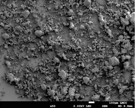
Figure 16: Sample 1 virgin Evonik ULTRASIL® VN3 GR SEM image x50 magnification
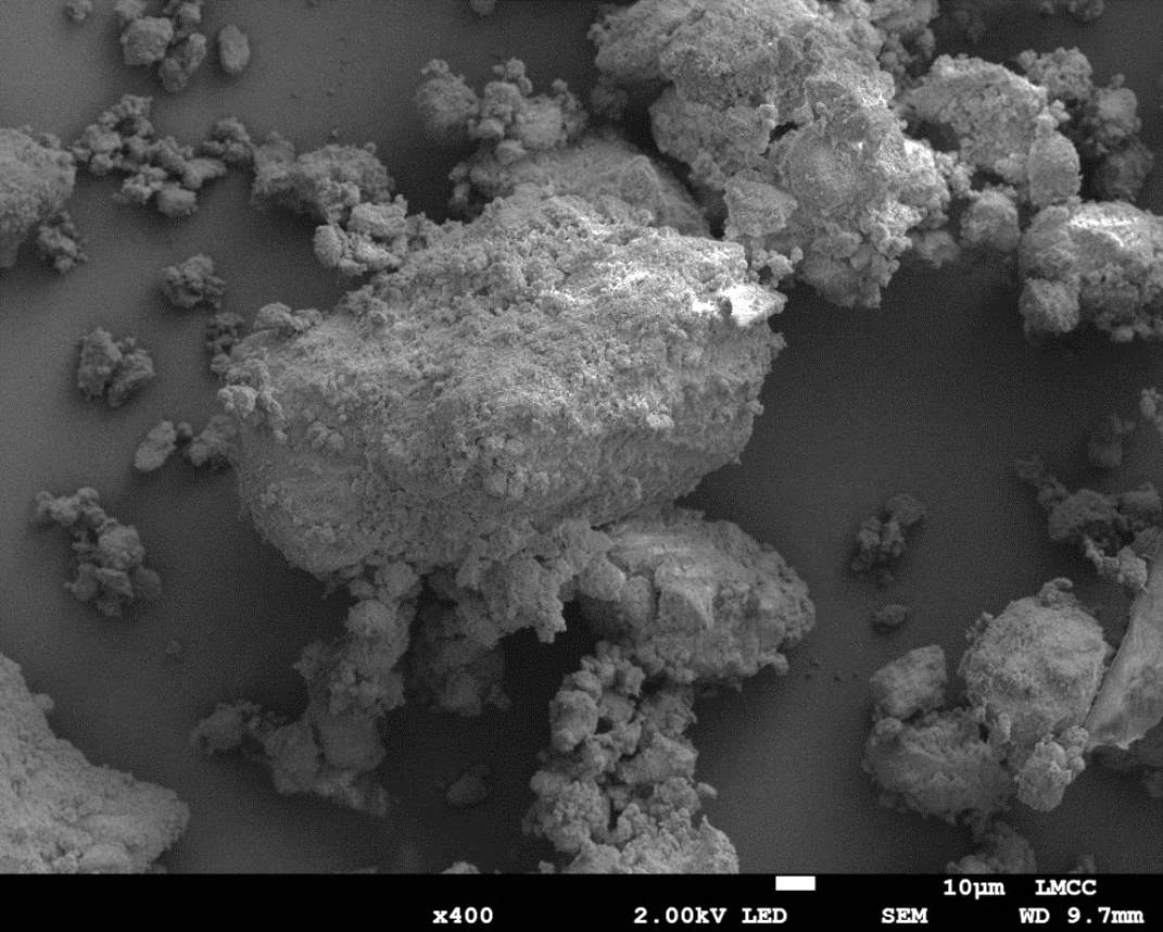
Figure 17: Sample 1 virgin Evonik ULTRASIL® VN3 GR SEM image x400 magnification
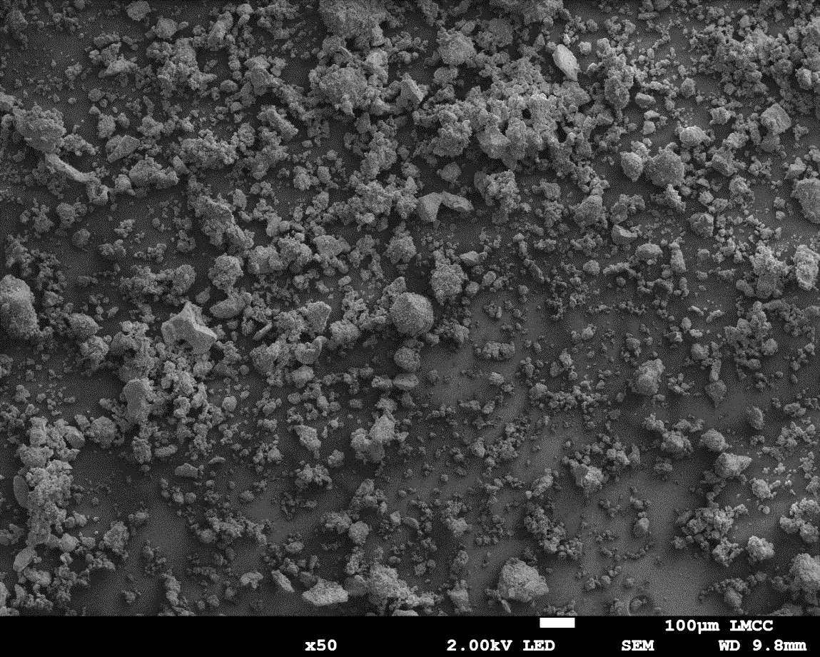
Figure 18: Sample 2 virgin Evonik ULTRASIL® 7000 GR SEM image x50 magnification
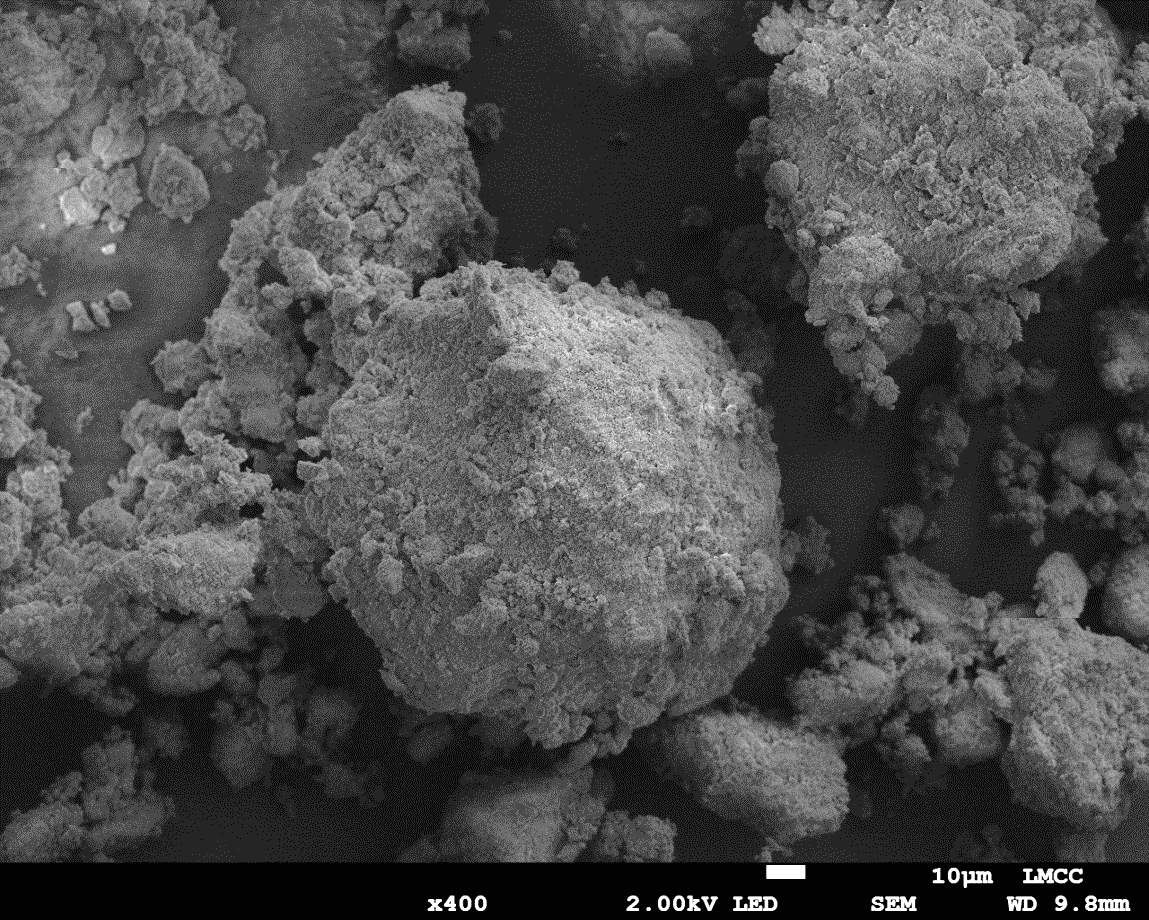
Figure 19: Sample 2 virgin Evonik ULTRASIL® 7000 GR SEM image x400 magnification
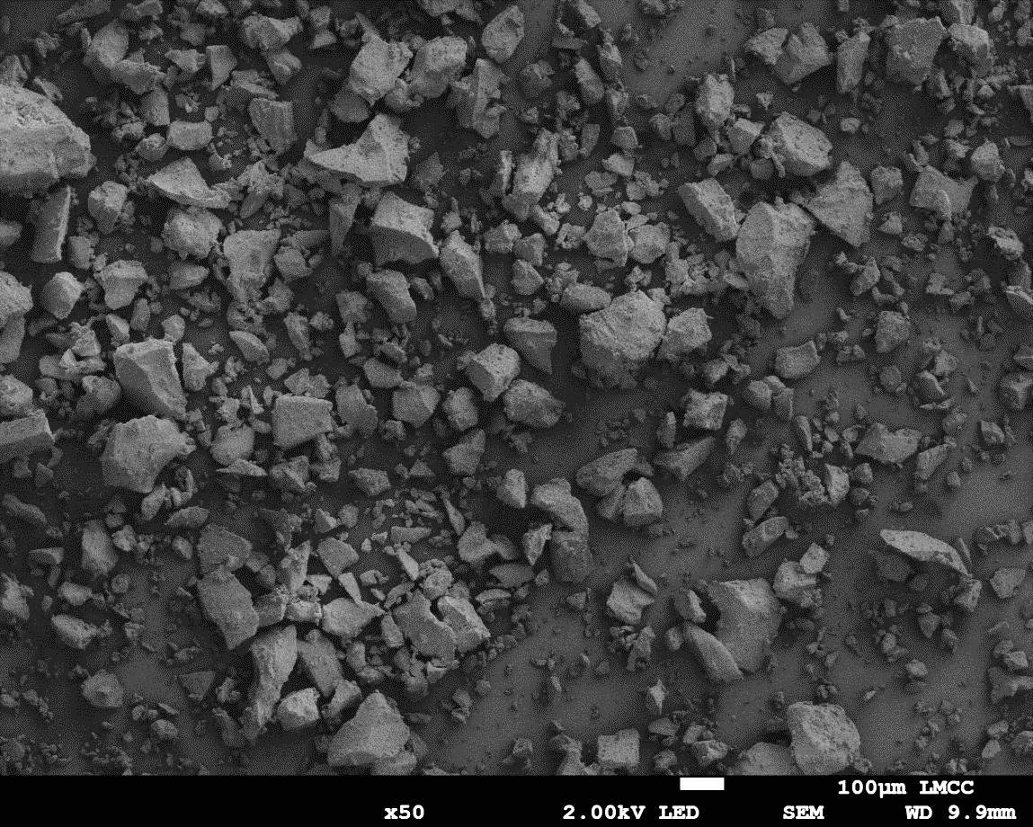
Figure 20: Sample 3 reclaimed Evonik ULTRASIL® 7000 GR at 500°C SEM image x50 magnification
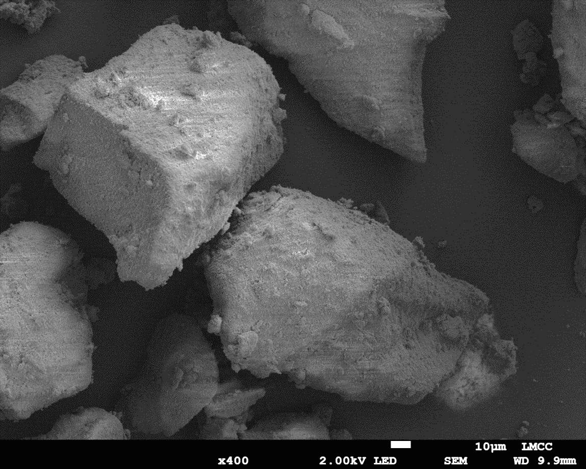
Figure 21: Sample 3 reclaimed Evonik ULTRASIL® 7000 GR at 500°C SEM image x400 magnification
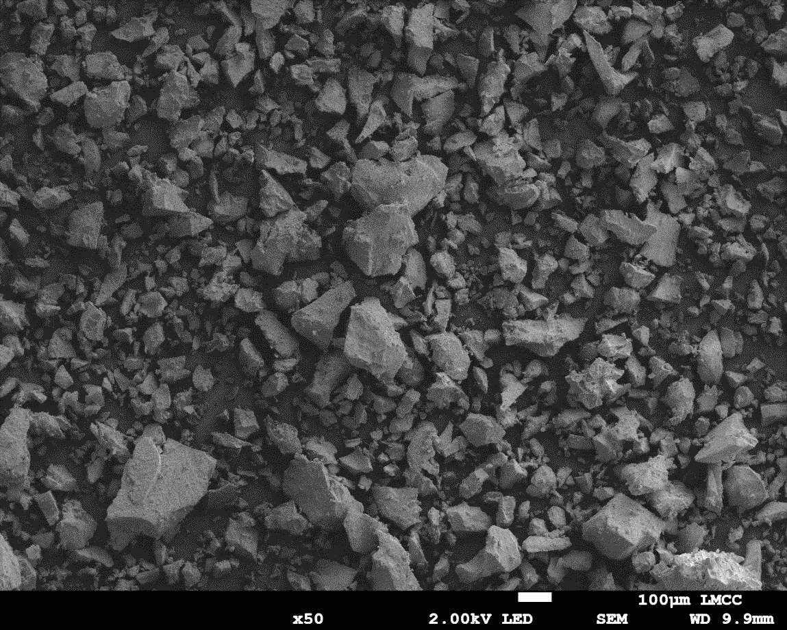
Figure 22: Sample 4 reclaimed Evonik ULTRASIL® 7000 GR at 650°C SEM image x50 magnification
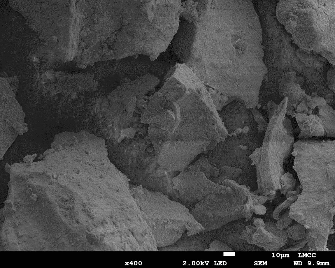
Figure 23: Sample 4 reclaimed Evonik ULTRASIL® 7000 GR at 650°C SEM image x400 magnification
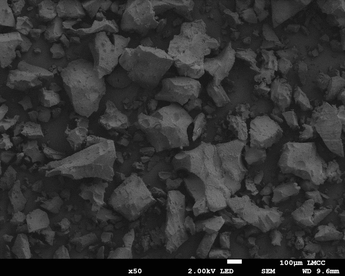
Figure 24: Sample 5 reclaimed Evonik ULTRASIL® 7000 GR at 800°C SEM image x50 magnification
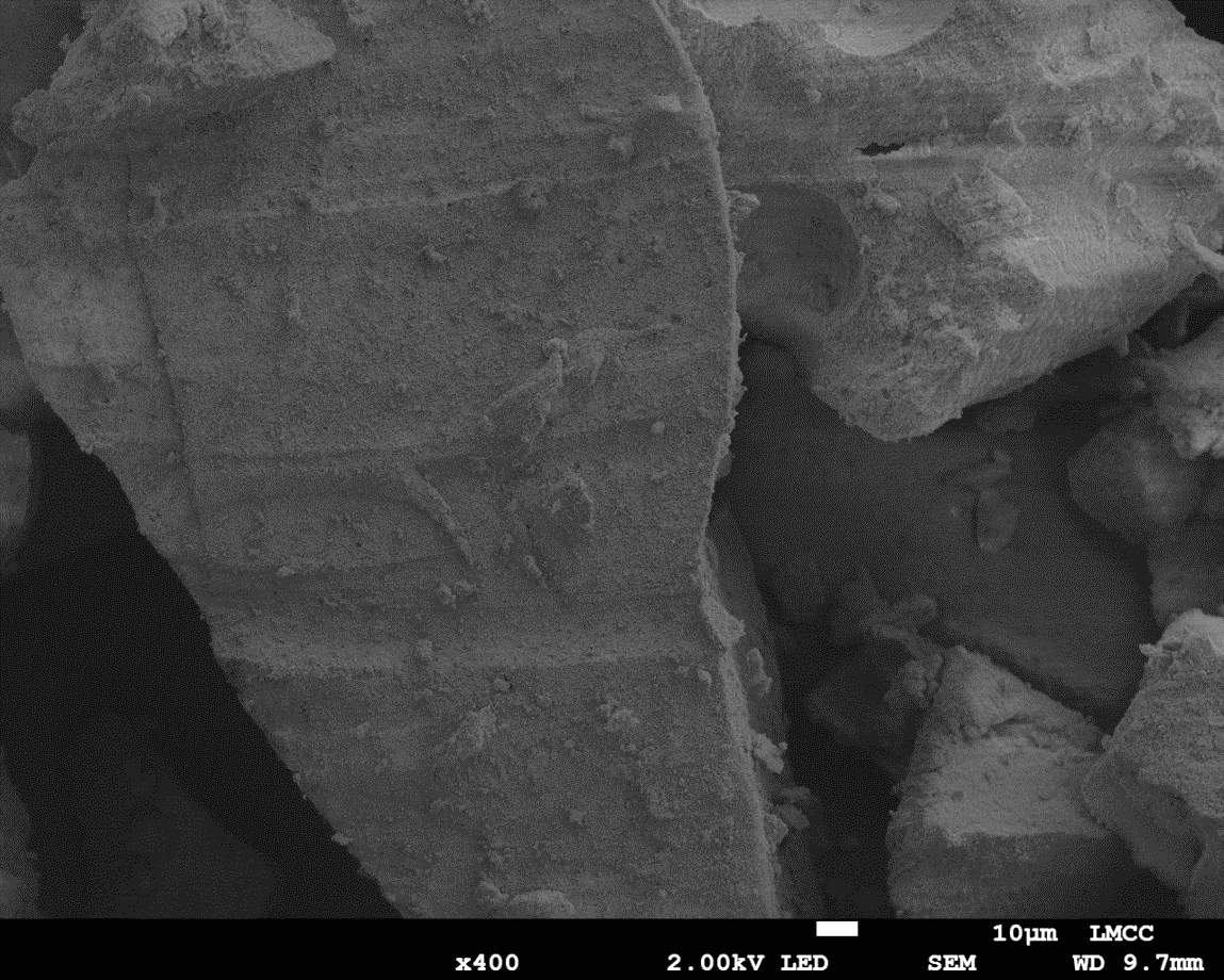
Figure 25: Sample 5 reclaimed Evonik ULTRASIL® 7000 GR at 800°C SEM image x400 magnification
5.1.2 Transmission electron microscopy
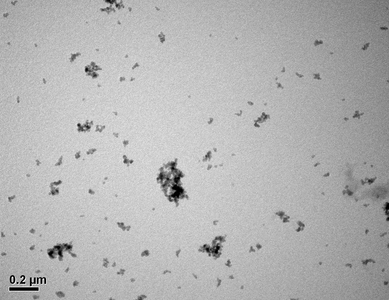
Figure 26: Sample 1 virgin Evonik ULTRASIL® VN3 GR TEM image x50k magnification
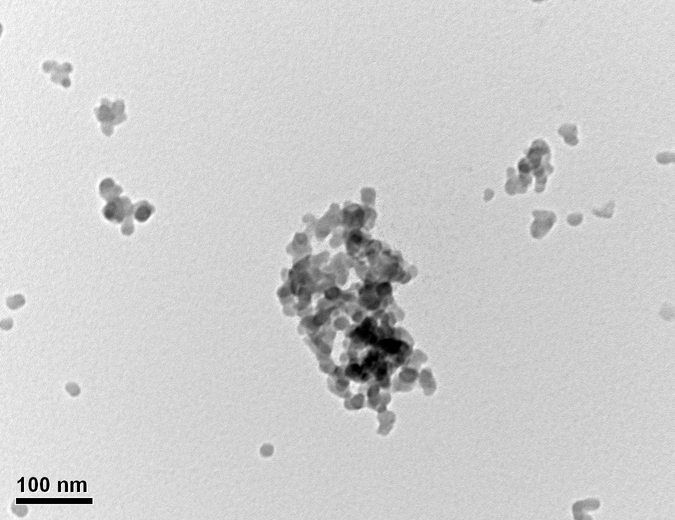
Figure 27: Sample 1 virgin Evonik ULTRASIL® VN3 GR TEM image x150k magnification
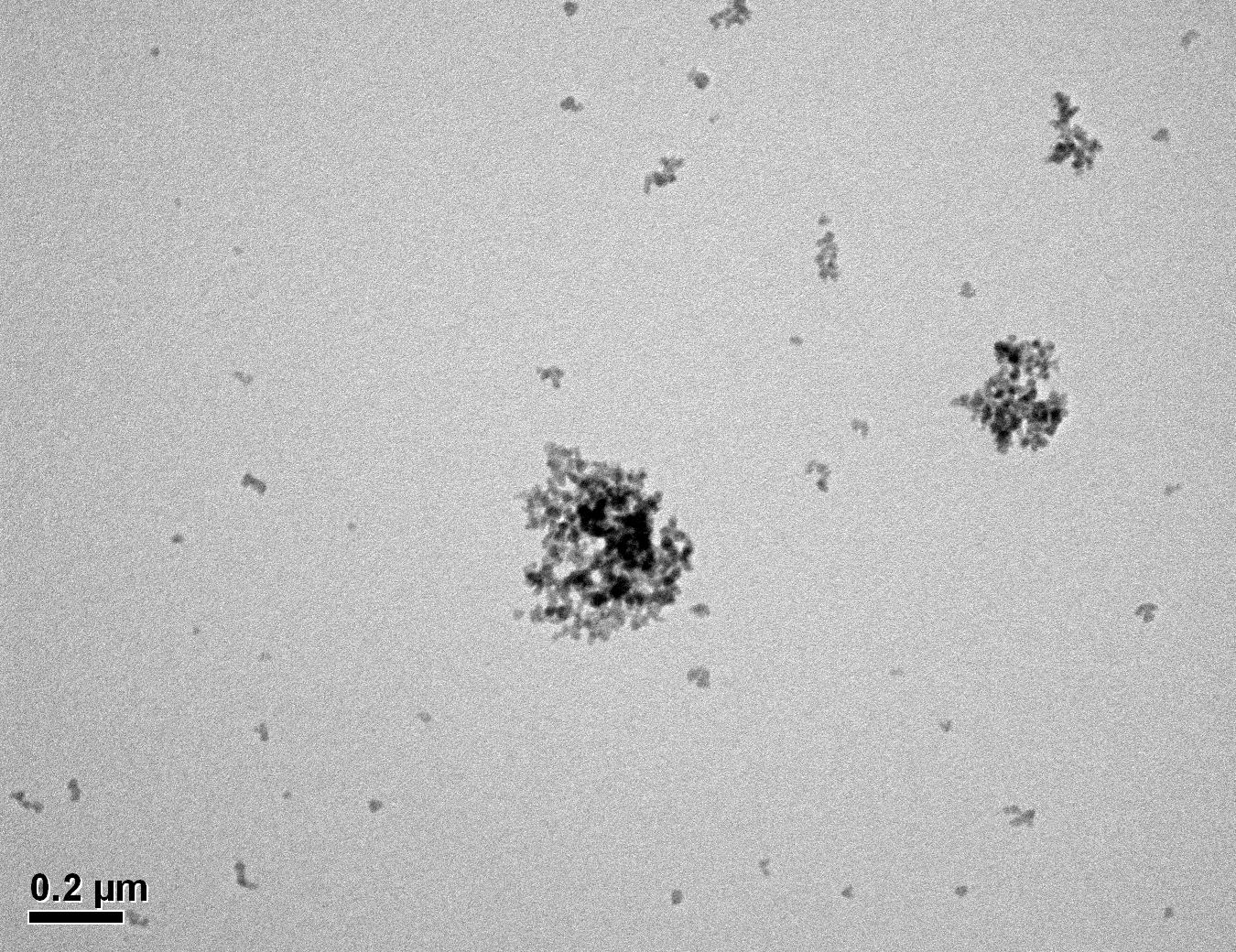
Figure 28: Sample 2 virgin Evonik ULTRASIL® 7000 GR TEM image x50k magnification
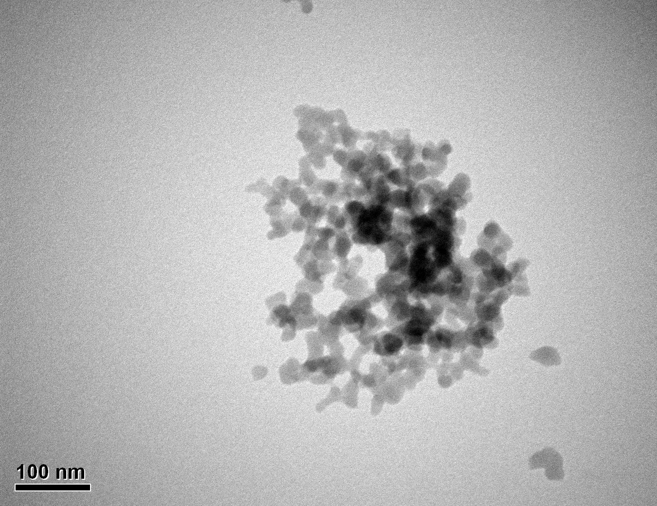
Figure 29: Sample 2 virgin Evonik ULTRASIL® 7000 GR TEM image x150k magnification
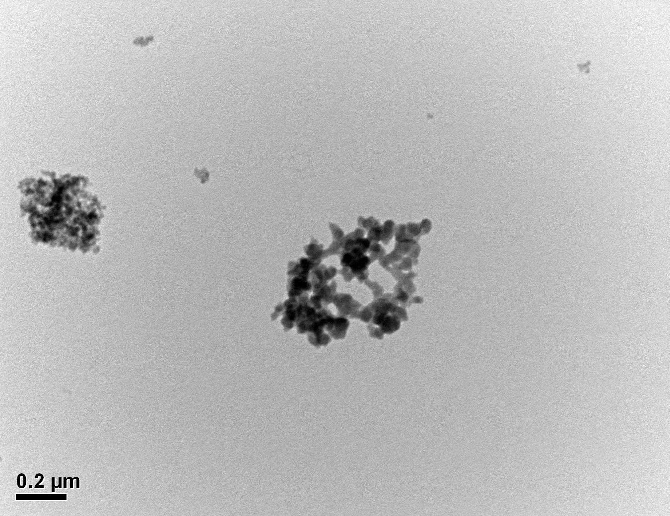
Figure 30: Sample 3 reclaimed Evonik ULTRASIL® 7000 GR at 500°C TEM image x50k magnification
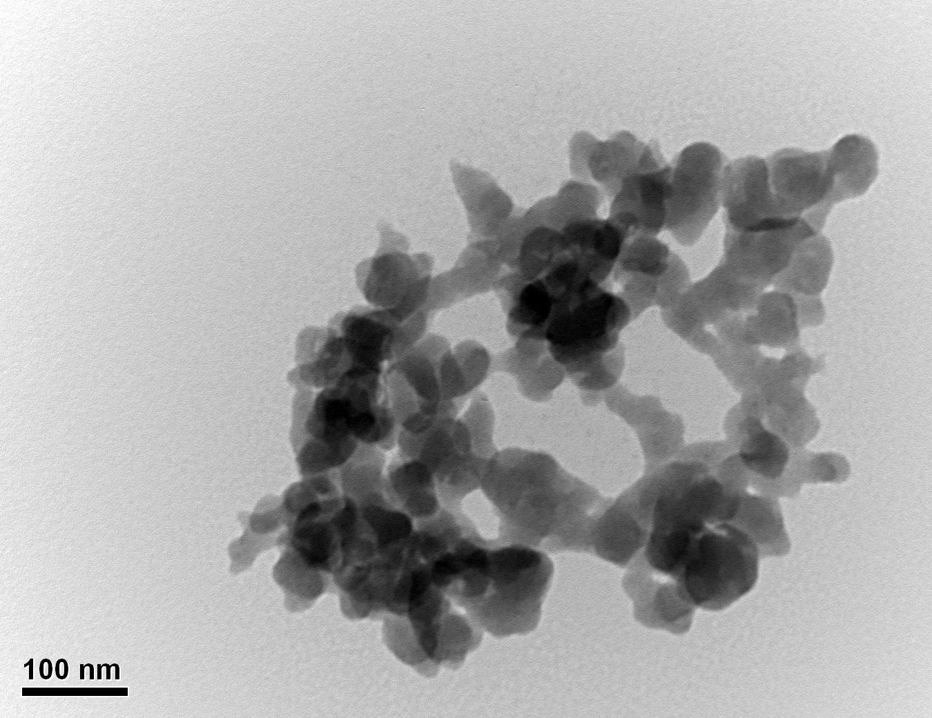
Figure 31: Sample 3 reclaimed Evonik ULTRASIL® 7000 GR at 500°C TEM image x150k magnification
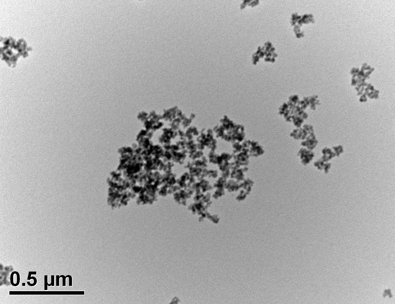
Figure 32: Sample 4 reclaimed Evonik ULTRASIL® 7000 GR at 650°C TEM image x50k magnification
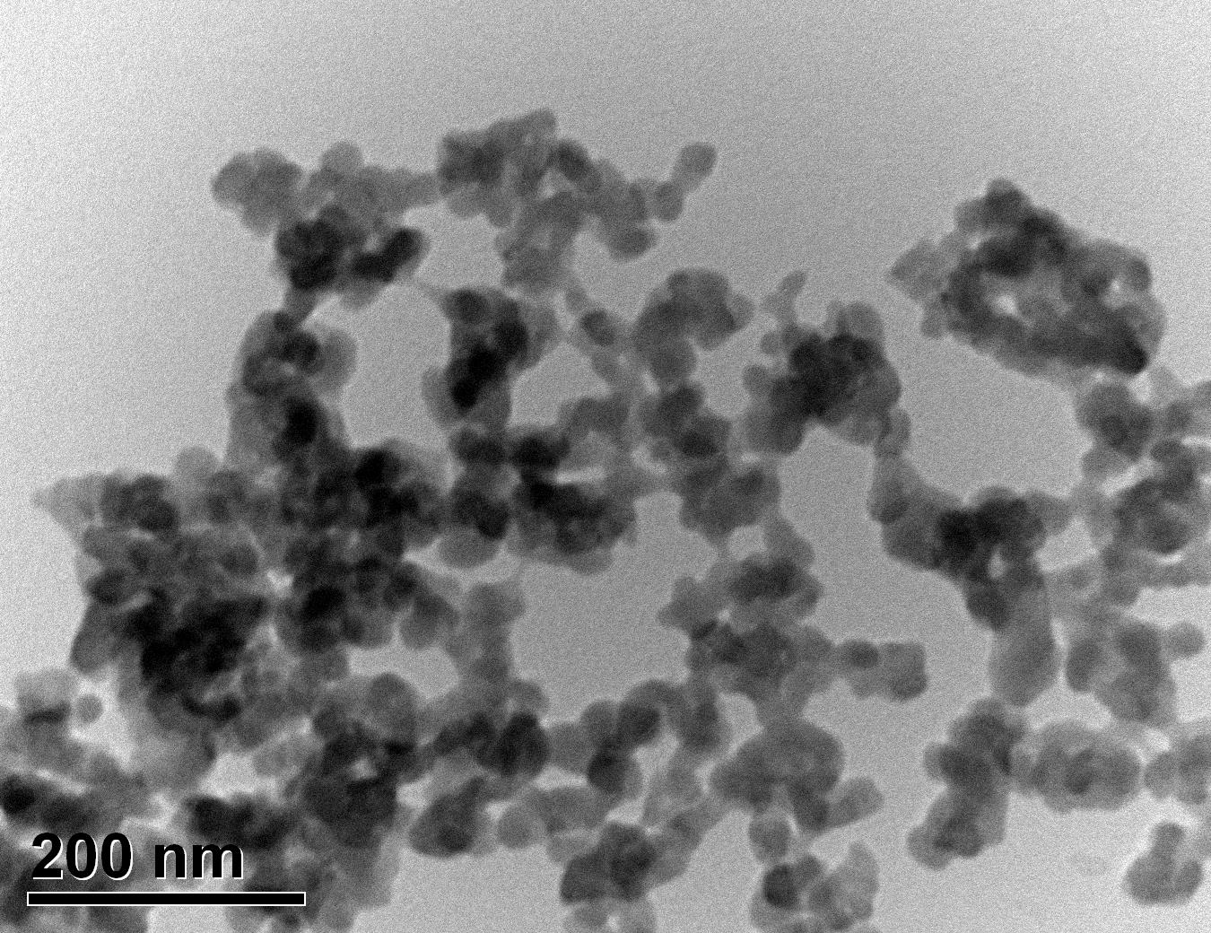
Figure 33: Sample 4 reclaimed Evonik ULTRASIL® 7000 GR at 650°C TEM image x150k magnification
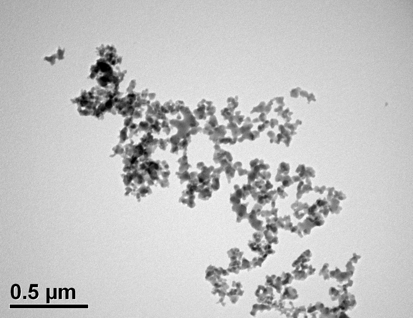
Figure 34: Sample 5 reclaimed Evonik ULTRASIL® 7000 GR at 800°C TEM image x50k magnification
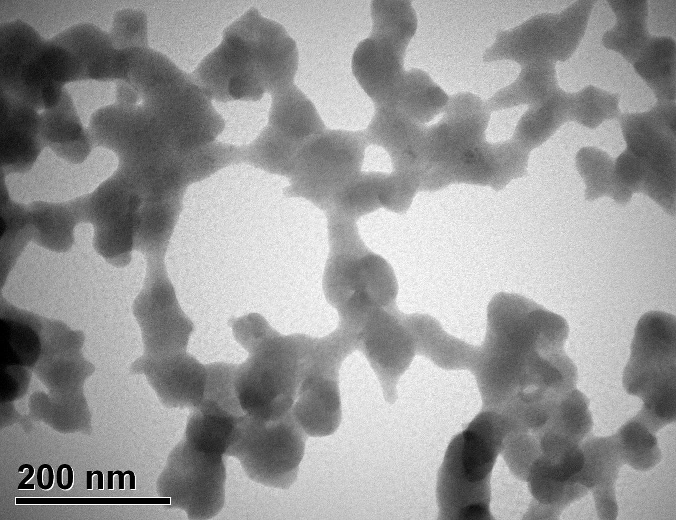
Figure 35: Sample 5 reclaimed Evonik ULTRASIL® 7000 GR at 800°C TEM image x150k magnification
6 Discussion: Part 1
During the scanning electron microscopy, images were taken of both the virgin and reclaimed silica’s nanoparticles at x50 and x400 magnification in order to compare any noticeable differences that may be exposed. The low magnifications of x50 are used to give indication of the largest cluster of particles and the high magnification images shows any other irregularities that may appear on the surface of the clusters along with examining small particles if present.
The two virgin silica’s examined in this project, Evonik ULTRASIL® VN3 GR and 7000 GR have very similar surface area values of 180 and 175 m2/g respectively and their SEM images are shown in Figures 16-17 and 18-19 respectively. From the images obtained, it is difficult to identify any differences between the two precipitated silica’s. The low magnification images of the virgin ULTRASIL® 7000 GR shows that particle clusters appear to be slightly larger than of the VN3 with a value of 180 and 200μm respectively. The high magnification images again show very little difference between the two with both cluster surfaces having equally course, rough appearance.
From Figures 18-19 and 20-2 of the benchmark material (Evonik ULTRASIL® 7000 GR) and the same material recovered at 500°C, it can be witnessed that there are noticeable differences in both the low and high magnification images whereas not much was examined when comparing the two virgin materials. The low magnification image of the reclaimed silica at 500°C shows more larger particles clusters in comparison to the virgin with the largest being approx. 230μm compared to 200μm from the virgin silica. The virgin 7000GR silica shows particle cluster appearing spherical with no noticeable sharp radial angles, however the same cannot be said regarding the reclaimed 7000GR at 500°C. The reclaimed 7000 GR particles show very sharp angles almost similar to what would be witnessed during a brittle fracture of a polymeric or metallic material. Given the high magnification images shown in Figure 19 and 21 it can be seen that the surface roughness of the particle clusters has reduced for the reclaimed silica in comparison to the virgin. While every characteristics differed when comparing the reclaimed silica at 500°C and virgin 7000GR, the smallest particle witnessed on the high magnification images was identical to the virgin with a value of approx. 4μm.
Low magnification images of the virgin 7000GR silica and reclaimed silica at 650°C in Figures 18 and 22 respectively, it can be said that the physical features of the reclaimed filler has altered similar to the reclaimed at 500°C silica; The reclaimed silica at 650°C exhibited similar characteristics of increased cluster sizes and sharp radial edges. From the higher marginations images of the reclaimed silica at 650°C shown in Figure 23, it can be seen that the radial angles are much sharper compared to the reclaimed 500°C silica (Figure 21). Given Figures 19 and 23, the high magnification images again show surface roughness of the clusters reduced in comparison to the virgin 7000GR but no noticeable difference between the reclaimed silica at 500°C and 650°C. Similar to other comparisons, the is very little change between the smallest particle cluster size with the reclaimed silica at 650°C exhibiting a value of 6μm compared to that of 4μm. However, the largest clusters continue to increase compared to the virgin material with a value of approx. 300μm for the reclaimed silica at 650°C.
The material that exhibited the largest particle cluster size by far was the reclaimed silica at 850°C with a value of approx. 450μm in compassion to its virgin material with a value of 200μm. The low margination image shown in Figure 24 showed the majority of the cluster being very large whereas the others reclaimed silica’s treated at 500°C and 650°C showed finer clusters. The high magnification SEM images of the reclaimed silica at 850°C shows that spherical clusters are replaced with sharp radial angles which have been witnessed in all reclaimed materials.
Transmission electron microscopy was conducted to show any indication of the state of aggregation after obtaining the reclaimed fillers from the rubber compound. Two images are included in this report per silica sample: a low magnification of 50k to show average agglomerate size and a high magnification on the largest agglomerate. From the TEM images shown in Figures 26-27 and 28-29 of the virgin Evonik ULTRASIL® VN3 and 7000 GR, it is shown that even the virgin material has some form of agglomeration associated with the silica particles. The virgin silica samples display agglomerations up to 400nm with some smaller agglomerates along with individual particles. Given the TEM images of the reclaimed silica’s shown in Figures 30-35, there is a clear indication that as the heat treatment process increases , the agglomeration sizes of the silica also increase. The reclaimed ULTRASIL® 7000GR at 500°C is the only reclaimed silica that shows individual silica particle along with large agglomerates of approx. 710nm which is more than double of what was witnessed in Figure 29 with its virgin material. The largest agglomeration of approx. 1750nm was observed in Figure 35 that shows the reclaimed silica at 850°C closely followed by the reclaimed silica at 650°C with approx. 1400nm.
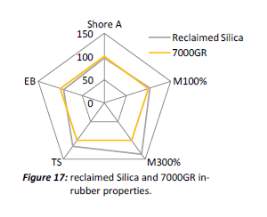
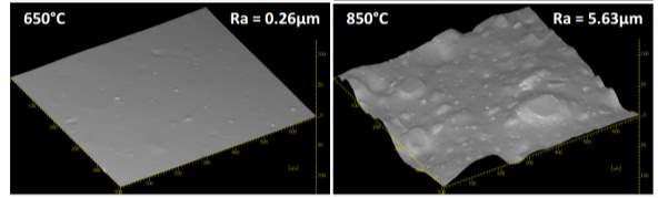
It is unclear why the explained characteristics above regarding the SEM and TEM images have occurred as the virgin silica’s are not salinised which could be playing a major factor, however, what is clear is the fact that dispersion of the reclaimed fillers is drastically reduced according to the roughness of rubber section shown below when the reclaimed materials are utilised as a reinforcing filler once again. dispersion is given by the Ra value and it can be seen that the reclaimed Evonik ULTRASIL® 7000GR at 650°C is similar to its virgin material regarding its ability to disperse with better micro-dispersion but poor macro-dispersion indicated by the impartially large bumps witnessed in figure 1. Unfortunately past experiments have not been conducted by ARTIS on the reclaimed silica at 500°C therefore only the virgin and other two reclaimed silica’s can be compared in this section. As expect from the TEM images of the reclaimed silica at 850°C, it has the least desirable dispersion of 5.63. Tensile tests performed on these compounds showed that the tensile strength of the recovered material at 650 °C actually showed an improvement is tensile strength of approx. 17% compared it virgin filler compound which could be due to the fact that zinc oxide is still present in the reclaimed silica possibly leading to increased crosslink density.
7 Results: Part 2
7.1 Chemical analysis
7.1.1 Fourier transform infrared spectrometer
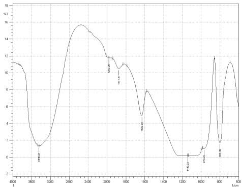
Figure 3: Sample 1 virgin Evonik Ultrasil VN3 GR at FT-IR spectrum.
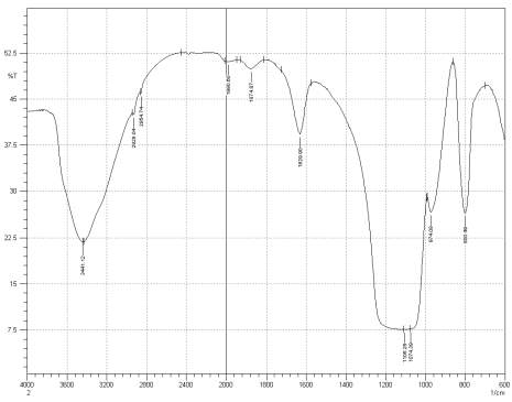
Figure 3: Sample 3 virgin Evonik Ultrasil 7000 GR FT-IR spectrum.
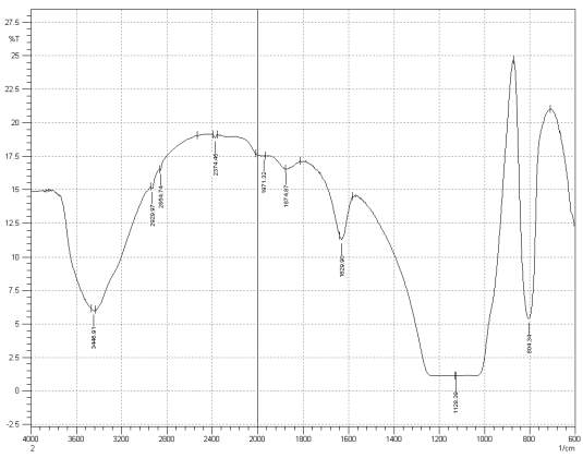
Figure 3: Sample 3 reclaimed Evonik Ultrasil 7000 GR at 500°C FT-IR spectrum.
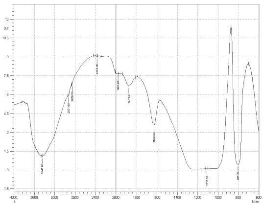
Figure 3: Sample 4 reclaimed Evonik Ultrasil 7000 GR at 650°C FT-IR spectrum.
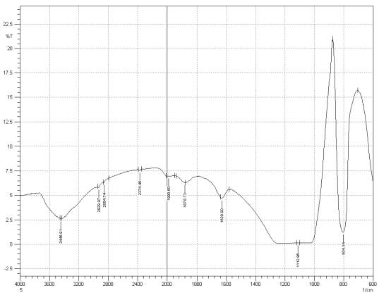
Figure 3: Sample 5 reclaimed Evonik Ultrasil 7000 GR at 800°C FT-IR spectrum.
7.1.2 EDS
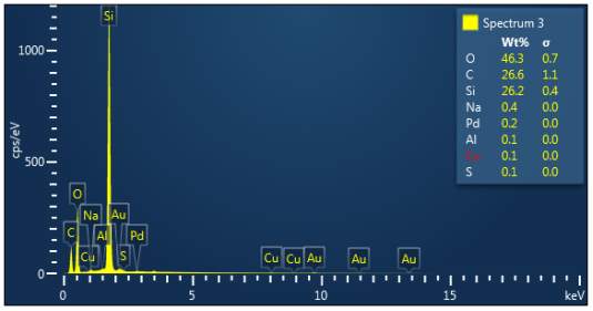
Figure 3: Sample 1 virgin Evonik Ultrasil VN3 GR EDX spectra.
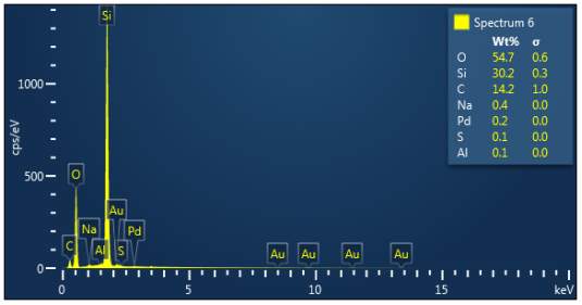
Figure 3: Sample 2 virgin Evonik Ultrasil 7000 GR EDX spectra.
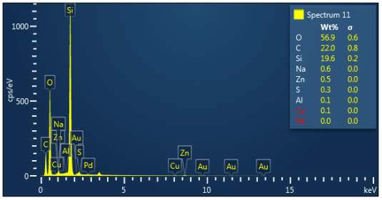
Figure 3: Sample 3 reclaimed Evonik Ultrasil 7000 GR at 500°C EDX spectra.
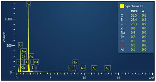
Figure 3: Sample 4 reclaimed Evonik Ultrasil 7000 GR at 650°C EDX spectra.
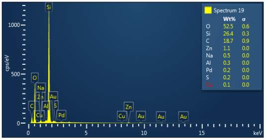
Figure 3: Sample 5 reclaimed Evonik Ultrasil 7000 GR at 800°C EDX spectra.
8 Discussion: Part 2
For Fourier transform infrared spectroscopy to be effective, the atom of the sample being tested most have some sort of chemical bond associated with it as the infra-red radiation causes vibration of these bonds with some being absorbed by the bonds while the rest is transmitted to the detector. The FT-IR spectrums is utilised in this case to identify any chemical changes that may have occurred during the reclamation process of the silica’s by comparing the peak value shown in Figure 1-3 across the x-axis representing wave length. All peak values have been listed in table 1 for comparison. Please note that peak at approximately 1300-1000cm-1 was not included in table 2 as the peak cannot be identified. The two virgin silica examined in the project, ULTRASIL® VN3 and 7000GR have very identical peaks with almost identical peak values but the noticeable difference between the two is the missing peaks of the VN3 silica at 2928.04 and 2854.74 cm-1. All reclaimed silica’s showed very similar peak values to its virgin ULTRASIL® 7000GR with the exception of the peak at 970.08 cm-1 that is non-existent in the reclaimed fillers indicating some chemical change has occurred during the reclamation process.
| Sample1 | 3446.91 | – | – | 2375.62 | 1980.96 | 1874.87 | 1629.90 | 970.23 | 800.49 |
| Sample2 | 3441.12 | 2928.04 | 2854.74 | 2375.60 | 1990.60 | 1874.87 | 1629.90 | 974.08 | 800.49 |
| Sample3 | 3448.91 | 2929.97 | 2854.74 | 2374.45 | 1971.32 | 1874.87 | 1629.90 | – | 804.34 |
| Sample4 | 3446.91 | 2931.90 | 2860.53 | 2374.45 | 1980.96 | 1874.87 | 1629.90 | – | 806.27 |
| Sample5 | 3446.91 | 2929.97 | 2854.74 | 2374.45 | 1990.60 | 1878.79 | 1629.90 | – | 804.34 |
The X-ray analysis of the scanning electron microscopy was used to determine elemental composition of the silica to identify if any composition change has occurred during the reclamation process. Each peak shown in the spectra’s (Figures 1- 2) corresponds to a specific element and the more of that specific element present, the larger the peak hence why silicon is one of the highest throughout the spectra’s. The tables on the side of each spectra shows the weight percentage of a detected element; please note that any elements highlighted in red have either been detected incorrectly or very small amount have been detected but from examining the results they are likely to be incorrect. The two virgin silica: ULTRASIL® VN3 and 7000 GR show identical compositions with copper incorrectly identified for the virgin VN3 shown in figure 1. Palladium has been highlight in red for the reclaimed sample at 500°C (figiure1) but this is again incorrect as the both virgin and reclaimed materials also detect this element. The only difference between the reclaimed 7000GR silica’s and it virgin material is the addition of zinc oxide that was used as an activator during mixing. This additional zinc oxide may impose additional benefit in comparison to its virgin material as discussed in previous section.
9 Conclusion and recommendations
From the work conducted in this project it can be concluded that:
- Silica is used in rubber formulation, especially in tyres to reduced rolling resistance that in turn reduced fuel consumption and greenhouses gasses admitted.
- Physical characteristics and chemical composition of reclaimed silica changed in comparison to its virgin material regardless of temperatures used to reclaim the material from rubber
- Virgin silica cluster surface appear to have a rough appearance in comparison to the reclaimed fillers that get smother as heat treatment temperature to reclaim silica increases
- The largest silica cluster size increases drastically with increasing temperatures to reclaim silica with the lowest being the VN3 with a value of approx. 180 closely followed by the virgin 7000GR: 200. The large cluster was measured to be 1450 for the reclaimed 7000GR silica at 850.
- While the smallest cluster size was very difficult to locate given the magnifications, there was no signifant difference between samples
- The virgin silica clusters are very spherically in their appearance but as the treatment temperature of the reclaim process increases, the spherical like clusters transfers to sharp radial angles similar to a brittle fracture.
- No significant difference bentween the two virgin materials: ultrasil VN3 and 7000 GR in respect to their physical features.
- Tem imaging results showed that the state of aggrogoation of the silica particles increases in respect to higher temperatures utilised in reclaiming silica from tyre tread formulation.
- The large agglomerates witnessed in the 7000GR silica reclaimed at 850 showed the worse dispersion when mixed back into a rubber compound once more as a reinforcing filler.
- Fourier transform infrared spectrometer showed no difference between the virgin 7000Gr and reclaimed fillers regardless of temperatures utilised to reclaim silica with the exception of a missing peak of 970.08 for all reclaimed silica’s
- The FTI-IR spectrums for the two virgin silica showed identical peaks 2928.04 and 2854.74 missing from the VN3 silica
- The X-ray analysis showed compisional change had occurred to the reclaimed silica with the addition of zinc oxide that was original used as an activator. This addition may of incease the cross density in comrison to it vigin material as in-rubber properties showed at 17% increase in tensile strength of the reclaimed silcai at 650.
Further work to be conducted in order for a better understanding of why reclaimed silica properties change includes:
- Analyse virgin silica samples that have also been silianised to get better understanding of the difference and eliminate coupling agent from the cause
- In-rubber properties and dispersion of the reclaimed silica at 500 to find the optium silica reclaiming temperature as dispersion of the reclaimed silica at 650 was more the acceptable and gave high tensile strength than the virgin silica.
- the milling of reclaimed silica to examine if in-rubber properties and dispersion improves as this has been proven to be effective with reclaimed carbon black
- reclaim the ultrasil VN3 from a rubber compound to anylsye whether similar charcaterris are showed to that of witness with the 7000gr silica. Reclaimed VN3 is likely to be idendical as it showed very little differences with the 7000 gr silca
10 References
[1] Silica Reinforced Tyre Rubbers. 2002.
Cite This Work
To export a reference to this article please select a referencing stye below:
Related Services
View all


Related Content
All TagsContent relating to: "Sciences"
Sciences covers multiple areas of science, including Biology, Chemistry, Physics, and many other disciplines.
Related Articles

DMCA / Removal Request
If you are the original writer of this dissertation and no longer wish to have your work published on the UKDiss.com website then please: