Computer Simulator for Shooting Practice
Info: 11873 words (47 pages) Dissertation
Published: 11th Dec 2019
Tagged: TechnologyLaw Enforcement
ABSTRACT
Simulation is the process of creating a virtual world which enables people to encounter the reality. A simulator is a computer program or a dedicated device that models some aspects of a real life situation and can be manipulated to observe that outcomes of different assumptions or actions without exposing to any danger. It helps trainees in defence to target the enemy through the process of image detection. A gun is aimed at the target with the help of infrared radiations which are detected by IR detector. An infrared detector is a transducer of radiant energy that converts radiant energy in the infrared into a measurable form. An infrared detector is a detector which reacts to infrared radiation. The accuracy of the trainee is determined by the distance between the target point and the aimed point. The performance of the trainee is visualised by instruction station. The application aims at multiple trainees targeting one screen at the same time. Using the concept of image processing the trainee is identified. There are three main components: input/output, visual station, instruction station. Instruction is a place where simulation is monitored. Visual station is a place where 3D visualization, animations are examined. Input/ Output is where actual process of simulation is performed. The simulator uses modified in-service weapons for recoil effect. It can be configured with a number of Small Arms, including 9mm Pistols, Revolvers, INSAS 5.56 mm range of weapons, 303 Rifles, AK-47s, 7.62mm SLR ,Carbines and Light Machine Guns. It can also be configured with shoulder-fired Rocket Launchers of all makes. It allows the user to fire from any position i.e. lying, kneeling or standing down.
CHAPTER 1
INTRODUCTION
The Simulators for homeland Security is a multipurpose simulator that helps training in all aspects of firing from basic to advanced firing skills that are required during conflict situation. Simulation is creating virtual world for soldiers who are yet to begin training and helping them to use the guns in the war effectively. 3D image generation provision is there in simulators to re-create real time environment onto the projection screen along with synchronous sound effects. The operation of a real-world process over time Simulation is constraint of. The model that is to be developed indicates the system itself for real world system, whereas the simulation indicates the operation of the system over time. Computer simulation is creating an real world system with actual working of the system and the tests are conducted on the model. Simulation can be used to show the eventual creating a virtual world else creating he exact real world for the trainees and courses of action.
Simulation: In real-world process or system it acts parody over time. The main logic of simulation is to create model that contains the characteristics same as that of the real environment. A normal model represents the system but simulation actually helps us to real environment at any time. This project mainly deals with training. Simulation can be used to portray various kinds real actions virtually which resembles to be real. Children always enacts different role plays, simulator is as similar to that role plays. Children perceive the globe around them by simulating most of their interactions with people, animals and objects. As adults, we tend to lose a number of this childlike behaviour however recapture it afterward through framework. In order to actually know reality we need to build various dynamic objects through simulators. Computer simulation is the electronic equivalent of this kind of role taking part in and it serves to drive artificial environments and virtual worlds.
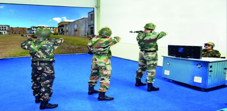
Figure 1.1.1 homeland simulation
Simulation is very important in the following basis, when the interacting components or variables is very complex to model, if there are nonlinear relationships between variables, if it contains random variables, the model output will be same like as in a 3D computer animation it shows visually. The most important thing is the simulation replicates the one in the real environment..
Simulation acts as a very important role because it allows to experiment each and every thing rather than on real system. Therefore it reduces time and also decreases fear of losing the real system. That is, it allows you to ask “What if?” questions about a system without having to experiment on the actual system itself. It should be used when we actually cannot examine in the real system. The consequences are delayed in time a dispersed in space or it is simply impractical or prohibitively expensive to test the alternatives directly.
A computer simulation allows us to create a real and hypothetical system where we can illustrate and examine different system. By dynamic variables inside the simulation, predictions are created concerning the behaviour of the system. It’s a study during which the behaviour of the system is examined nearly. A decent example to truly apprehend the instance of model is traffic simulation.
A number of simulated events can be created by software programs which are the most common forms of computer simulation technology. To test a range of products different pieces of software’s have been designed to help people simulate various simulations. For example, many realistic series of events can be recreated by software programs to test how well a building might hold up to high winds and earthquakes. There are many other programs that have been developed as computer simulation technology which include industrial products prior to construction and software used to test designs for cars and other commercial. Despite learning in a real world environment there are some physical simulators that allow someone to train through a virtual reality or simulated scenario. Flight simulators, for example, often use hardware that emulates the controls of a cockpit and internal displays, to allow pilots to learn different flight procedures in a safe setting.
Flight and racing simulators, for example, typically contain programs that produce a virtual environment on a chain of monitors, which changes based on the simulation controller. A virtual reality landscape is allowed to be seen by the users that are programmed to be responsive based on input through simulation hardware. Emulators are some type of technologies that are referred by some types of computer simulation technology. These computer code programs enable somebody to emulate a unique hardware or computer code setup, while not having to use the particular hardware. For example, emulators can be used by software developers to test different hardware configurations for a new program, instead of building numerous physical environments for testing. Older pieces of technology can be recreated by some emulators, such as video game hardware, to allow people to play an older game on newer devices.
The simulation is used in military, defence for training of soldiers. This sometimes happens once it’s prohibitively costly or just too dangerous to permit trainees to use .It allows the trainees to learn in a safe environment rather than in dangerous surroundings. Most probably there is convenience in allowing mistakes throughout coaching for a safety-critical system.
Training simulations generally are available in of those following classes, live simulation may be a simulation wherever players can play with actual systems or in a very real atmosphere, virtual simulation permits player to feel or enclosed in a very real atmosphere. In standardized tests, live simulations square measure generally known as accurate, manufacturing samples of doubtless performance, as critical low-fidelity, pencil-and-paper simulations manufacturing solely signs of doable performance.
1.1 SCOPE AND PURPOSE OF THE SYSTEM
This application helps multiple trainees to target at a given point at the same time and their points are noted in scoreboard which helps the trainee’s performances. A gun is aimed at the target with the help of infrared radiations which are detected by IR detector. The accuracy of the trainee is determined by the distance between the target point and the aimed point. The performance of the trainee is visualised by instruction station. The application aims at multiple trainees targeting one screen at the same time.
They can handle a variety of weapons such as:-
- 9mm Pistols
- Revolvers
- Light Machine Guns
- Rocket Launchers
- 303 Rifles
- INSAS 5.56mm
- AK-47
The performance of the trainees in Real time is tracked by the guided missile simulator which is enabled by the instructor. The training scenarios can be configured in accordance with the skill levels of trainees. There are many applications, simulators are majorly used in Driving, Minning, Defence and homeland security.
Virtual driving is experienced with the help of simulators.When a driver before actual driving in a vehicle a virtual world model is developed where the driver experiences real world entities and a projection screen with a synchronous sound effects which helps the driver to drive carefully before actually entering into real world.For an instance when a pilot experiences virtual system as during the war fare that pilot have to understand the rules and the virtual driving helps in moving the actual plane more safely.
For homeland security when trainees before giving an actual gun there training has to be done in a virtual system in which they can understand the actual working go guns and which helps in targeting the target. With the help of the simulators the trainees are given different types of guns to help them to see how it actually works and the projection screen helps them to fire the target. This improves the performance of the trainees.
1.2 EXISTING SYSTEM
Virtual simulators are referred to as indoor simulators. These simulators are modelled on the lines of the initial military instrumentation that they need been designed to impart coaching and designed to make varied computer-generated virtual three-D environments, below that military personnel are often trained. Live simulators are referred to as out of doors simulators, as they’re used for live combat coaching. These simulators are original military instrumentation fitted with laser-emitting devices and sensors to measure the performance of a beginner. Constructive simulators are referred to as processed war diversion simulators. This sort of simulators train military personnel with the assistance of computers that use logical and mathematical modelling to represent the dynamics of combat coaching.
The land-based coaching and simulation market includes simulators for military land instrumentality and systems. This phase encompasses simulators for little arms, grenades, larger weapons like anti-tank missiles, tanks, armoured vehicles, and different land systems. The Indian Army, paramilitary forces, and central and state polices forces square measure the most finish users during this market phase.
The performance of the trainee is identified by the accuracy of his performance by calculating the distance between the target point and the aimed point. When multiple trainees are targeting at one point, with the help of timestamp the target point is differentiated. When multiple trainees are targeting at one point, as all guns have similar laser points hence with the help of timestamps it takes some time to detect from which gun the target is fired.
1.3 PROPOSED SYSTEM
Multiple trainees target points are differentiated through symbols without any deceleration. Four trainees can be trained simultaneously which can be even upgradable to even 8. This system helps in identifying from which gun the target point is fired and the optimization of time is possible through this system. It also makes analysing very easy. Guns laser points are made in different symbols and given it to the player. It is played in a virtual environment.
CHAPTER 2
FEASIBILITY STUDY
Feasibility is an evaluation of the proposal is to determine the difficulty in carry out a task. Generally feasibleness precedes technical development and project implementation in different words, a feasibleness study could be a evaluations or analysis of the potential impact of the projected project. During this section and business proposal the feasibleness of the project is analysed is place forth with a general arrange for the project and a few estimation in prices. Three key concerns concerned within the feasibleness analysis ar economic feasibleness, technical feasibleness, and social feasibleness.
2.1 ECONOMICAL FEASIBILITY
This study is meted out to envision the economic impact that the system can wear the organization.In our project, there’s no want for purchase of any commercially accessible package or tailored product as a result of we have a tendency to solely use technologies that area unit liberated to use, and that we have created everything ourselves. The effectiveness of a new system is a frequently used method for evaluating Economic analysis is the most frequently. Generally it is known as cost or benefit analysis, the procedure is set to provide the benefits and savings that are related to a candidate system and contrasts with costs. It benefits outweigh costs, the action is proceeded an entrepreneur must weigh approximately between cost and benefits.
Cost-based study: Cost and benefit factors is very important to identify, which can be classified as follows: 1. Development costs; and 2. Operating costs. Benefits should be derived out of the system and cost should be examined within the system.
Time-based study: This is an analysis of the time required to achieve a return on investments. The future value also acts as a factor in the project.
2.2 TECHNICAL FEASIBILITY
Study is carried out to check the technical feasibility, that is, the technical requirements of the system. Any system developed should not have a high demand on the accessible technical resources. If placed on consumer this will result in higher demands. The developed system should have a modest requirement; as solely negligible or null changes ar needed for implementing this method.
2.3 SOCIAL FEASIBILITY
The level of acceptance of the system by the user checking is the main aspect of the study. This includes the method of coaching the user to use the system with efficiency. The user should accepts it as necessity instead of feeling it as vulnerable by the system. The extent of acceptance by the users only depends on the strategies that square measure used to teach the user concerning the system and to create him acquainted with it. In order to make a constructive criticism his/her confidence must be build, which is welcomed, as he/she is the final user of the system.
Our project is by far, better than what we currently have available. There is no need for user training as everything is self – explanatory and extremely easy to use while being user friendly and with a minimalistic approach.
CHAPTER 3
SYSTEM ANALYSIS
This System Analysis is closely related to requirements analysis. It is also “an explicit formal inquiry carried out to help someone identify a better course of action and make a better decision than he/she might otherwise have made. To analyse things this step involves breaking down the system in several items, analyse project goals, definite necessities will be outlined by breaking down what has to be created and making an attempt to have interaction users.
Performance is measured in terms of the output provided by the application. Requirement specification plays an important part in the analysis of a system. Because they are the people who finally use the system It rests largely with the users of the existing system to give the requirement specifications. This is because the requirements have to be known during the initial stages so that the system can be designed according to those requirements. Once it has been designed it is very difficult to change the system and on the other hand designing a system, which there is no use of the requirements to user . The specification for the requirements of any system can be broadly said as given below:
- The new system should be able to interface with the existing system
- The new system should be precise
- The proposed system is much more fast then the existing system.
- The new system should be good than the existing system.
Requirements may be specified in a variety of ways. However, there are some guidelines worth following:
- All the representation format and content should be related to the problem.
- All the information included within the specification should be iterated.
- Diagrams and alternative notational forms ought to be restricted in range and consistent in use.
- Representations should be revisable.
At the pinnacle of the analysis task the software requirements specification is produced. The function and performance allocated to the software as a part of system engineering are refined by establishing a complete information description, a detailed functional and behavioural description, and detection of performance requirements and design limitations, proper validation criteria and other data relevant to requirements.
3.1 FUNCTIONAL REQUIREMENTS
Functional requirements were obtained from a variety of sources including typical scenarios, Army Training and assessment Programs situational training exercise and battle drills. These requirements defined the processes and representations that must satisfy to achieve its intended training goals. Functional requirements included the categories were those consisting to terrain, movement, detection/identification, engagement, and indirect fire. As the functional requirements were being prepared information was obtained on the hardware, software, and peripherals that would be required to support the functional requirements.
3.2 NON-FUNCTIONAL REQUIREMENTS
The simulation display keeps up with actual time the number of drivable lanes shall be updated in real time when a lane is closed or opened. The update time shall be done according to simulation time. The time of day shall be displayed to the user. Static Population distributions shall be provided. When player is pointing, the system should show the results on screen.
3.3 HARDWARE REQUIREMENTS
- Processor – Intel P-IV based system
- RAM – 256MB
- Hard Disk – 4GB to 30GB
- Projector
- Guns
- IR detector
3.3 SOFTWARE REQUIREMENTS
- Operating system-Windows 8.1
- Technology-C#
- Platform-Visual Studio
CHAPTER 4
SYSTEM DESIGN
4.1 SYSTEM ARCHITECTURE
The input design is an association between the user and the information system. It comprises the developing specification and procedures for data preparation and those steps are necessary to put transaction data in to a usable form for processing can be achieved by observe the computer to read data from a printed document or written it can occur by having people keying the data immediately into the system. The design of input focuses on controlling the amount of input required, controlling the errors, avoiding delay, avoiding extra steps and keeping the process simple. The input is delineate in such a way so that it produce security and ease of use with preserving the seclusion. Input Design considered the following things:
- What data should be given as input?
- How the data should be arranged or coded?
- The dialog to guide the operating personnel in providing input.
- Methods for preparing input validations and steps to follow when error occur.
Input Design is the process of transfigures a user-oriented illustration of the input into a computer-based system. This delineate is powerful to circumvent errors in the data input process and show the error-free bearing to the management for getting correct information from the computerized system. It is by attaining user-friendly screens for the data entry to hold huge amount of data. The goal of designing input is to make data entry easier and to be free from errors. The data entry screen is delineated in such a way that all the data manipulations can be performed. It also provides record viewing facilities. When the data is entered, it will check for its validity. Data can be inserted or altered with the help of screens. Appropriate messages are provided as when needed so that the user will not be in maize of instant. A quality output is one, which meets the requirements of the end user and presents the information clearly. . Thus, the objective of input design is to create an input layout that is easy to follow.
The requirements which meets the end user and presents the information clearly gives a quality output. In any system results of processing are communicated to the users and to other system through outputs. The information is displaced for immediate need and also the hard copy output is to be determined in an output desgin. It is the most important and direct source information to the user. Well organized and intellilectual output design improves the system’s relationship to help the decision-making of the user.
Each output element is designed so that people will find the system can use easily and effectively if the designing computer output should proceed in an organized, well thought out manner; the right output must be developed . When analysis design computer output, they should identify the specific output that is needed to meet the requirements.
- Select methods for presenting information.
- Create document, report, or other formats that contain information produced by the system.
The output form of an information system should accomplish one or more of the following objectives.
- Convey information about past activities, current status or projections of the system.
4.2 MODULES
It consists of three modules:-
- VISUAL STATION
- INSTRUCTION STATION
- INPUT/OUTPUT STATION
VISUAL STATION-Visual station acts as a GUI to the application. It actually acts as the interaction between the human and the computer. For example at a store counter, office front desk, or building reception area, setting up a PC solely for surveillance purposes would be overkill or impossible due to limited space or budget. In such scenarios, Visual Station is the perfect alternative. Just plug in an Ethernet cable, connect to an LCD-monitor or TV, log in to Synology Surveillance Station and you’ve set up a monitoring station for yourself.
We turn it into a landscape that can be explored with your eyes by visualizing information, a sort of information map. And when you’re lost in information, an information map is kind of useful. Well put. In fact, the “map” that visualization provides is downright essential when dealing with massive amounts of data that would otherwise be very difficult to process and extract actionable insight from.
Visualization stimulates fast understanding across teams, making sense of data with great volume, velocity and variety. It brings data to life and puts it in story form, how people want to consume it; hitting a different part of the brain that encourages retention. In the age of big data, visualization provides the missing link utility. The bridge between human cognition and automated analysis, it can give manufacturing design teams the ability to literally “see” their business like never before.
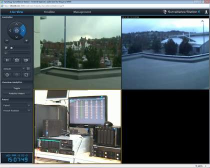
Figure 4.2.1 Visual Station
INSTRUCTION STATION-Instruction station is used to store all information of particular activity. It stores information about each and every player and also various timestamps. Each frame will pass through this station. It actually makes prediction very easy. It is used for analysing purpose. For example in defence training if there are multiple persons shooting it allows us to estimate who shot the target first.
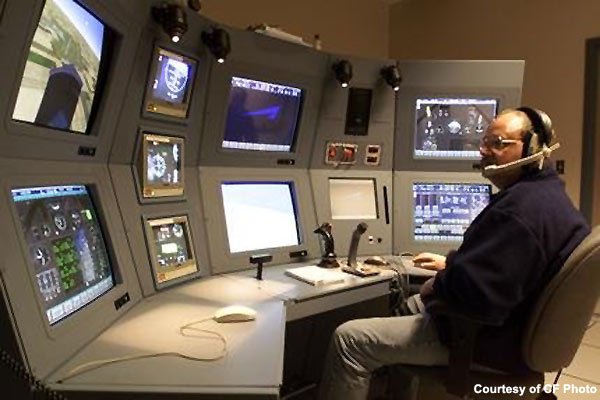
Figure 4.2.2 Instruction Station
INPUT/OUTPUT STATION-Body tracking is the motion capture method is often used to record the user’s movements and translate the captured data into inputs for the virtual simulation. For example if a person turns his head it could be directly recognized by computer hardware and automatically corresponds shift in view within the simulation. To capture human body parts movement suits and capture gloves are used. It many have i.e. the system may have different sensors to actually sense the movements of different body parts(e.g. fingers). These systems could have exterior following devices or marks which will be detected by external ultrasound, optical receivers or magnetism sensors. Internal inertial sensors are also obtainable in few systems. The units could transmit information either wirelessly or through cables. Eye trackers can even notice eye movements so the system can verify exactly wherever a user is observing any given instant
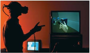
Figure 4.2.3 Input Device
There are numerous kinds of output hardware that are available to deliver to the stimulus users in virtual simulations. Visual displays offer the visual information to the user. Stationary displays will do modification from a conventional desktop pre senation to 360-degree wrap around screens to stereo three-dimensional screens. Standard desktop displays will vary in size from fifteen to 60+ inches. Wrap around screens are primarily utilized in what’s referred to as a cave automatic virtual setting (CAVE). Stereo three-dimensional screens turn out three-dimensional pictures either with or with not special glasses—depending on the planning. Head-mounted displays (HMDs) have little delineate that are mounted on headgear worn by the user. These systems are connected directly into the virtual simulation to produce the user with a lot of immersive expertise. Weight, update rates and field of read are a number of the key variables that distinguish HMDs. Naturally, heavier HMDs are undesirable as they cause fatigue over time. If the update rate is simply too long, the system is unable to update the displays quick enough to correspond with a fast head flip by the user. Slower update rates tend to cause simulation illness and disrupt the sense of immersion. Field of read or the angular extent of the universe that’s seen at a given moment field of read will modify from system to alternative system and has been recognized to have an effect on the users sense of immersion.
Aural display is an audio systems exist to assist the user hear and localize sounds spatially. Special package are often accustomed manufacture 3D audio effects 3D audio to make the illusion that sound sources are placed inside an outlined three-dimensional area round the user. Stationary customary speaker systems could also be utilised to supply dual or multi-channel surround sound. However, external speakers don’t seem to be as effective as headphones in manufacturing 3D audio effects. Typical headphones give transportable alternative to stationary speakers. They even have the additional benefits of masking universe noise and facilitate more practical 3D audio sound effects.
Haptic displays offer sense of bit to the user. This kind of output is typically noted as force feedback. Tactile tile displays use numerous styles of actuators like expansive bladders, vibrators, low frequency sub-woofers, pin actuators and/or thermo-actuators to provide sensations for the user. End effector displays will reply to user’s inputs with resistance and force. These systems area unit often times employed in medical applications for remote surgeries that use robotic instruments.
Vestibular displays offer a way of motion to the user. They typically manifest as motion bases for virtual vehicle simulation like driving simulators or flight simulators. Actuators are used to progress the simulator that can construct the sensation pitching, yawning or rolling whereas motion bases are fixed. The simulators can also move in a way to bring out a sense of acceleration on all axes, e.g., the motion base can bring out the sensation of falling.
4.3 UML DIAGRAMS
The Unified Modelling Language (UML) is a standard language for writing software blue prints. The UML is a language for
- Specifying
- Visualizing
- Constructing
- Documenting the artefacts of a software intensive system.
The UML is a language which provides vocabulary and the rules for combining words in that vocabulary for the purpose of communication. A modelling language is a language whose vocabulary and the rules focus on the conceptual and physical representation of a system. Modelling is required for the understanding of a system.
The vocabulary of the UML encompasses three kinds of building blocks:
- Things
- Relationships
- Diagrams
Things are the abstractions that are first-class citizens in a model; relationships tie these things together; diagrams group interesting collections of things.
There are four kinds of things in the UML:
- Structural things
- Behavioral things
- Grouping things
- Annotational things
Structural things are said to be the nouns of UML models. The structural things used in the project design are: Classes, Use Cases and Nodes First, a class is a description of a set of objects that share the same attributes, operations, relationships and semantics.
Window
Origin
Size
open()
close()
Figure 5.3.1.1 Classes
Second, a use case is a description of set of sequence of actions that a system performs that yields an observable result of value to particular actor.
Figure 4.3.2 Use Cases
Third, a node is a physical element that exists at runtime and represents a computational resource, generally having at least some memory and often processing capability.

Figure 4.3.3 Node
Behavioral things are the effective parts of UML models. The behavioral thing used is: Interaction: An interaction is a behaviour that comprises a set of messages exchanged among a set of objects within a particular context to accomplish a specific purpose. An interaction involves a number of other elements, including messages, action sequences (the behaviour invoked by a message, and links (the connection between objects).
Relationships in the UML
- Dependency
- Association
- Generalization
- Realization
A dependency is a semantic relationship between two things in which a change to one thing may affect the semantics of the other thing (the dependent thing). An association is a structural relationship that describes a set links, a link being a connection among objects. Aggregation is a exceptional kind of association, representing a structural relationship between a whole and its parts.Association A generalization is a specialization/ generalization relationship in which objects of the specialized element (the child) are substitutable for objects of the generalized element (the parent). One classifier specifies a contract that another classifier guarantees to carry out in a realization is a signification relationship between classifiers. Diagram is the graphical presentation of a set of elements, rendered as a connected graph of vertices (things) and arcs (relationships). A diagram may contain any combination of things and relationships. For this reason, the UML includes nine such diagrams:
(i) Class diagram: A class diagram consists of set of classes, interfaces, and collaborations and their alliances. Class diagrams that include active classes address the static process view of a system
(ii) Object diagram:
- Object diagrams constitute/depict unchanged snapshots of examples of the things found in class diagrams
- These diagrams address the unchanged design view or static process view of a system
- An object diagram shows a set of objects and their alliances.
(iii) Use case diagram:
- A use case diagram determines a set of use cases and actors and their relationships.
- Use case diagrams address the static use case view of a system.
- These diagrams are mainly important in modelling and organizing the behaviors of a system.
(iv) Interaction Diagrams: Both sequence diagrams and collaboration diagrams are kinds of interaction diagrams Interaction diagrams address the dynamic view of a system.
(v) Sequence diagram: It is an interaction diagram that highlight the time-ordering of messages.
(vi) Communication diagram: It is an interaction diagram that highlight the structural organization of the objects that send and receive messages Sequence diagrams and collaboration diagrams are isomorphic, meaning that you can take anything one and transform it into the other.
(vii) State Chart diagram:
- A state chart diagram interprets a state machine, containing of states, transitions, events, andactivities.
- State chart diagrams address the dynamic view of a system.
- It is very important in designing the actions of an interface, class, or collaboration and determines the event-ordered behavior of an object.
(viii) Activity diagram: An activity diagram is a different kind of a state chart diagram that determines the flow from activity to activity within a system. Activity diagrams address the dynamic view of a system. They are typically important in designing the function of a system and emphasize the flow of control among objects.
(ix) Component diagram:
- A component diagram shows the organizations and dependencies among a set of components.
- Component diagrams address the static implementation view of a system.
- Component typically maps to one or more classes, interfaces, or collaborations.
that are related to class diagrams.
(x) Deployment diagram:
- A deployment diagram shows the arrangements of run-time processing nodes and the components that live on them.
- Deployment diagrams address the static deployment view of an architecture.
Use Case Diagram: A use case diagram shows a set of use cases and actors and their relationships .Here there are three trainees who are given different guns with different shapes which help the admin to recognize who actually fired the target and later the scores are stored in the score board.
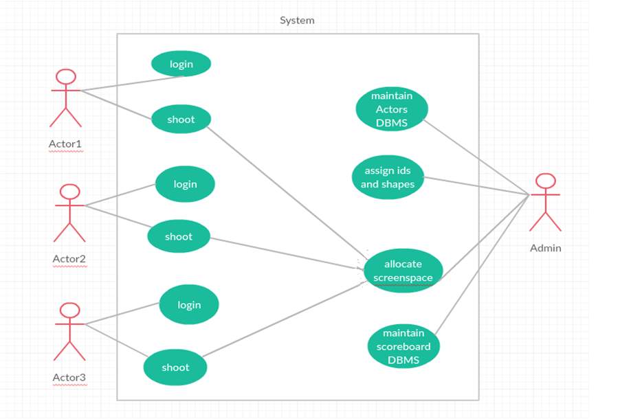
Figure 4.3.4 Use Case Diagram
The use case diagram shows action performed by different actors. The ellipse in diagram refers to action. All actions and actors are connected through association property. UML Use Case Diagrams are usually referred to as behaviour diagrams used to describe a set of actions of the trainees in the virtually created war zone and admin who is responsible of giving symbols and noting the score.
Class Diagram: A class diagram consists of set of classes, interfaces, and collaborations and their alliances. Class diagrams that include active classes address the static process view of a system. A class diagram consists of set of classes, interfaces, and collaborations and their alliances. Class diagrams that include active classes address the static process view of a system
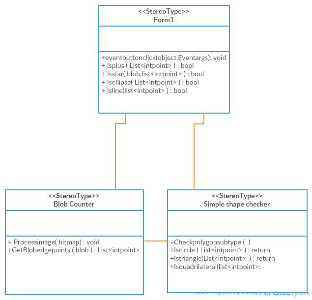
Figure 4.3.5 Class Diagram
Each rectangle box represents a class and the upper portion of it represents class name and middle portion represents attributes of the class and the lower represents the functions performed by that class.
Sequence Diagrams: is an interaction diagram that emphasizes the time-ordering of messages.
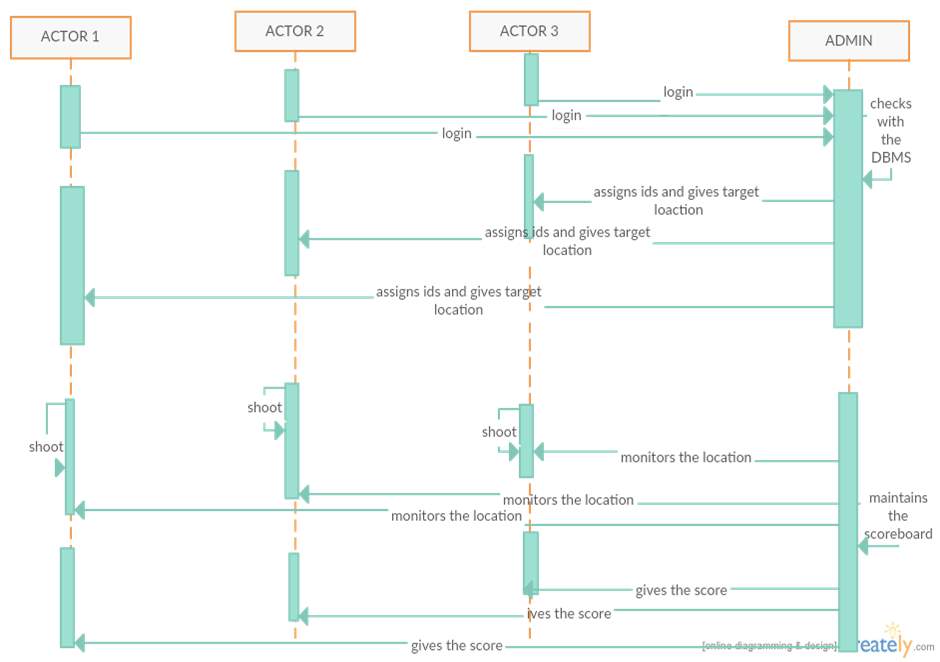
Figure 4.3.6 Sequence Diagram
The Sequence diagram shows the time ordered set of instructions that has to be performed by the user. It represents sequence or flow of messages in system among various objects of the system. The rectangle boxes at top represent objects that are invoked by user and the dashed lines dropping from those boxes are life lines which shows existence of the object up to what time. The boxes on the dashed lines are events and the lines connecting them represent messages and their flow.
Activity Diagrams: An activity diagram is a special kind of a state chart diagram that shows the flow from activity to activity within a system.
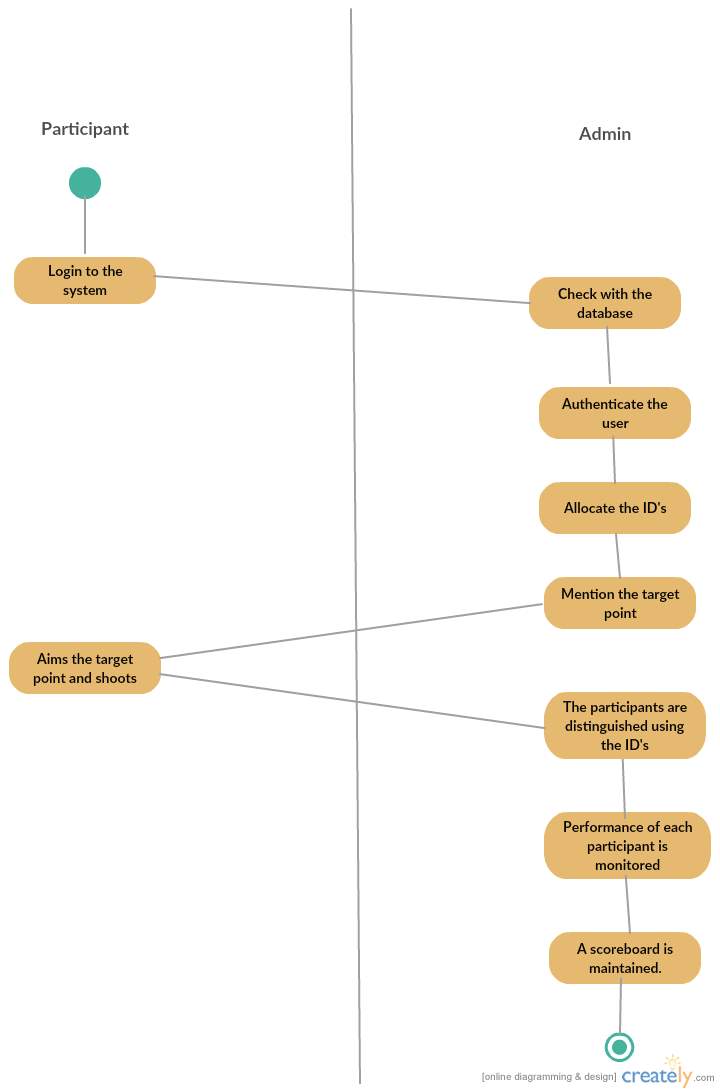
Figure 4.3.7 Activity Diagram
The Activity Diagram depicts the series of steps involved from the start of the tool to search the documents till the results are achieved along with branching. When the trainees are there stored in a database after logining admin gives them lasers to shoot the target when the multiple trainees hit the target the scores are stored by admin.
Component Diagrams: A component diagram shows the organizations and dependencies among a set of components.
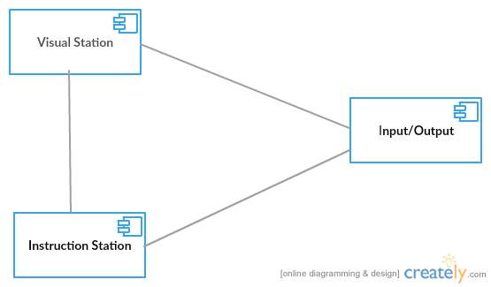
Figure 4.3.8 Component Diagram
It does not describe the functionality of the system but it describes the components used to make those functionalities.
CHAPTER 5
IMPLEMENTATION ENVIRONMENT
Implementation is the phase in which each and every person has to be alert because all the risks undertaken during the project will be very interactive. Implementation is the most crucial stage in achieving successful system and giving the users confidence that the new system is workable and effective. Each and every program is examined by individually person at the time of development using the sample data and has verified that these programs link together in the way specified in the program specification. The computer system and its environment are tested to the satisfaction of the user.
As compared to system design, the implementation phase is less creative. It is primarily concerned with user training, and file conversion. The system may be requiring extensive user training. The initial parameters of the system should be modified as a result of a programming. A simple operating procedure is provided so that the user can understand the different functions clearly and quickly. Different kinds of reports can be obtained either on the inkjet or dot matrix printer, which is available at the disposal of the user. The proposed system is very easy to implement. In general implementation is used to mean the process of converting a new or revised system design into an operational one.
5.1 C#:
C# multiprogramminglanguage,imperative,declarative,functional,generic,objectoriented(class-based), and component-oriented programming disciplines. It was emerged by Microsoft within .NET initiative and later signed as a standard by Ecma (ECMA-334) and ISO (ISO/IEC 23270:2006). C# is one of the programming languages designed for the Common Language Infrastructure. It is object-oriented programming language and c# is a general-purpose. Its development team is led by Anders Hejlsberg. The most latest emancipate version is C# 7.0 which was released in 2017 along with Visual Studio 2017.
C# programminglanguage may be a fashionable, all-purpose, object-oriented artificial language emerged by Microsoft and approved by European pc makers Association (ECMA) and International Standards Organization (ISO).C# was developed by Anders Hejlsberg and his team throughout the event of .Net Framework. C# is meant for Common Language Infrastructure (CLI),that consists of the practicable code and runtime surroundings that permits use of varied high-level languages on completely different pc platforms and architectures.
C# professional language is used word widely though following basis:
- C# is very modern and a general-purpose programming language.
- C# is object oriented.
- C# is a structured language.
- It is very easy to understand and learn.
- It is component oriented
- Many platforms can be used to compile C#
- C# is a part of .Net Framework.
Even though C# constructs relatively follow traditional high-level languages, C and C++ and being an object-oriented programming language. It has strong resemblance with Java, it has numerous strong programming features that make it endearing to a number of programmers worldwide.
Following is the list of few important features of C#:
- Automatic Garbage Collection
- Boolean Conditions
- Properties and Events
- Assembly Versioning
- Standard Library
- Delegates and Events Management
- Easy-to-use Generics
- Simple Multithreading
- Conditional Compilation
- Indexers
- LINQ and Lambda Expressions
- Integration with Window
AForge.NET – At the present moment the framework consists of 3 significant parts, which were discussed in detail in some of my previous articles:
- Image processing
- Neural network
- Evolution algorithms
Starting this project, the idea was not just in summarizing all the previous source codes from different areas and providing them to the community as they are. Excluding several libraries and their sources, the framework also makes many selected applications that indicate the usability of this particular framework, and documentation files in HTML Help format that can be used as a reference. The aim of this project is not only to extend its functionality, but to also contribute support for it, improving and enlarging its documentation and sample application set.
IMAGE PROCESSING LIBRARY
The image processing library subsists of a set of image processing filters and tools designed to address various tasks of computer vision and image analysis/processing. At the moment the library contains the below set of filters, which is growing more and more as new ones develop:
- Color filters (grayscale, sepia, invert, rotate channels, channel extraction, channel replacing, channel filtering, color filtering, Euclidean colour filtering, RGB channels linear correction)
- HSL filters (linear correction, brightness, contrast, saturation, hue modifier, HSL filtering)
- YCbCr filters (linear correction, YCbCr filtering, channel extraction/replacement)
- Binarization filters (threshold, threshold with carry, ordered dithering, Bayer dithering, Floyd-Steinberg, Burkes, Jarvis-Judice-Ninke, Sierra, Stevenson-Acre, Stuck dithering methods)
- Adaptive binarization (simple image statistics);
- Mathematical morphology filters (erosion, dilatation, opening, closing, hit & miss, thinning, thickening)
- Convolution filters (mean, blur, sharpen, edges, gaussian blur, sharpening based on gaussian kernel)
- 2 Source filters (merge, intersect, add, subtract, difference, move towards, morph)
- Edge detectors (homogeneity, difference, sobel, canny)
- Gamma correction, Median filter.
- Conservative smoothing, jitter, oil painting, pixellate, simple skeletonization.
- Blob counter and connected components labeling filter.
- Texture generators (clouds, marble, wood, labyrinth, textile), texture, textured filter, texture merge filter.
- Resize and rotation (nearest neighbor, bilinear, bicubic)
- Frequency filtering with FFT
- Image statistics
5.2 VISUAL STUDIO
From Microsoft, Microsoft Visual Studio is an integrated development environment (IDE). It is used to develop computer programs for Microsoft Windows, as well as web sites, web apps, web services and mobile apps. Microsoft software development platforms is used by various others but visual studio uses this in various platforms, such as Windows API, Windows Forms, Windows Presentation Foundation, Windows Store and Microsoft Silverlight. It can build native code and managed code.
IntelliSense and code for refactoring are included as a supporting code editor in visual studio. The integrated debugger works both as a source-level debugger and a machine-level debugger.There are different built-in tools that are included in a code profiler, forms designer for building GUI applications, class designer, web designer and database schema designer. It accepts plug-ins that enhance the functionality at almost every level—including adding support for source control systems (like Subversion) and adding new toolsets like editors and visual designers for toolsets or domain-specific languages for other aspects of the software development lifecycle (like the Team Foundation Server client: Team Explorer).
Visual Studio various built-in languages which includes C,C++ and C++/CLI .It also supports various programming languages and allows the debugger and code editor to support (to varying degrees) nearly any programming language, provided a language-specific service exists.
STL containers are especially considered in this case, where each and every container sizes have varied a lot between various compiler releases. The C++ compiler ABI have historically changed between major compiler releases. C++ interfaces at module boundaries when one wants to warrant client code compiled using a various compiler version,it is not recommended by Microsoft. Instead of C++, Microsoft recommends using C or COM interfaces, which are designed to have a stable ABI between compiler releases. There are different versions of C runtime libraries for various visual C++ ships. This means users can compile their code with any of the available libraries. However, this can cause some problems when using different components in the same program. A typical example is a program using different libraries. The user should use the same C Run-Time for all the program’s components unless the implications are understood. Microsoft recommends using the multithreaded, dynamic link library to avoid possible problems.
CHAPTER 6
CODING AND TESTING
SCANING
b2 = new Bitmap(pictureBox1.Image);
Bitmap b1 = Grayscale.CommonAlgorithms.BT709.Apply(b2);
Threshold t = new Threshold(90);
blackandwhite = t.Apply(b1);
b = UnmanagedImage.FromManagedImage(blackandwhite);
labels = new short[b.Width, b.Height];
sw = new Stopwatch();
sw.Start();
while (Convert.ToBoolean(1))
{
if (x == b.Width – 1 && y == b.Height – 1)
break;
p = b.GetPixel(x, y);
if (p.R == 0 && p.G == 0 && p.B == 0)
{
labels[x, y] = 0;
if (x < b.Width – 1)
x++;
else
{
if (y < b.Height – 1)
{
x = 0;
y++;
}
else break;
}
}
else
{
if (labels[x, y] != label && labels[x, y] == 0)
{
scan++;
if (scan == 1)
{
n.X = x;
n.Y = y;
labeller_func();
}
if (b.GetPixel(x, y).R != 0)
{
if (label != label1 && label1 != 0)
labels[x, y] = Convert.ToInt16(label1);
else
labels[x, y] = Convert.ToInt16(label);
}
f1();
}
else
{
if (x < b.Width – 1)
x++;
else
{
if (y < b.Height – 1)
{
x = 0;
y++;
}
else break;
}
}
}
}
g = sw.ElapsedMilliseconds;
Console.WriteLine(g);
sw.Stop();
public bool IsCircle(List<IntPoint> l)
{
IntPoint center;
float radius;
List<IntPoint> corners;
IntPoint minXY, maxXY, midpoint, midpoint1;
PointsCloud.GetBoundingRectangle(l, out minXY, out maxXY);
corners = PointsCloud.FindQuadrilateralCorners(l);
IntPoint cloudSize = maxXY – minXY;
center = minXY + (cloudSize / 2);
radius = ((float)cloudSize.X + cloudSize.Y) / 4;
midpoint = (minXY + center) / 2;
midpoint1.X = center.X;
midpoint1.Y = (minXY.Y + center.Y) / 2;
if (labels[midpoint.X, midpoint.Y] == 0 || labels[midpoint1.X, midpoint1.Y]==0)
{
return Convert.ToBoolean(0);
}
else
{
if (corners.Count == 4 && labels[minXY.X, minXY.Y]==0)
{
float meanDistance = 0;
for (int i = 0, n = l.Count; i < n; i++)
{
meanDistance += (float)Math.Abs(center.DistanceTo(l[i]) – radius);
}
meanDistance /= l.Count;
float maxDistance = (float)Math.Max(0.5f, (((float)cloudSize.X +
cloudSize.Y) / 2) * 0.03f);
return (meanDistance >= maxDistance);
}
else return Convert.ToBoolean(0);
}
}
public void labeller_func()
{
if (x > 0 && y > 0&&x<b.Width-1&&y<b.Height-1)
{
if (labels[x – 1, y – 1] != 0)
{
labels[x, y] = labels[x – 1, y – 1];
label1 = labels[x, y];
f1();
}
else if (labels[x, y – 1] != 0)
{
labels[x, y] = labels[x, y – 1];
label1 = labels[x, y];
f1();
}
else if (labels[x + 1, y – 1] != 0)
{
labels[x, y] = labels[x + 1, y – 1];
label1 = labels[x, y];
f1();
}
else if (labels[x – 1, y] != 0)
{
labels[x, y] = labels[x – 1, y];
label1 = labels[x, y];
f1();
}
else if (labels[x + 1, y] != 0)
{
labels[x, y] = labels[x + 1, y];
label1 = labels[x, y];
f1();
}
else if (labels[x – 1, y + 1] != 0)
{
labels[x, y] = labels[x – 1, y + 1];
label1 = labels[x, y];
f1();
}
else if (labels[x, y + 1] != 0)
{
labels[x, y] = labels[x, y + 1];
label1 = labels[x, y];
f1();
}
else if (labels[x + 1, y + 1] != 0)
{
labels[x, y] = labels[x + 1, y + 1];
label1 = labels[x, y];
f1();
}
else
{
label++;
label1 = 0;
}
}
}
public void f1()
{
if (x > 0 && y > 0&&x<b.Width-1&&y<b.Height-1)
{
if (b.GetPixel(x – 1, y – 1).R == 255 && labels[x – 1, y – 1] == 0)
{
}
else if (b.GetPixel(x, y – 1).R == 255 && labels[x, y – 1] == 0)
{
Si;
}
else if (b.GetPixel(x + 1, y – 1).R == 255 && labels[x + 1, y – 1] == 0)
{
x++;
y–;
}
else if (b.GetPixel(x – 1, y).R == 255 && labels[x – 1, y] == 0)
{
x–;
}
else if (b.GetPixel(x + 1, y).R == 255 && labels[x + 1, y] == 0)
{
x++;
}
else if (b.GetPixel(x – 1, y + 1).R == 255 && labels[x – 1, y + 1] == 0)
{
x–;
y++;
}
else if (b.GetPixel(x, y + 1).R == 255 && labels[x, y + 1] == 0)
{
y++;
}
else if (b.GetPixel(x + 1, y + 1).R == 255 && labels[x + 1, y + 1] == 0)
{
x++;
y++;
}
else
{
x = n.X;
y = n.Y;
scan = 0;
}
}
}
public bool IsLine(List<IntPoint> l)
{
IntPoint minXY, maxXY;
PointsCloud.GetBoundingRectangle(l, out minXY, out maxXY);
IntPoint cloudSize = maxXY – minXY;
List<IntPoint> corners = PointsCloud.FindQuadrilateralCorners(l);
if (cloudSize.X < 10 || cloudSize.Y < 10)
{
List<IntPoint> l1 = l.OrderBy(m => m.X).ToList();
List<IntPoint> l2 = l.OrderBy(m => m.Y).ToList();
Line line = Line.FromPoints((AForge.Point)l1[0], (AForge.Point)l1[l1.Count –
-1]);
Line line1 = Line.FromPoints((AForge.Point)l2[0], (AForge.Point)l2[l2.Count
– 1]);
float x = line.GetAngleBetweenLines(line1);
if (x >= 0 && x <= 20)
return Convert.ToBoolean(1);
else return Convert.ToBoolean(0);
}
else if (corners.Count == 4)
{
if (corners[3].Y – corners[0].Y < 10 || corners[1].X – corners[0].X < 10)
{
List<IntPoint> l1 = l.OrderBy(m => m.X).ToList();
List<IntPoint> l2 = l.OrderBy(m => m.Y).ToList();
Line line = Line.FromPoints((AForge.Point)l1[0], (AForge.Point)l1[l1.Count –
1]);
Line line1 = Line.FromPoints((AForge.Point)l2[0], (AForge.Point)l2[l2.Count –
1]);
float x = line.GetAngleBetweenLines(line1);
if (x >= 0 && x <= 20)
return Convert.ToBoolean(1);
else return Convert.ToBoolean(0);
}
else return Convert.ToBoolean(0);
}
else return Convert.ToBoolean(0);
}
public bool IsPlus(List<IntPoint> l)
{
IntPoint center;
float radius;
IntPoint minXY, maxXY, midpoint, midpoint1,midpoint2,midpoint3;
PointsCloud.GetBoundingRectangle(l, out minXY, out maxXY);
IntPoint cloudSize = maxXY – minXY;
center = minXY + (cloudSize / 2);
radius = ((float)cloudSize.X + cloudSize.Y) / 4;
midpoint = (minXY + center) / 2;
midpoint2 = (midpoint + center) / 2;
midpoint1.X = center.X;
midpoint1.Y = (minXY.Y + center.Y) / 2;
midpoint3.X = center.X;
midpoint3.Y = (midpoint1.Y + center.Y) / 2;
if (labels[midpoint.X, midpoint.Y] != 0 && labels[midpoint1.X, midpoint1.Y] != 0)
return Convert.ToBoolean(0);
else
{
List<IntPoint> l1 = l.OrderBy(m => m.X).ToList();
List<IntPoint> l2 = l.OrderBy(m => m.Y).ToList();
List<IntPoint> l3 = new List<IntPoint>();
l3.Add(l1[0]);
l3.Add(l1[l1.Count – 1]);
l3.Add(l2[0]);
l3.Add(l2[l2.Count – 1]);
l3 = l3.Distinct().ToList();
if (l3.Count == 4 || l1[0] == l2[0] || l1[l1.Count – 1] == l2[l2.Count – 1])
{
Line line = Line.FromPoints((AForge.Point)l1[0], (AForge.Point)l1[l1.Count –
1]);
Line line1 = Line.FromPoints((AForge.Point)l2[0], (AForge.Point)l2[l2.Count
1]);
float x = line.GetAngleBetweenLines(line1);
if (x >= 70 && x <= 110 || 180 – 2 * x >= 70 && 180 – 2 * x <= 110)
return Convert.ToBoolean(1);
else
return Convert.ToBoolean(0);
}
else
{
return Convert.ToBoolean(0);
}
public bool IsTriangle(List<IntPoint> l)
{
PointsCloud.QuadrilateralRelativeDistortionLimit = 0.25f;
List<IntPoint> corners = PointsCloud.FindQuadrilateralCorners(l);
corners = corners.Distinct().ToList();
if(corners.Count==3)
{
Line line = Line.FromPoints((AForge.Point)corners[0],
(AForge.Point)corners[1]);
Line line1 = Line.FromPoints((AForge.Point)corners[0],
(AForge.Point)corners[1]);
Line line2 = Line.FromPoints((AForge.Point)corners[1],
(AForge.Point)corners[1]);
floatangles=line.GetAngleBetweenLines(line1)+
+ line1.GetAngleBetweenLines(line2);
if (angles >= 140 && angles <= 180)
return Convert.ToBoolean(1);
else return Convert.ToBoolean(0);
}
else return Convert.ToBoolean(0);
}
SYSTEM TESTING
The purpose of testing is to discover errors. The process of making an attempt to get each conceivable fault or weakness in an exceedingly work product is testing. It provides some way to envision the practicality of elements, sub-assemblies, assemblies and/or a finished product it’s the method of travail software package with the intent of guaranteeing that the package meets its needs and user expectations so it doesn’t fail in an unacceptable manner. There square measure varied styles of check, every check kind addresses a particular testing demand.
6.1 TYPES OF TESTS
UNIT TESTING
Validating that the internal program logic is functioning properly Unit testing involves the design of test cases, and that valid outputs are produced from program inputs .Code flow which are decisions and internal branches should be validated .Each unit is tested through unit testing before the integration so all individual components are tested before . This is a structural testing, that depend on comprehensive of its construction and is invasive. Basic take a look ats at element level and test a selected business method, application, and/or system configuration Unit tests are performed. Unit tests make sure that every distinctive path of a business method performs accurately to the documented specifications and contains clearly outlined inputs and expected results.
INTEGRATION TESTING
Integration testing actually tests weather the software components follow the same program through out. Testing is event driven and is additional involved with the fundamental outcome of screens or fields. Integration although the elements were separately satisfaction tests demonstrate, as shown by with success unit testing, the mix of elements is correct and consistent. Integration testing is specifically aimed toward exposing the issues that arise from the mix of elements.
FUNCTIONAL TEST
As nominative by the business and technical needs that Functions tested are done by useful tests give systematic demonstrations, system documentation, and user manuals. Functionaltesting is focused on the subsequent items:
Valid Input : recognize classes of valid input must be accepted.
Invalid Input : distinguish classes of invalid input must be repudiated.
Functions : pinpoint functions must be exercised.
Output : diagnose classes of application outputs must be exercise.
Procedures : divide systems or procedures must be supplicated.
Organization and preparation of useful tests is targeted on needs, key functions, or special check cases.
SYSTEM TEST
The entire integrated software system meets requirements that System testing ensures . It tests a configuration to ensure known and predictable results. For an sample of system testing is the organisation oriented system integration test. System testing emphasizing pre-driven process links and integration points and it is also based on process descriptions and flows.
WHITE BOX TESTING
White Box Testing is a testing in which a well-known or well knowledge person performs the operation. They check for the purpose rather than specifications. Everything is visible through the white box. It can test the places where Black Box cannot reach.
BLACK BOX TESTING
The Black Box testing is a testing in which where there is no knowledge of inner environment. It does not check anything in detail. It requires only requirements and specification. It is a kind of testing a black box and cannot look anything through it. But it makes sure all the specifications are correct for the particular software or application tested.
The word Black box is kept because nothing is visible through the black box. It is quite different from white box but only difference is this testing does not check in detail.
6.2 UNIT TESTING
An element of test-driven development (TDD), a sensible methodology that takes a scrupilous approach to assembling a product by suggests that of continual testing and revision is Unit Testing. Test-driven development needs that developers initial write failing unit tests. Then code is written and refactor the appliance till the check passes. TDD generally ends up in a precise and sure code base.
Unit testing includes the attributes or variables related to the unit test all others are not included. This actually helps many developers to create a modify a source code without any difficulty. Once all of the units in a program have been found to be working in the most efficient and error-free manner, the program can be evaluated by means of integration testing, possible, larger components of.
Unit testing does have steep learning curve. The development team needs to learn about how the process of testing and how and what actually unit testing means and how use automated software tools to facilitate the process on an on-going basis. The great benefit to unit testing is that the problem is detected then there is a possibility of few errors,. Though eventually conflicts with something down the line and results in a problem.
A compound error is one that doesn’t seem to break anything at first, Though it is not uncommon for coding and unit testing to be conducted as two distinct phases.
Test objectives:
- All field entries should work properly.
- Pages should be activated from the known alliance
- The entry screen, messages and responses must not be detained.
- Features to be trailed.
- Justify that the entries are of the correct format
- No equivalent entries should be allowed
- All alliances should take the user to the correct page.
6.3 INTEGRATION TESTING
On a single platform the additional integration testing of two or more integrated software components to produce failures caused by interface defects Software integration testing. The task of the combination take a look at is to see that parts or package applications, e.g. parts during a software package or – one accelerate – package applications at the corporate level – act while not error take a look at Results: All the take a look at cases intimated on top of passed with success. No defects found.
6.4 ACCEPTANCE TESTING
For any project User Acceptance Testing may be a essential section and needs important participation by the tip user. It conjointly ensures that the system meets the practical necessities check Results: All the check cases intimated on top of passed with success. No defects found.
CHAPTER 7
RESULTS AND ANALYSIS

Figure 7.1 Main Screen
This is Designing Screen where we can perform various actions required for the application.
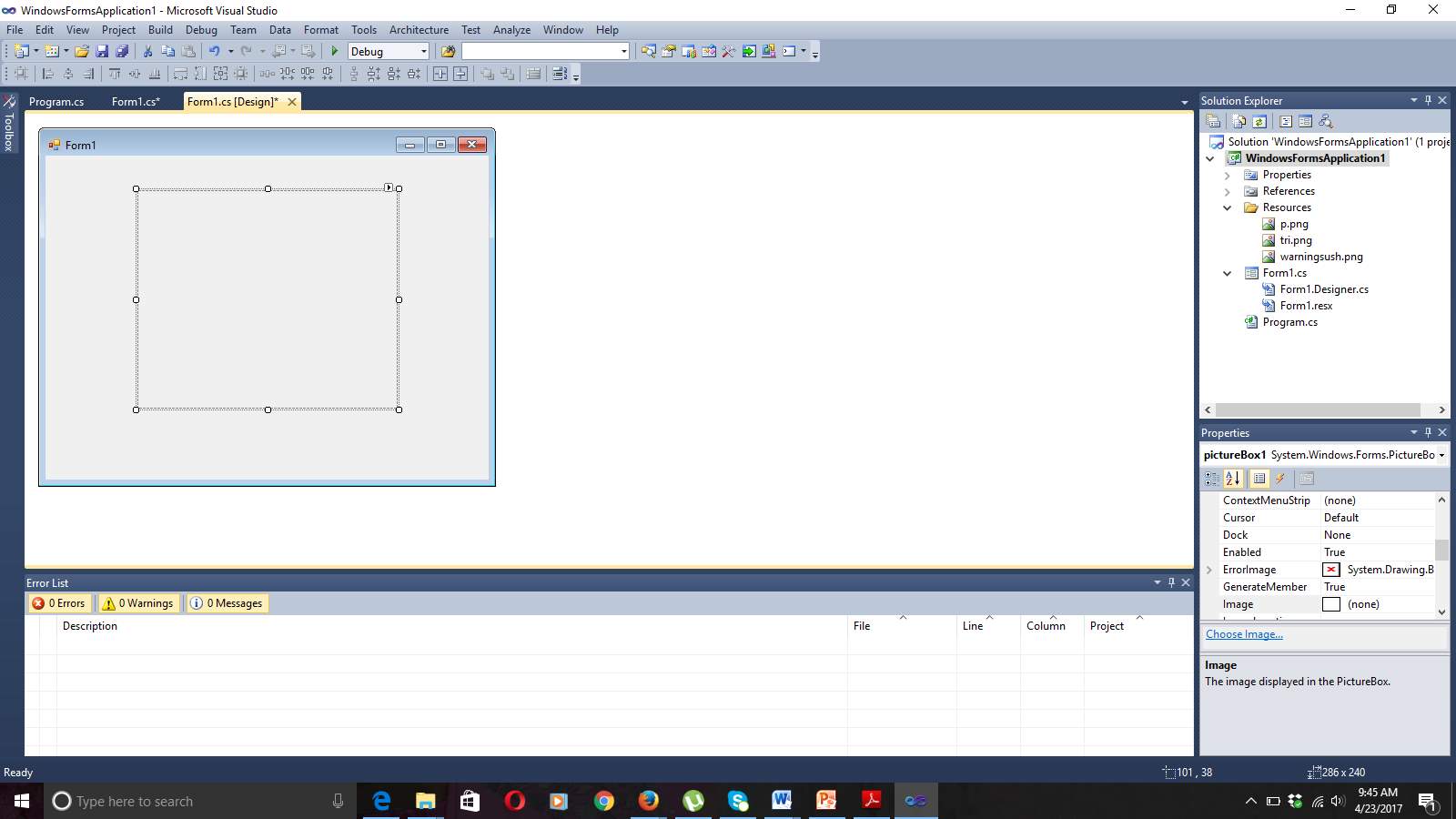
Figure 7.2 Picture Box Fetched Into Form Window
From the Tool Bar Picture Box is fetched and place in the form1 window. In Picture Box we retrieve various images.

Figure 7.3 Button Fetched Into Application
Button icon is fetched from the ToolBox. In our application button click produces various output.
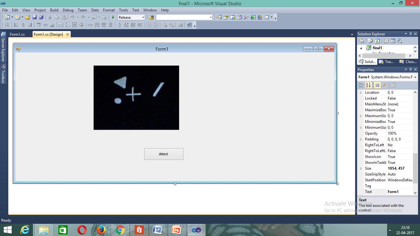
Figure 7.4Image fetched Into Form Application
Into the picture box we get an image.
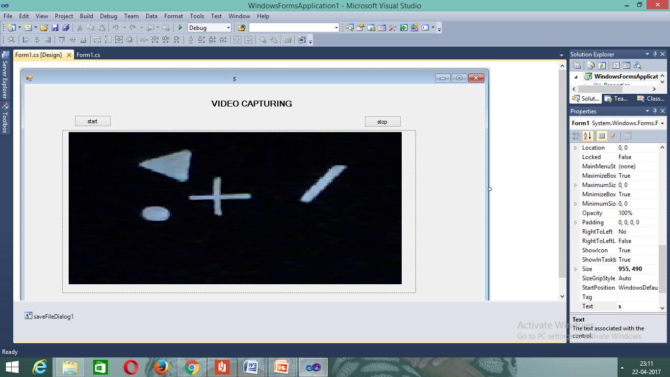
Figure 7.5 Image Capturing Through Camera
Image can be fetched into picture box. The other way is to capture through camera and place it.
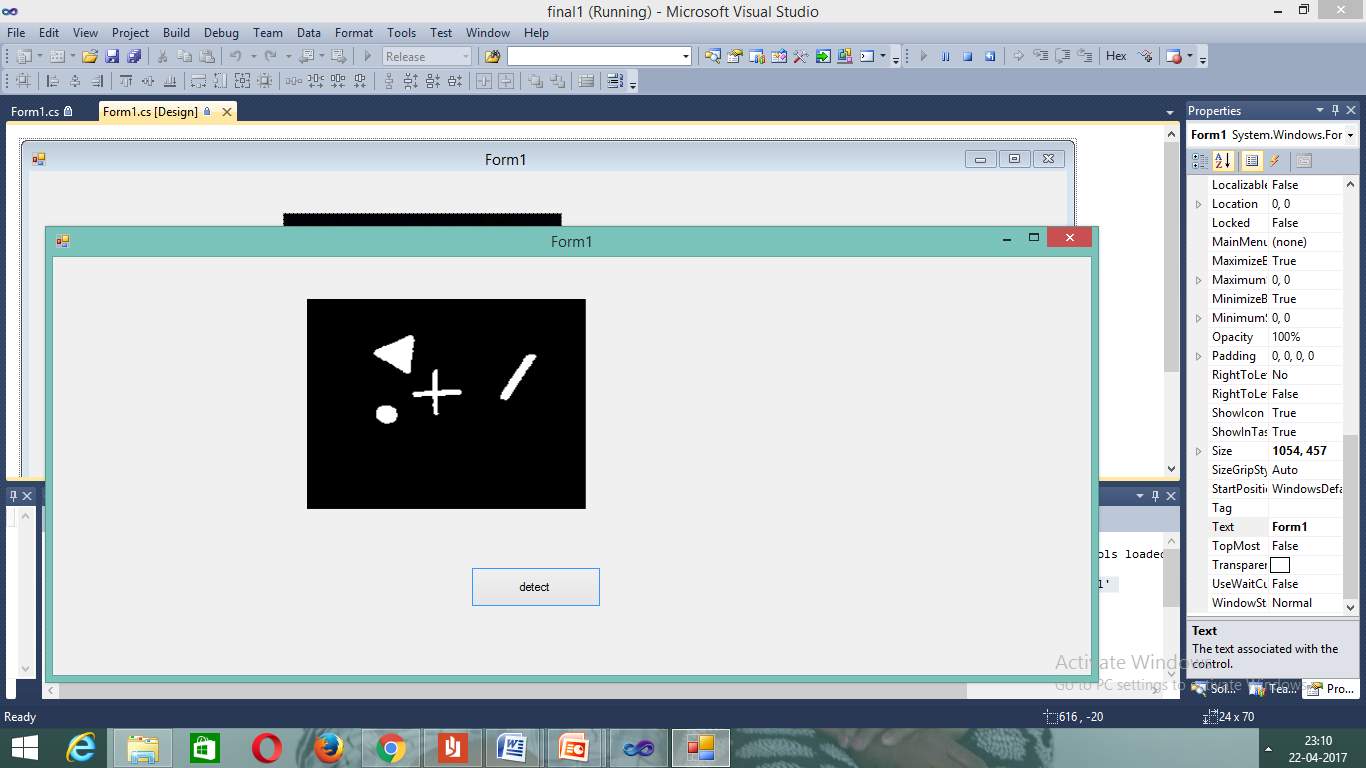
Figure 7.6 Run Application Screen
The application is running.
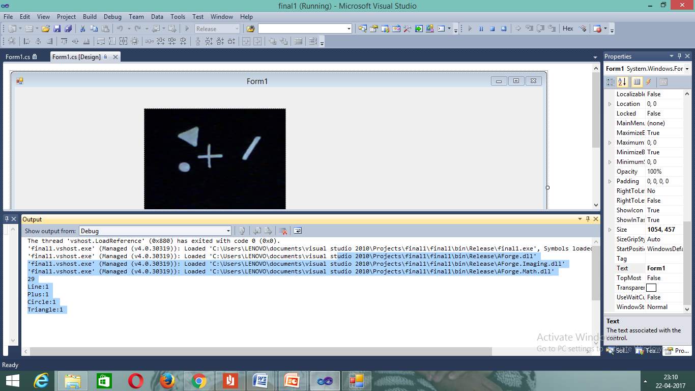
Figure 7.7 Output Screen
As we click the button it shows output in output screen. It detects objects through scanning.
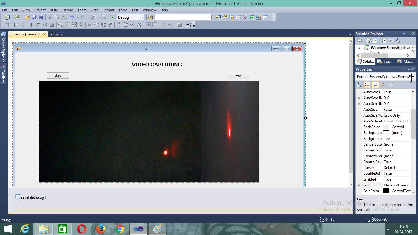
Figure 7.8 Capturing Through Laser
These are the images takes through laser.Every laser different shapes.
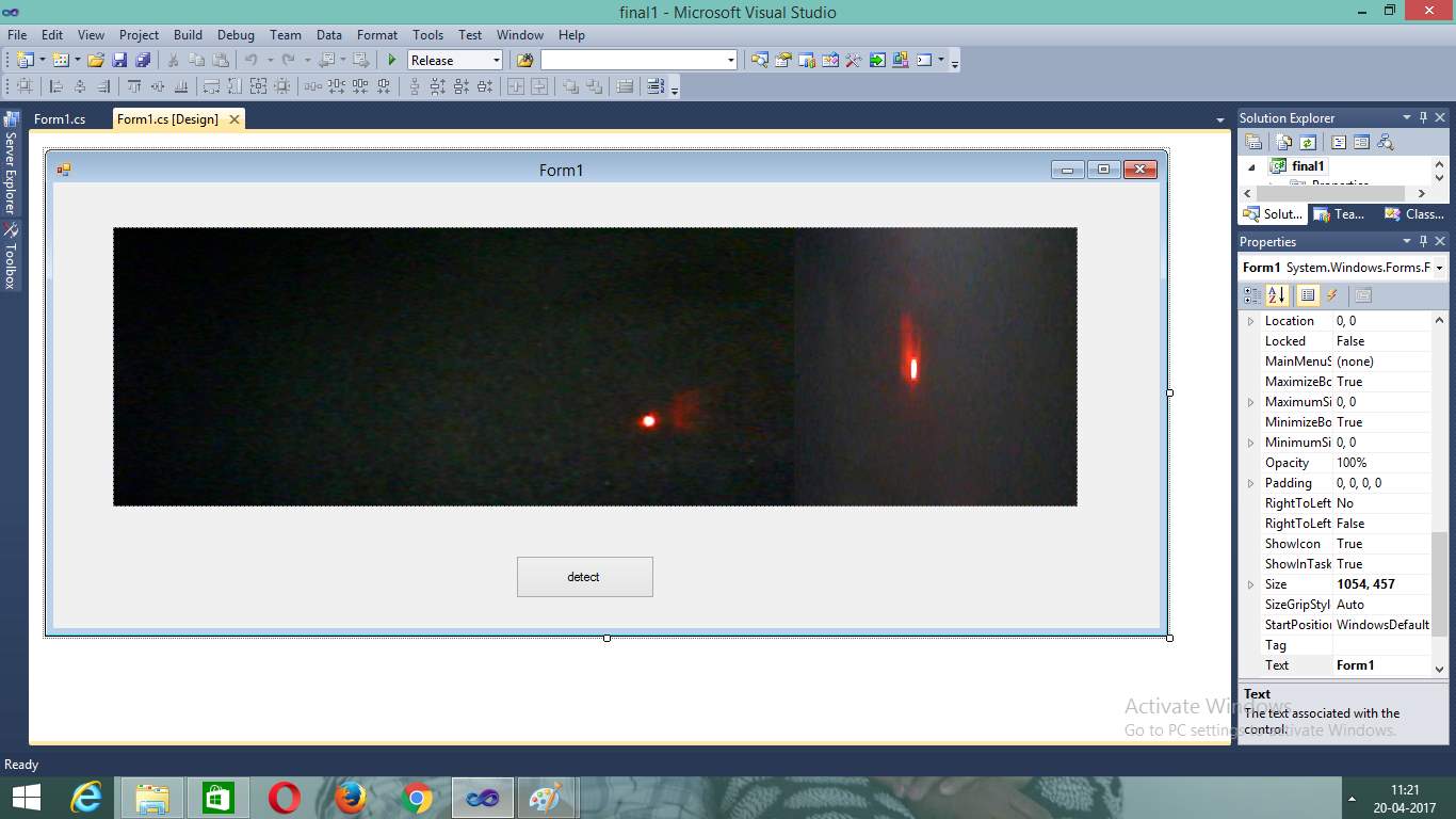
Figure 7.9 Capturing And Converting to Black And White
It converts the color image into Blackand white through grayscale.
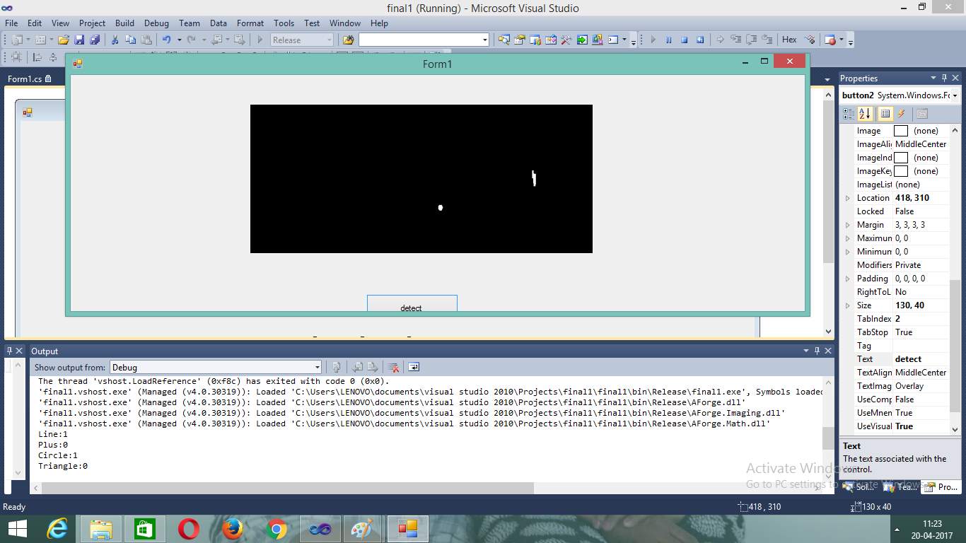
Figure 7.10 Laser Light Output
The laser points are detected and shown in the output screen
CHAPTER 8
CONCLUSION AND FUTURE SCOPE
8.1 CONCLUSION
The simulator is capable of providing comprehensive training addressing the needs of basic to expert levels. It allows the trainee to practice firing in realistic environments. Simulation is that the constraints of the operation of a real-world method or system over time. The act of simulating one thing initial needs that a model be developed; this model represents the Key characteristics, behaviours and functions of the chosen physical or abstract system or method. In virtual simulations, tactile feedback from physical controllers is very fascinating in a very range of simulation environments.
8.2 FUTURE SCOPE
It is not possible to develop a system that makes all the requirements of the user. User requirements keep changing as the system is being used. Some of the future enhancements that can be done to this system are:
- Optimising the time limit
- Multiple trainees can work on single screen
- The use of the transition station will be limited thus increases in efficiency.
Cite This Work
To export a reference to this article please select a referencing stye below:
Related Services
View all


Related Content
All TagsContent relating to: "Law Enforcement"
Law enforcement describes the organised activities, of individuals or organisations, undertaken to enforce the law. Law enforcement is typically carried out by the police force and its officers. In the UK, law enforcement is governed separately in the different legal systems of England and Wales, Northern Ireland, and Scotland.
Related Articles

DMCA / Removal Request
If you are the original writer of this dissertation and no longer wish to have your work published on the UKDiss.com website then please: